Visual Guide: Cutting Tool Grinding Defects and Solutions
Introduction
Cutting tool performance is not determined only by carbide grade or coating. In fact, grinding quality plays a critical role in tool life, cutting stability, and surface finish. During solid carbide tool manufacturing, improper grinding parameters, wheel selection, or machine setup can lead to various defects that significantly reduce tool performance.
In this article, we summarize the most common cutting tool grinding defects, analyze their root causes, and provide practical solutions based on real production experience. This guide is especially useful for manufacturers, CNC tool grinders, and quality engineers seeking to improve carbide end mill consistency and reliability.
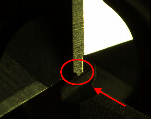
1. Bottom Edge Interference
Defect Description
Bottom edge interference occurs when parts of the bottom cutting edge overlap or collide during grinding, resulting in abnormal geometry.
Main Causes
- Excessive over-center value during bottom edge grinding
Solutions
- Optimize the grinding program
- Reduce over-center parameters
High-Risk Applications
- All types of cutting tools may encounter this issue
Engineering Warning
During machine setup, always inspect the shape of the bottom edge carefully. Small oversights can easily result in non-conforming tools.
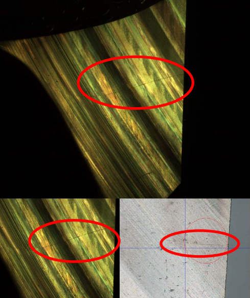
2. Cracks in Carbide Tools
Defect Description
Cracks usually appear in the flute bottom or GASH area and may not be visible at first glance.
Main Causes
- Excessive grinding depth
- Grinding feed rate too high
- Insufficient coolant supply
- Carbide material defects
Solutions
- Optimize coolant nozzle position
- Use step-by-step (layered) grinding
- Reduce grinding feed rate
High-Risk Areas
- GASH areas of chamfer tools
- Ø16 mm and above 2-flute or 3-flute tools
Engineering Warning
Cracks often start in flute bottoms or GASH areas. Careful inspection is critical to prevent defective tools from reaching customers.
3. Edge Chipping and Notches
Defect Description
Edge chipping refers to material breakage or peeling on cutting edges, including peripheral edges, corner radii, and bottom edges.

Main Causes
- Excessive grinding amount
- High grinding feed speed
- External mechanical impact
- Grinding wheel with large hard particles
- Wheel dullness
- Carbide material defects
Solutions
- Dress and sharpen grinding wheels
- Reduce grinding force and feed speed
- Protect tools from collision during handling
High-Risk Areas
- Tools with large rake angles
- Peripheral edges near flute end positions
4. Incomplete Grinding
Defect Description
Incomplete grinding appears as unremoved material on cutting edges, with shiny and reflective surfaces.

Main Causes
- Insufficient grinding feed
- Tool deflection due to low rigidity
- Insufficient grinding length
Solutions
- Increase grinding feed amount
- Improve clamping rigidity
- Extend grinding path length
High-Risk Areas
- Bottom edges with uneven bar ends
- Peripheral edges with short clamping length
- Necked tools near the tail end
5. Rough Grinding Surface
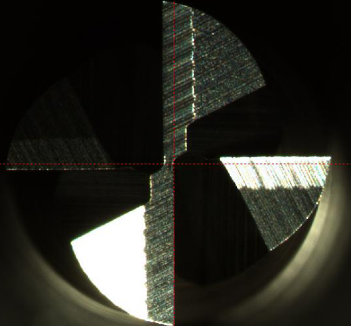
Defect Description
Grinding marks are clearly visible, resulting in poor surface finish on cutting edges.
Main Causes
- Incorrect grinding wheel selection
- Grit size too coarse
- Excessive grinding feed
- Insufficient tool rigidity
Solutions
- Use finer grit grinding wheels
- Reduce grinding feed speed
- Improve clamping rigidity
6. Serrated or Saw-Tooth Cutting Edges
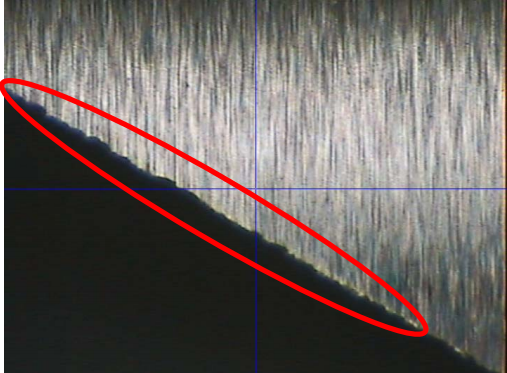
Defect Description
The cutting edge shows micro-chipping or grinding marks, forming a serrated edge profile.
Main Causes
- Coarse grinding wheel grit
- Excessive grinding feed rate
Solutions
- Select finer grit grinding wheels
- Reduce grinding feed speed
Engineering Tip
A smooth cutting edge directly affects cutting stability and tool life. Visual inspection during setup is essential.
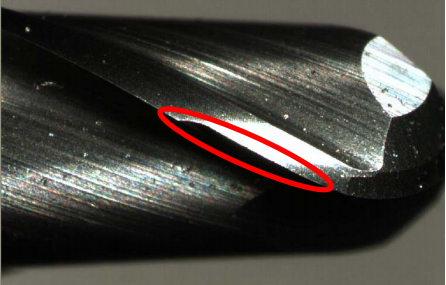
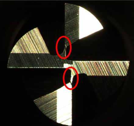
7. Incorrect Tool Geometry
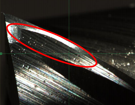

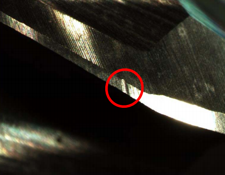
Typical Issues
- Over-cut GASH areas
- Insufficient Yp length
- Peripheral edge interference
- Excessive corner protection
- Center protrusion
- Surface pits on peripheral edges
Root Causes
- Incorrect grinding parameters
- Program errors
- Inadequate process verification
Prevention Measures
- Standardize grinding programs
- Verify geometry during first-article inspection
- Strengthen process control and documentation
Conclusion
Understanding and controlling cutting tool grinding defects is essential for producing high-quality solid carbide tools. By optimizing grinding parameters, wheel selection, coolant supply, and inspection procedures, manufacturers can significantly improve tool consistency, surface quality, and service life.
At HANYANG Tools, we apply strict grinding standards and continuous process optimization to ensure every carbide tool meets demanding machining requirements. Our experience-driven manufacturing approach helps customers achieve stable performance and lower cost per part.
Need Technical Support or Tool Optimization Advice?
Our engineering team at HANYANG Tools provides grinding and cutting parameter recommendations tailored to your materials and machines.
📩 Contact our technical team:
👉 [email protected]
👉 Contact Us
Internal Link Suggestions
- Carbide End Mill – Hanyang
- Coating Selection for Stainless & Titanium | HANYANG Tools
- Machining Tips – Hanyang