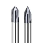
TiCN-Coated Solid Carbide Centering and Chamfer Mill 60°/90°/120°
- ◆Combines centering, spot drilling and chamfering for efficient hole-preparation operations
- ◆60°, 90° and 120° included-angle options for different chamfer, countersink and V-groove requirements
- ◆Precision-ground solid carbide geometry supports stable cutting and consistent chamfer profiles
- ◆TiCN coating improves wear resistance for steel, alloy steel, stainless steel and cast-iron machining
- ◆Custom diameters, angles, tip geometry, shank sizes and overall lengths available
Matériel de candidature :
Steel, alloy steel, stainless steel and cast iron.
Selection Note:
Spot drilling and direct plunging require a center-cutting tip configuration. Please provide the required 60°, 90° or 120° included angle, cutting diameter, flute length, shank diameter, overall length, workpiece material and order quantity for quotation.
Une qualité constante
Une géométrie constante d'une commande à l'autre.
Commandes flexibles
Petits lots et formats variés disponibles.
Assistance OEM
Marquage, étiquettes et emballages personnalisés.
Modèles standard et sur mesure
Dimensions standard et configurations sur mesure.
TiCN-Coated Centering and Chamfer Mill Overview
This TiCN-coated solid carbide centering and chamfer mill is designed for accurate hole positioning, spot drilling, edge chamfering, countersinking and V-groove preparation in ferrous materials. Available with 60°, 90° and 120° included-angle configurations, the tool allows the cutting profile to be matched to different hole-preparation and edge-finishing requirements. Precision-ground cutting geometry supports stable engagement and consistent chamfer formation, while the solid carbide substrate provides rigidity for CNC machining. TiCN coating improves wear resistance and helps reduce friction when machining steel, alloy steel, stainless steel and cast iron.
60° / 90° / 120°
Precision Ground
TiCN
Ø3–Ø20 mm
Centering & Chamfering Configuration
Three Included-Angle Options
60°, 90° and 120° configurations allow the cutting profile to be matched to different spotting, chamfering, countersinking and V-groove requirements.
Precision-Ground Cutting Geometry
Precisely ground cutting surfaces support controlled engagement, accurate centering and consistent chamfer profiles across different hole-preparation and edge-finishing operations.
TiCN Wear-Resistant Surface
TiCN coating improves wear resistance and helps reduce friction during repeated machining of steel, stainless steel, alloy steel and cast iron.
Avantages spécifiques à l'application
Flexible Angle Selection
Multiple included-angle options cover different chamfer, spotting, countersink and V-groove geometries.
Controlled Cutting Engagement
Precision-ground geometry supports stable contact and controlled cutting during centering, chamfering and angled-profile machining.
Improved Wear Resistance
TiCN coating supports repeated cutting in ferrous materials where abrasive and adhesive wear can affect tool performance.
Custom Geometry Options
Diameter, included angle, tip profile, shank size and overall length can be reviewed for application-specific and replacement-tool orders.
Opérations d'usinage recommandées
This cutter is intended mainly for centering, spot drilling, hole-edge preparation and angled-profile machining. Direct plunging or spot drilling requires a center-cutting tip geometry, which should be confirmed before ordering.
Centering
RECOMMANDÉ
Edge Chamfering
RECOMMANDÉ
Countersinking
RECOMMANDÉ
V-Groove Milling
CONVENABLE
Application Note:
Spot drilling and direct plunging require a center-cutting model. Confirm the tip geometry, required included angle and final chamfer or countersink diameter before ordering.
Compatibilité avec les matériaux des pièces à usiner
| GROUPE DE MATÉRIAUX | CONFIGURATION | APPLICATION LEVEL |
|---|---|---|
| P Steel & Alloy Steel | TiCN-coated carbide configuration for centering, chamfering and countersinking | Primary application |
| M Stainless Steel | TiCN-coated configuration with application-specific cutting conditions | Recommended |
| K Cast Iron | Wear-resistant TiCN-coated carbide configuration | Recommended |
| N Aluminum & Non-Ferrous | Use a separate uncoated, DLC-coated or material-specific low-adhesion configuration | Separate configuration |
Material Note:
The TiCN-coated version is intended mainly for ferrous-material applications. For aluminum and other non-ferrous metals, select a sharper uncoated, DLC-coated or material-specific configuration rather than automatically using the TiCN version.
Product Details & Machining Demonstration
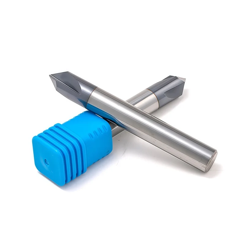
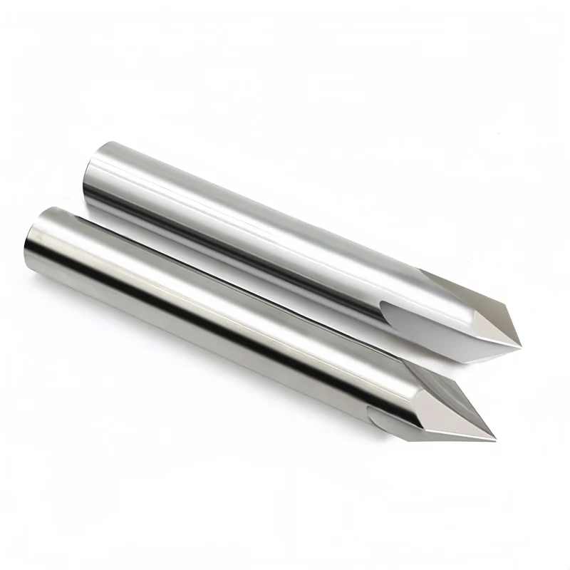
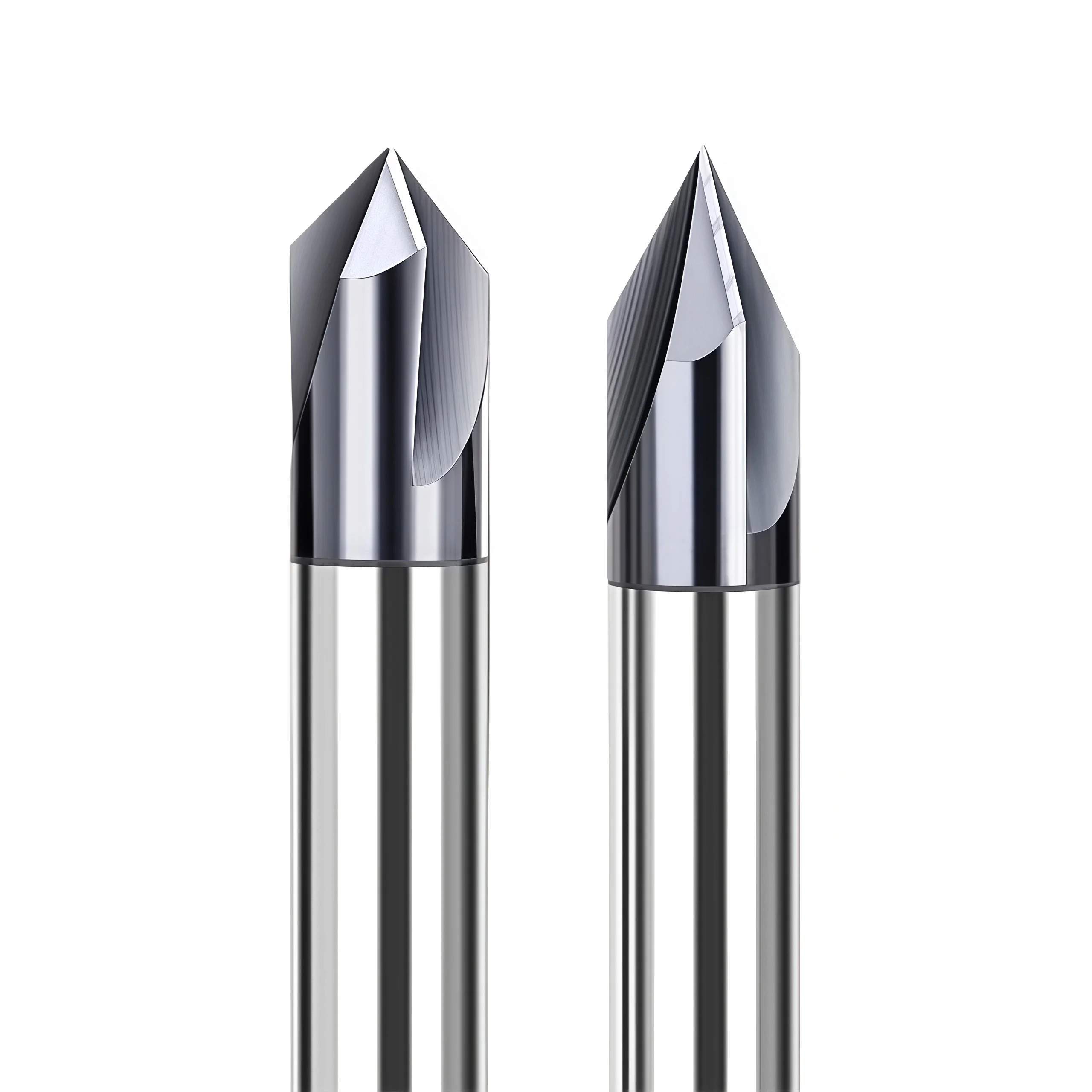
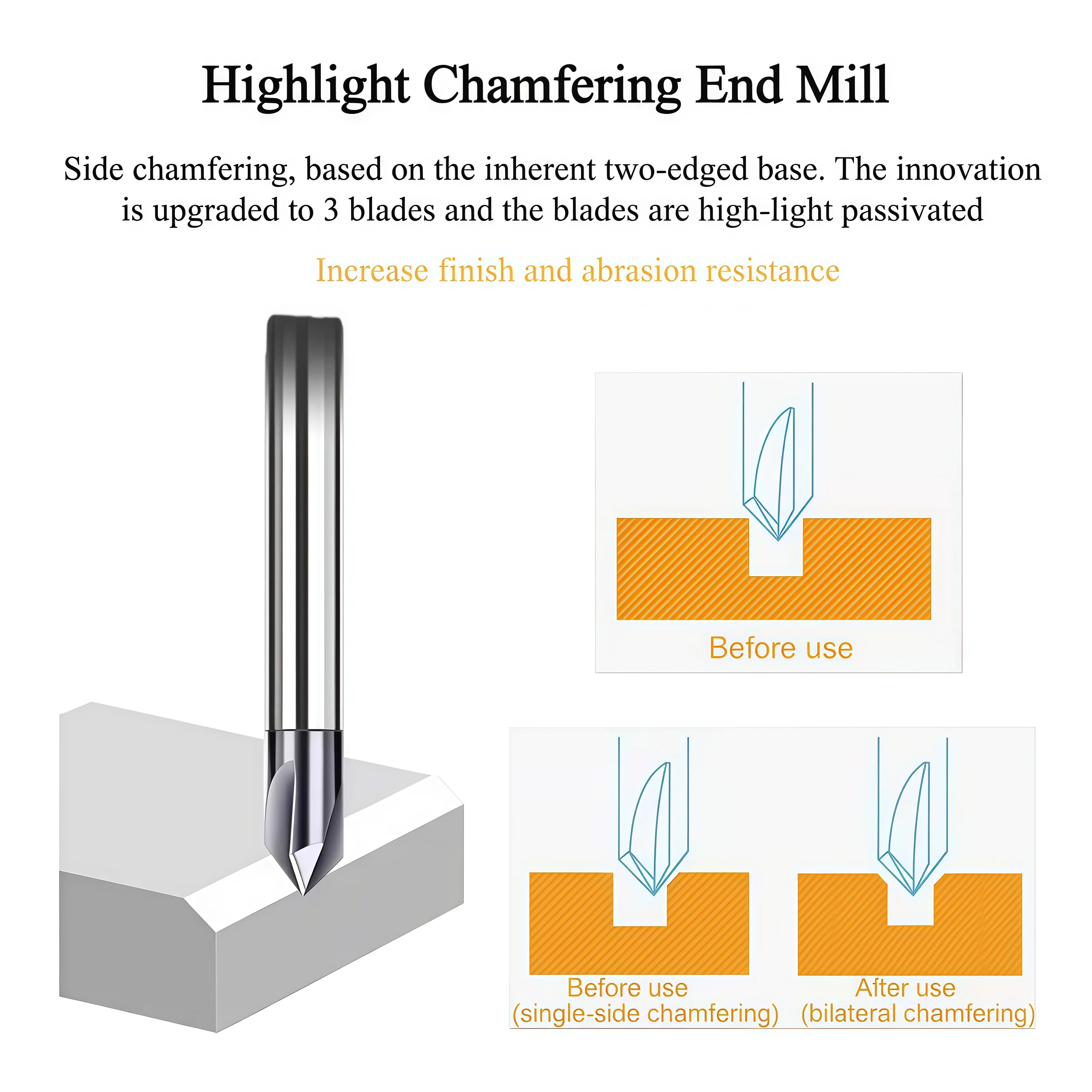
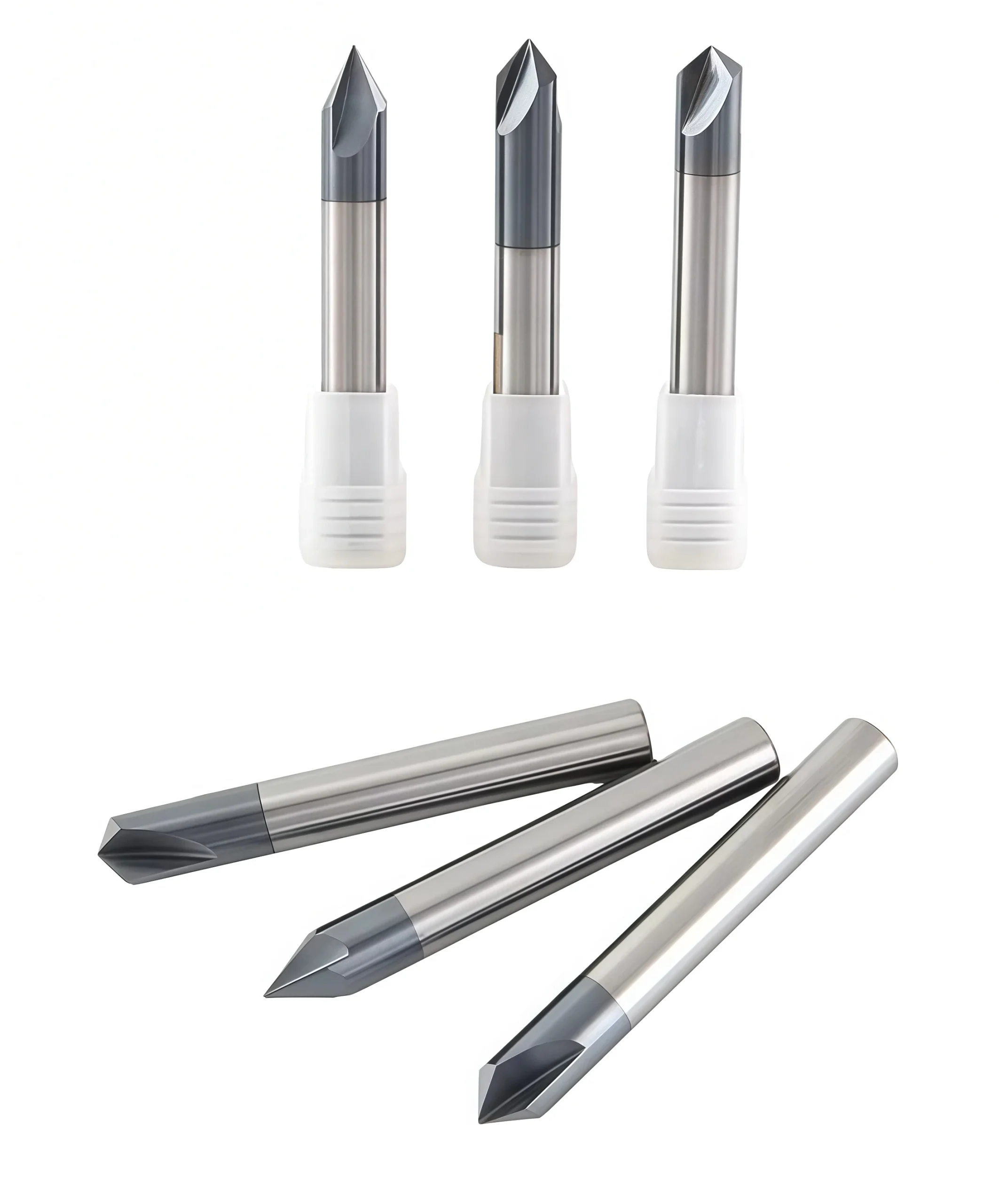
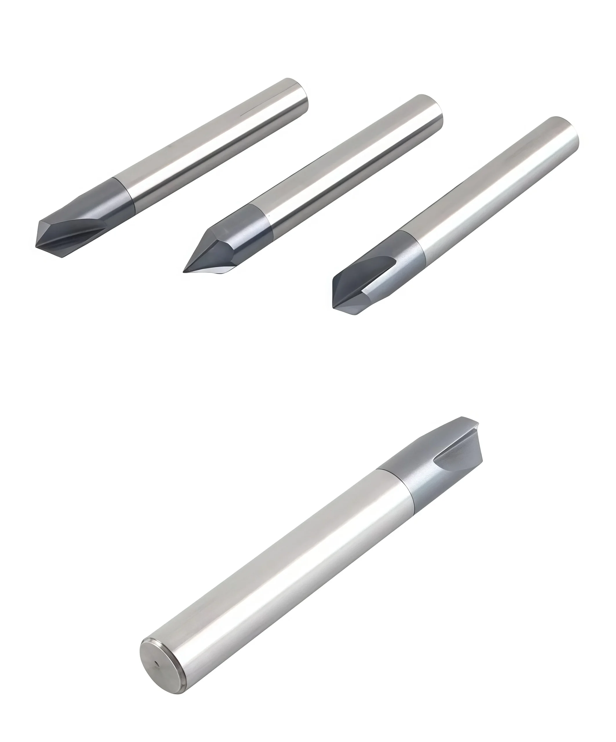
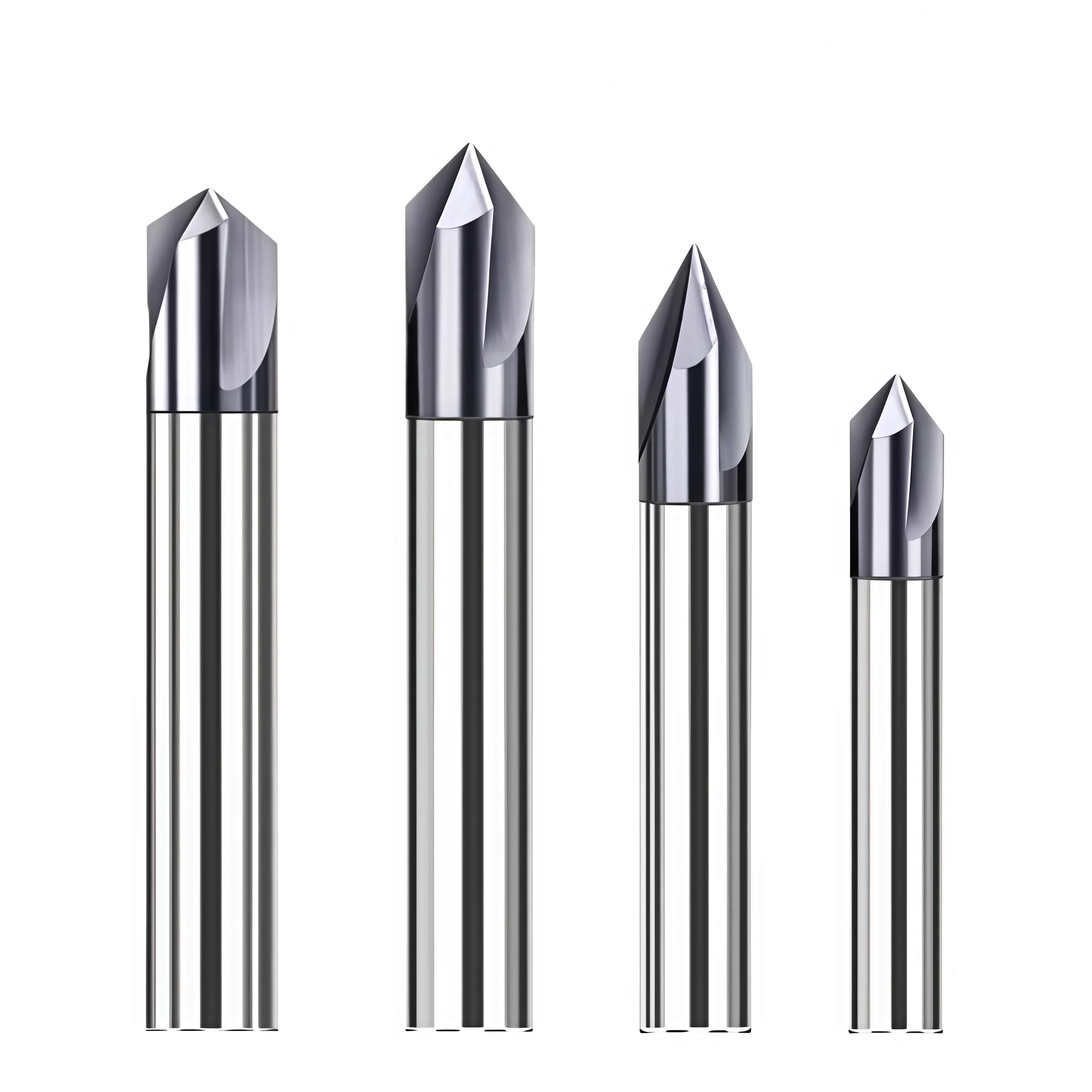
Product views of the solid carbide centering and chamfer mill, including available 60°, 90° and 120° angle configurations, cutting profiles and tool details.
Tool Nomenclature & Dimensions
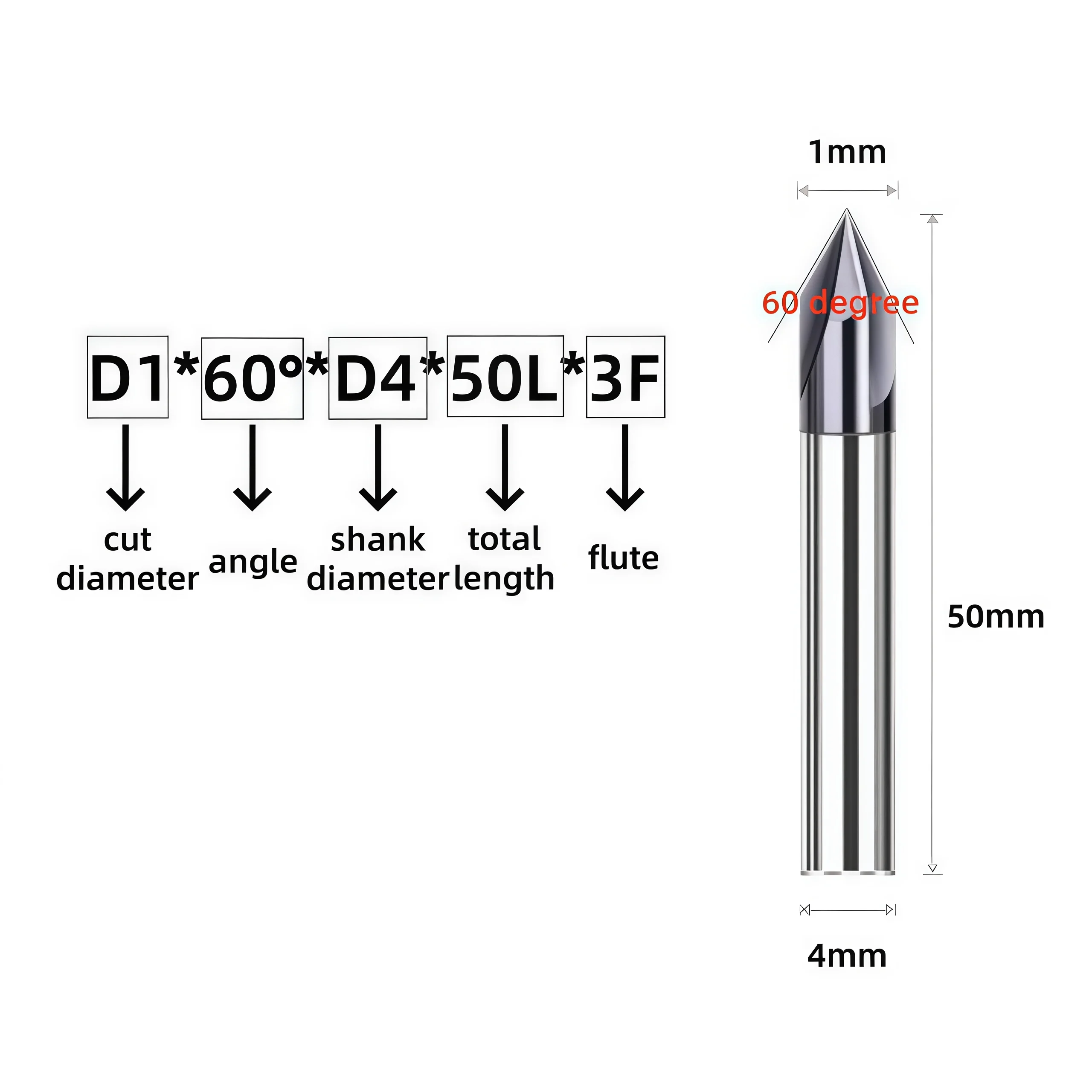
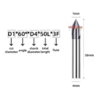
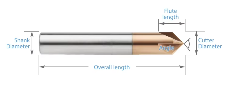
Reference dimensional nomenclature and standard configurations for the TiCN-coated solid carbide centering and chamfer mill. Available 60°, 90° and 120° included-angle configurations cover different spotting, chamfering, countersinking and V-groove requirements. Confirm the cutting diameter, included angle, flute length, shank diameter, overall length and tip geometry for the selected application. All listed dimensions are in millimeters.
Configuration technique
| PARAMÈTRE | CONFIGURATION DE RÉFÉRENCE |
|---|---|
| Matériau de l'outil | Solid Carbide |
| Type d'outil | Centering & Chamfer Mill |
| Cutting Geometry | Precision-Ground Centering & Chamfer Profile |
| Included Angles | 60° / 90° / 120° |
| Cutting Diameter Range | Ø3–Ø20 mm |
| Flute Length Range | 8–40 mm according to cutting diameter |
| Shank Diameter Range | Ø3–Ø20 mm |
| Longueur totale | 50 / 60 / 75 / 100 mm reference configurations |
| Revêtement | TiCN |
| Primary Workpiece Materials | Steel / Alloy Steel / Stainless Steel / Cast Iron |
| Opérations principales | Centering / Spot Drilling / Chamfering / Countersinking / V-Groove Milling |
| Center-Cutting Requirement | Center-cutting tip geometry must be confirmed for direct plunging and spot-drilling applications. |
| Custom Configuration | Cutting diameter, included angle, flute length, shank diameter, overall length, tip geometry and coating can be reviewed according to drawing and application requirements. |
Standard Size Matrix
Reference dimensional series for 60°, 90° and 120° solid carbide centering and chamfer mills. Confirm the required included angle and center-cutting tip configuration according to the actual machining operation.
| CUTTING DIA. D | ANGLE A | FLUTE LENGTH L1 | SHANK DIA. d | OVERALL LENGTH L |
|---|---|---|---|---|
| 3 | 60° / 90° / 120° | 8 | 3 | 50 |
| 4 | 60° / 90° / 120° | 10 | 4 | 50 |
| 5 | 60° / 90° / 120° | 12 | 5 | 50 |
| 6 | 60° / 90° / 120° | 15 | 6 | 50 |
| 7 | 60° / 90° / 120° | 16 | 7 | 60 |
| 8 | 60° / 90° / 120° | 17 | 8 | 60 |
| 9 | 60° / 90° / 120° | 19 | 9 | 75 |
| 10 | 60° / 90° / 120° | 20 | 10 | 75 |
| 11 | 60° / 90° / 120° | 23 | 11 | 75 |
| 12 | 60° / 90° / 120° | 25 | 12 | 75 |
| 14 | 60° / 90° / 120° | 30 | 14 | 100 |
| 16 | 60° / 90° / 120° | 35 | 16 | 100 |
| 18 | 60° / 90° / 120° | 38 | 18 | 100 |
| 20 | 60° / 90° / 120° | 40 | 20 | 100 |
Centering & Chamfering Application Guidance
- Angle Selection: Match the 60°, 90° or 120° included angle to the following drill geometry, countersink specification, chamfer profile or V-groove requirement.
- Center Cutting: Confirm the tip geometry before using the tool for direct plunging or spot drilling. Not every chamfer configuration should automatically be treated as center cutting.
- Chamfer Depth: Control axial depth carefully because the finished chamfer or countersink diameter changes with tool penetration.
- Toolholding: Use a clean, low-runout precision holder to maintain accurate centering, stable cutting and consistent chamfer dimensions.
- Tool Overhang: Use the shortest practical overhang to maintain rigidity, particularly with larger diameters and deeper feature access.
- Material Selection: Use the TiCN-coated configuration mainly for steel, alloy steel, stainless steel and cast iron. For aluminum and other non-ferrous materials, review an uncoated, DLC-coated or material-specific low-adhesion configuration separately.
TiCN-Coated Chamfer Mill Customization
Cutting diameter, included angle, flute length, shank diameter, overall length, tip geometry, cutting-edge preparation and coating can be configured for centering, spot drilling, chamfering, countersinking and V-groove machining. Reference configurations cover Ø3–Ø20 mm cutting diameters with 60°, 90° and 120° included-angle options. Non-standard dimensions and application-specific cutting geometry can be reviewed according to the workpiece material, required chamfer or hole profile, machining depth, tool reach, holder configuration and dimensional requirements.
| PARAMÈTRE | CAPACITÉS DE FABRICATION |
|---|---|
| Cutting Diameter | Reference cutting diameters range from Ø3 to Ø20 mm. Intermediate and non-standard diameters can be reviewed according to the required chamfer, countersink, groove or hole-preparation geometry. |
| Angle inclus | 60°, 90° and 120° included-angle configurations are available for different centering, spotting, chamfering, countersinking and V-groove requirements. Non-standard angles can be reviewed from drawings where required. |
| Cutting Geometry | Precision-ground cutting geometry can be matched to the required angle, workpiece material, cutting engagement and finished edge profile. Final flute and edge configuration are confirmed according to the selected model and application. |
| Center-Cutting Tip | Center-cutting tip geometry can be reviewed for applications requiring spot drilling or direct axial entry. Please specify whether the tool will be used for centering, plunging or chamfering only. |
| Chamfer & Countersink Profile | Included angle, target chamfer diameter and cutting profile can be matched to the component drawing, countersink specification or required edge-break geometry. |
| V-Groove Geometry | 60°, 90° and 120° profiles can also be reviewed for V-groove machining where the required groove angle and cutting depth are compatible with the tool geometry. |
| Longueur de la cannelure | Reference flute lengths range from 8 to 40 mm according to cutting diameter. Non-standard flute lengths can be reviewed where additional reach or a specific feature depth is required. |
| Configuration de la tige | Reference shank diameters range from Ø3 to Ø20 mm. Standard or drawing-defined shank sizes and clamping lengths can be reviewed according to holder compatibility and machine setup. |
| Longueur totale | Reference overall lengths include 50, 60, 75 and 100 mm. Custom overall length can be reviewed where additional reach, fixture clearance or holder access is required. |
| Une préparation à la pointe de la technologie | Rake geometry, relief, edge preparation and flute finishing can be reviewed according to the workpiece material, chamfer width, cutting load and required edge quality. |
| TiCN Coating | TiCN coating can be selected for ferrous-material applications where improved wear resistance and reduced friction are required during repeated centering, chamfering and countersinking operations. |
| Workpiece Material | The TiCN-coated configuration is intended mainly for steel, alloy steel, stainless steel and cast iron. For aluminum and other non-ferrous materials, uncoated, DLC-coated or other material-specific configurations can be reviewed separately. |
| Application d'usinage | Geometry can be reviewed for centering, spot drilling, edge chamfering, countersinking, hole-edge preparation and V-groove machining on CNC machining centers and milling machines. |
| Dimensional Requirements | Drawing-defined requirements can be reviewed for cutting diameter, included angle, flute length, shank diameter, overall length, tip geometry, chamfer profile and tool runout. |
Services OEM et de marque de distributeur
Des options de fabrication OEM et d'approvisionnement sous marque de distributeur sont proposées aux distributeurs industriels, aux marques d'outillage et aux clients ayant des commandes récurrentes. Le marquage laser, le contenu des étiquettes, l'emballage de protection et la finition du revêtement peuvent être personnalisés conformément au cahier des charges approuvé et aux exigences de la commande.

Gravure au laser
Les logos personnalisés, les codes d'outils, les dimensions de coupe, l'identification du revêtement et les numéros de lot peuvent être marqués en fonction de la surface disponible sur la tige.
Étiquettes et emballages personnalisés
Il est possible de consulter les tubes de protection individuels, les étiquettes des produits, les détails techniques, les tubes d'emballage colorés et les emballages sous marque de distributeur.
Conditions commerciales
La quantité minimale de commande (MOQ), l'évaluation des échantillons, les essais de dimensions personnalisées, les commandes répétées et les programmes d'approvisionnement planifiés sont confirmés en fonction de la configuration choisie.
Processus technique
Un processus de contrôle structuré est mis en œuvre afin de vérifier la conformité des fraises à bout carré standard, sur mesure et de marque propre avant leur mise en production.
Demande de renseignements
Veuillez indiquer le matériau, la dureté, l'opération de fraisage, les dimensions, les tolérances et la quantité.
Ingénierie
Vérifier la géométrie de la canule, l'angle d'hélice, la préparation des bords, le revêtement, ainsi que les paramètres ap et ae.
Commercial
Confirmez le devis, la quantité minimale de commande (MOQ), les exigences relatives aux échantillons, le calendrier de production et les conditions de livraison.
Production
Rectification CNC, usinage des faces d'extrémité, préparation des arêtes, revêtement et marquage laser.
Contrôle qualité
Vérifiez le diamètre, la longueur de la rainure, la tige, le faux-rond, la géométrie de l'extrémité carrée et les arêtes de coupe.
Qualité, contrôle et livraison
Nos fraises à bout carré en carbure monobloc font l'objet d'un contrôle comprenant la vérification des matériaux, la rectification de précision, des mesures en cours de fabrication et un contrôle final. Les dimensions clés, la géométrie du bout carré, l'état des arêtes de coupe, l'aspect du revêtement et l'identification du produit sont vérifiés conformément au cahier des charges ou au plan approuvé avant l'emballage.

Contrôle qualité en trois étapes
Des points de contrôle sont mis en place tout au long du processus de fabrication afin de garantir la cohérence dimensionnelle et de faciliter le suivi des commandes récurrentes.
Contrôle des entrées de marchandises
La qualité du substrat en carbure, les dimensions des ébauches et les informations relatives au matériau fourni sont vérifiées par rapport aux exigences de production.
Contrôle du broyage en cours de fabrication
Le diamètre de coupe, la géométrie des goujures, la longueur des goujures, le profil de l'extrémité carrée et les dimensions de la tige sont contrôlés pendant le meulage CNC.
Inspection finale des outils
Les outils finis font l'objet d'un contrôle portant sur les cotes spécifiées, le faux-rond, l'état des arêtes de coupe, l'aspect du revêtement, le marquage et l'identification sur l'emballage.
Caractéristiques clés d'inspection
Les exigences en matière d'inspection sont définies conformément au cahier des charges standard du produit ou au plan personnalisé approuvé.
| POINT D'INSPECTION | POINT FORT : LE CONTRÔLE | BASE DE CONFIRMATION |
|---|---|---|
| Diamètre de coupe (DC) | Diamètre et homogénéité dimensionnelle | Cahier des charges standard ou plan homologué |
| Longueur de la flûte (APMX) | Longueur de coupe effective | Dimensions du produit confirmées ou exigences relatives au dessin |
| Diamètre de la tige (DCON) | Dimensions de la section de serrage et état de surface | Spécifications applicables à la tige |
| Longueur totale (OAL) | Longueur totale de l'outil | Matrice aux dimensions standard ou plan homologué |
| Faux-rond radial | Concentricité entre la partie coupante et la tige | Exigence d'inspection convenue |
| Géométrie à extrémité carrée | Profil de la face d'extrémité, état des angles et forme de la coupe centrale | Configuration de l'outil sélectionnée |
| Profil cannelé et hélicoïdal | Nombre de cannelures, forme de l'hélice et régularité de l'affûtage | Configuration de fabrication approuvée |
| Techniques de découpe et de revêtement | État des bords, défauts visibles et aspect du revêtement | Exigences de production spécifiques à l'application |
| Marquage et identification | Code de l'outil, dimensions et informations sur le lot, le cas échéant | Confirmation de la commande et spécifications d'emballage |
Mesure et traçabilité des lots
Les systèmes de mesure optique, les équipements de contrôle des outils et les jauges dimensionnelles adaptées sont choisis en fonction de la caractéristique à contrôler.
Mesure optique
Vérification du profil et des cotes des éléments de découpe spécifiés.
Vérification du faux-rond
Contrôle de la concentricité sur la base des exigences convenues pour le produit.
Inspection des bords
Examen approfondi de l'état de la face d'extrémité, des angles et du tranchant.
Identification des lots
Les informations relatives à la commande, au produit et au lot sont associées lorsque cela est nécessaire pour assurer la continuité de l'approvisionnement.
Procédé d'emballage de protection
Les fraises finies sont protégées afin de limiter le contact entre les arêtes de coupe et de garantir une identification claire des produits pendant le stockage et le transport.

Emballage pour commandes en gros et exportation
Les expéditions en vrac peuvent être organisées à l'aide de cartons renforcés, d'emballages de protection, d'un chargement sur palettes ou de caisses d'exportation, en fonction de la quantité commandée, du poids de l'envoi et des exigences de transport convenues.

Coordination des livraisons
La finalisation de la production, le mode d'emballage et les modalités d'expédition sont confirmés conformément à la commande validée. Les options d'expédition (par coursier, par avion, par voie maritime ou selon les instructions du client) peuvent être examinées en fonction du volume de l'envoi et de sa destination. Le délai de livraison définitif est confirmé une fois que les spécifications du produit, la quantité et les exigences d'emballage ont été validées.
FAQ sur les produits et leurs applications
Answers to common questions about selecting and applying the TiCN-Coated Solid Carbide Centering and Chamfer Mill in 60°, 90° and 120° configurations for centering, spot drilling, chamfering, countersinking and V-groove machining.
What operations is this centering and chamfer mill designed for?
How should I choose between 60°, 90° and 120°?
Can this tool be used for spot drilling?
What is the advantage of the precision-ground cutting geometry?
What is the benefit of TiCN coating?
Is the TiCN-coated version recommended for aluminum?
FAQ sur les commandes et la personnalisation
Information for distributors, tooling suppliers and industrial customers requesting standard or customized solid carbide centering and chamfer mill configurations.
What standard sizes are available?
Can non-standard angles or dimensions be customized?
Can the tip geometry be customized for center cutting?
Proposez-vous le marquage OEM et le conditionnement sous marque de distributeur ?
Quel est le délai de livraison habituel ?
What information is required for an accurate quotation?
Téléchargements techniques
Use the following references for solid carbide cutter selection and starting machining-data review.
Catalogue de fraises en carbure monobloc
Review related chamfer mills, centering tools, square-end, ball-nose and application-specific solid carbide cutter series.
Guide des vitesses et des avances des fraises en bout
Access reference starting parameters for application review and controlled machining trials.
Vous avez besoin d'informations sur les tailles, les prix ou les options personnalisées ?
Veuillez nous indiquer le type d'outil requis, ses dimensions, les quantités, le matériau de la pièce à usiner ainsi que toute exigence spécifique à un équipementier ou toute demande sur mesure. Nous vous confirmerons les caractéristiques techniques adaptées, la disponibilité, le délai de livraison et les détails du devis.
Les croquis, les listes de dimensions et les photos de référence sont les bienvenus.