MFL Series Left Hand Solid Carbide Micro Face Grooving Bars for Small Bore Machining
Tutarlı Kalite
Tekrarlanan siparişlerde tutarlı geometri.
Esnek Siparişler
Küçük partiler ve farklı boyutlarda seçenekler mevcuttur.
OEM Desteği
Özel işaretleme, etiketler ve ambalajlama.
Standart ve Özel
Standart boyutlar ve özel konfigürasyonlar.
MFL Left-Hand Micro Face Grooving Bar Overview
The MFL series is a precision-ground solid carbide micro face grooving bar designed for left-hand machining of face grooves in small bores and restricted internal features. Its compact cutting geometry provides controlled access to confined machining areas, while the integral carbide construction supports rigidity, dimensional consistency and stable cutting performance in precision CNC turning applications.
Model Identification Guide
Identify the suitable MFL model according to tool series, left-hand cutting direction, shank diameter, groove width, working length and overall tool length.
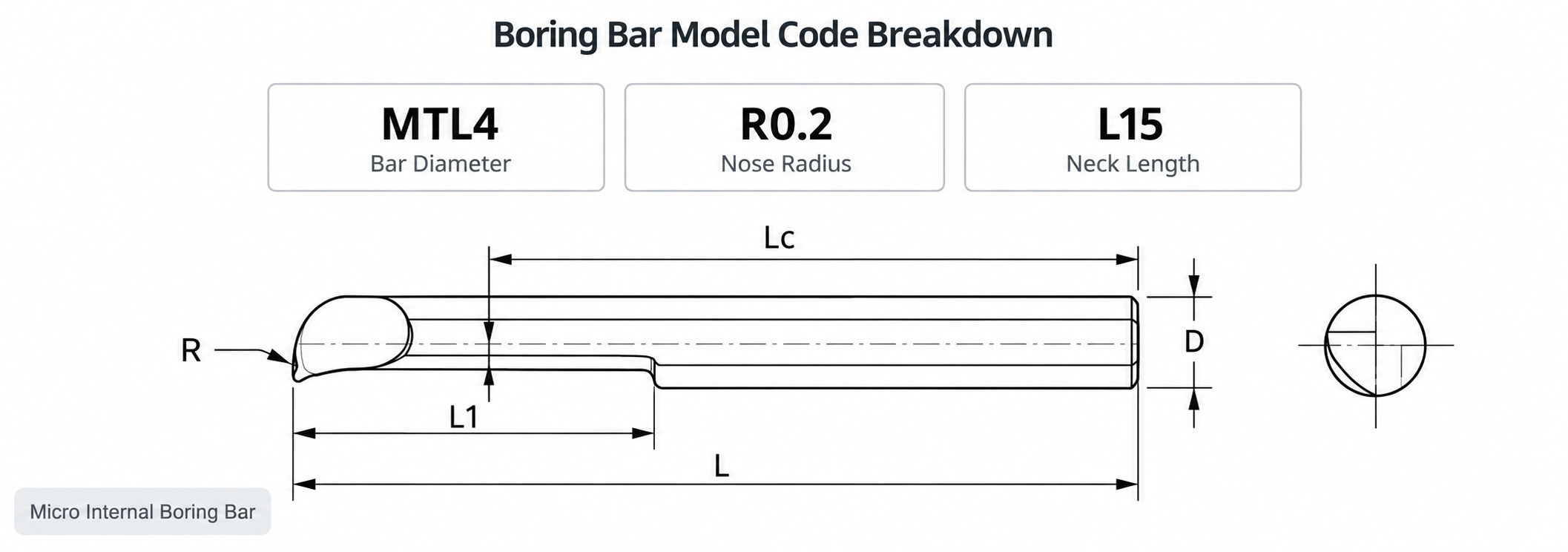 MFL model structure for selecting groove width, shank diameter and working length
Key Configuration
Machinable Materials
MFL solid carbide micro face grooving bars can be applied to precision components made from steel, stainless steel, cast iron and selected non-ferrous materials. Final cutting parameters should be adjusted according to material hardness, groove dimensions and machine stability.
| Malzeme | Tipik Uygulamalar |
|---|---|
| Karbon Çelik | Precision mechanical parts, shafts, sleeves and small turned components. |
| Alaşımlı Çelik | Wear-resistant components requiring stable groove dimensions and surface quality. |
| Paslanmaz Çelik | Medical, electronic and corrosion-resistant precision components. |
| Dökme Demir | Small housings, sleeves and precision face-groove features. |
| Non-Ferrous Materials | Aluminum, copper and other materials with application-matched edge preparation. |

Key Product Advantages
Dedicated left-hand geometry supports reverse tool approach and machining setups where conventional right-hand tools cannot obtain suitable access.
Compact cutting geometry provides controlled access to narrow face grooves and restricted internal features in miniature components.
The integral solid carbide body improves rigidity and helps reduce cutting vibration during precision face-grooving operations.
Precision-ground geometry supports consistent groove width, controlled cutting action and repeatable dimensional performance.
Groove width, groove depth, minimum machining diameter, working length, shank size, coating and marking can be customized according to drawings.
Why Choose MFL Micro Face Grooving Bars
| Özellik | Conventional Tools | MFL Solution |
|---|---|---|
| Tool Access | Standard orientation may not suit reverse or confined machining positions. | Left-hand geometry supports application-specific tool approach. |
| Sertlik | Long or less rigid tooling may increase vibration in small bores. | Solid carbide construction improves stability and vibration control. |
| Groove Consistency | Cutting instability may affect groove width and surface finish. | Precision-ground edges support consistent groove dimensions. |
Product Details
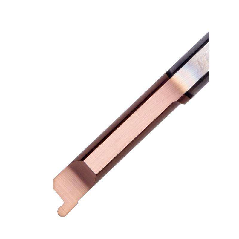
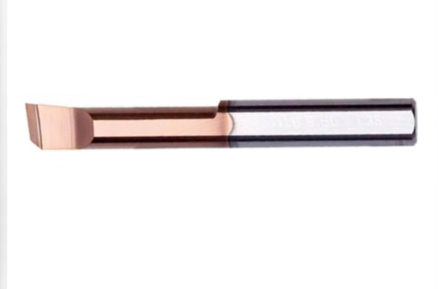
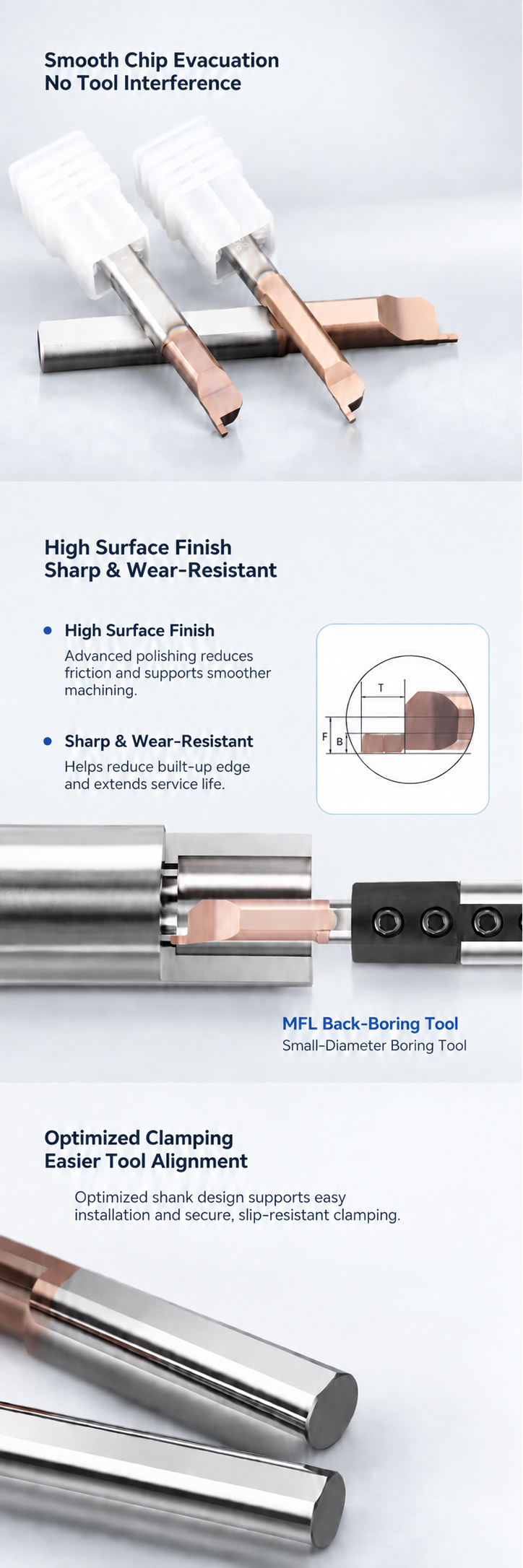
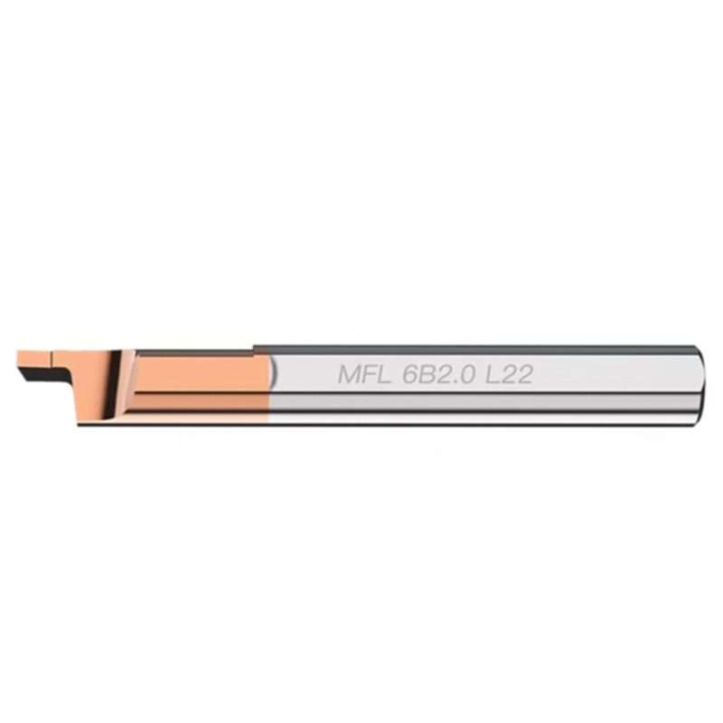
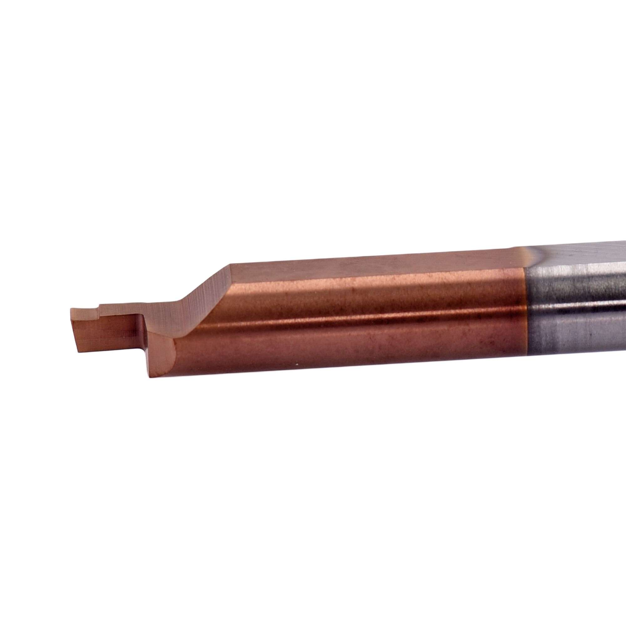
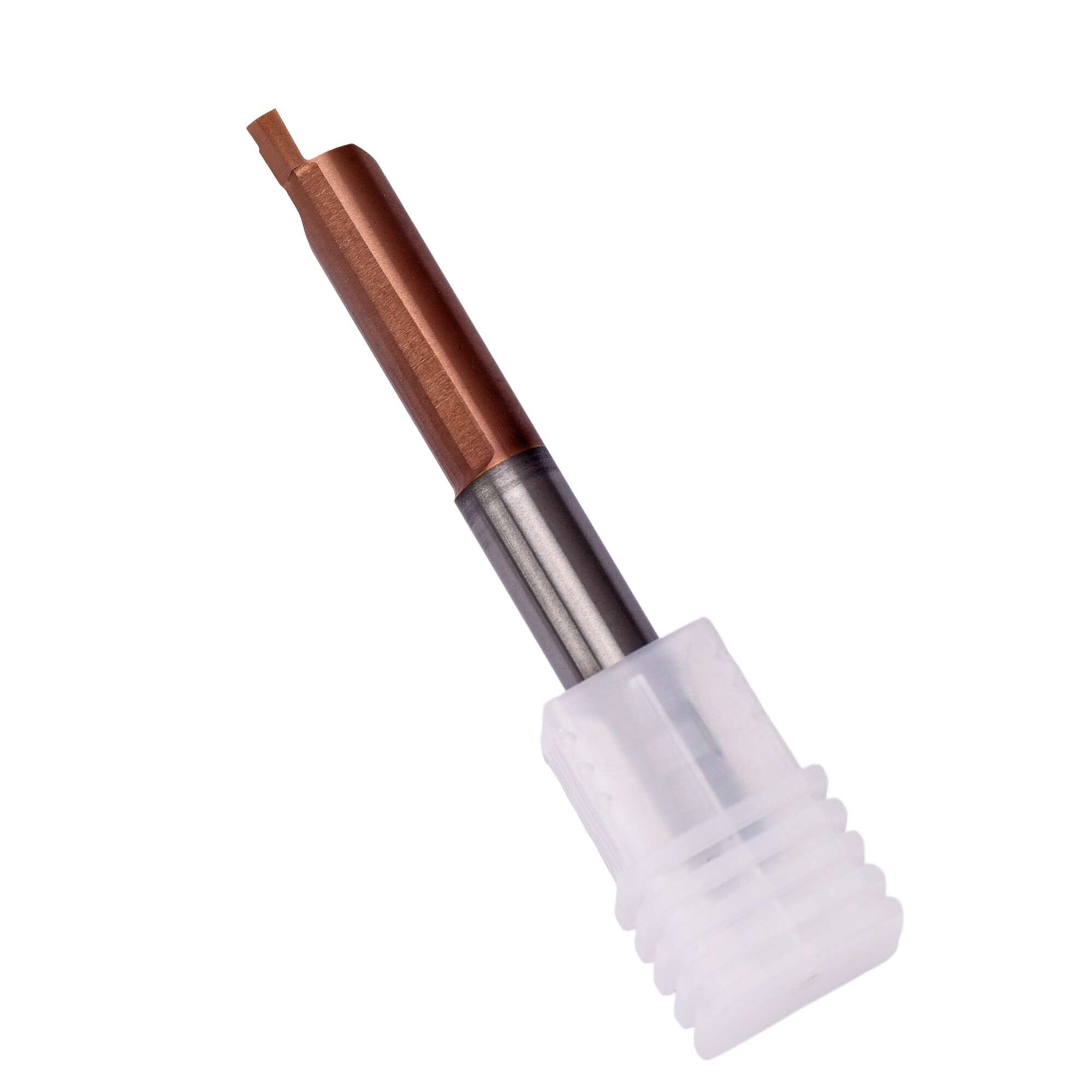
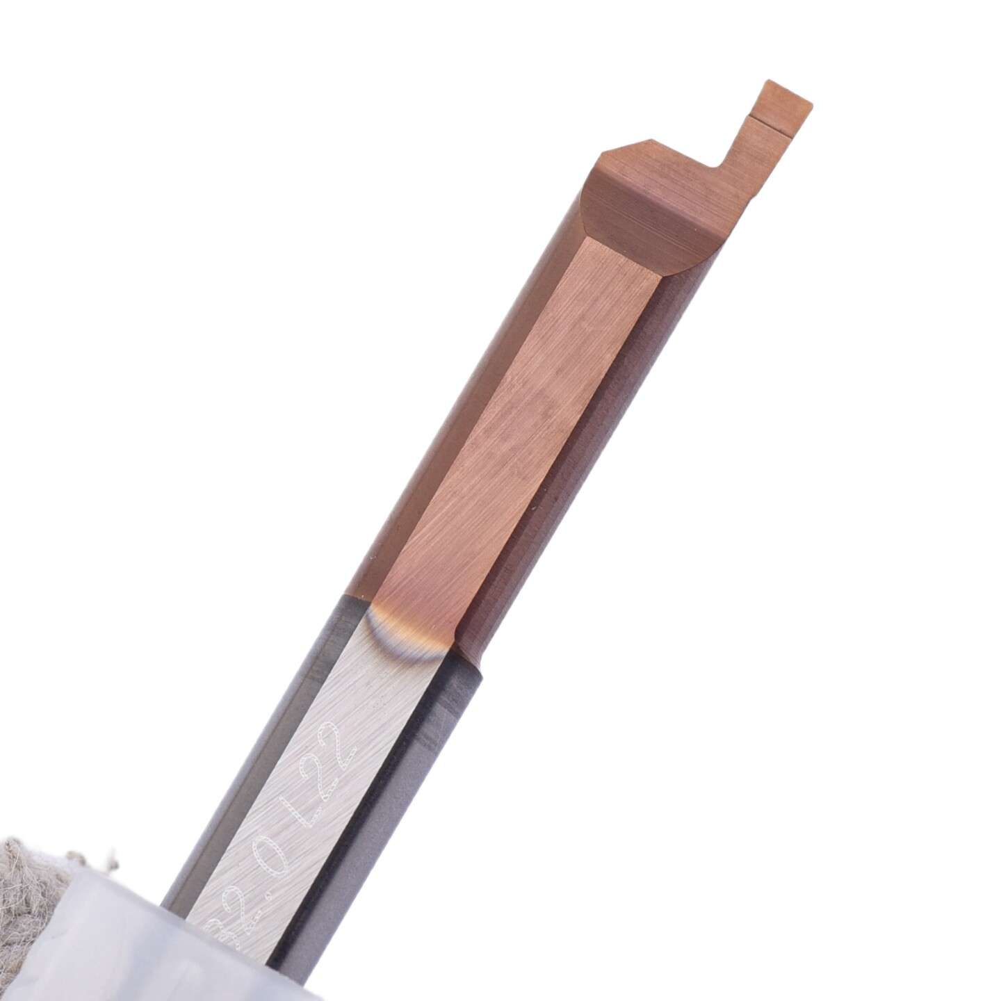
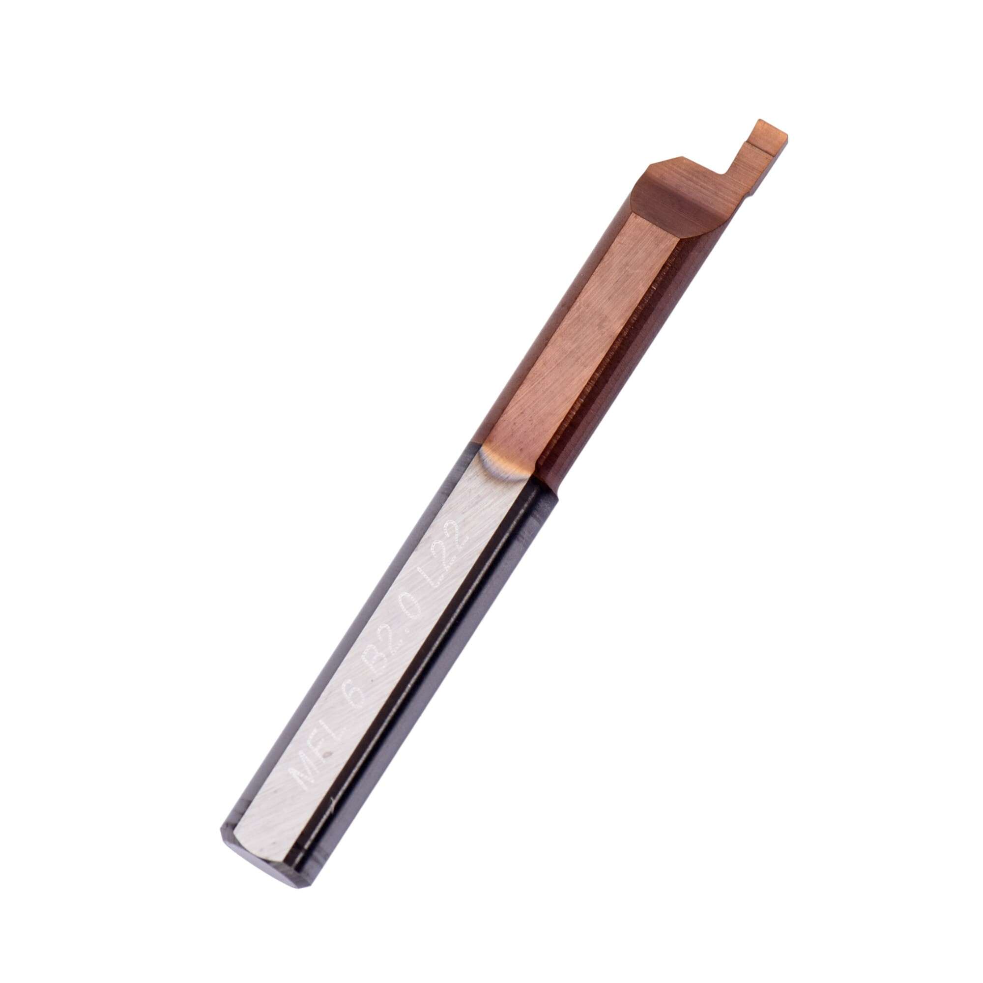
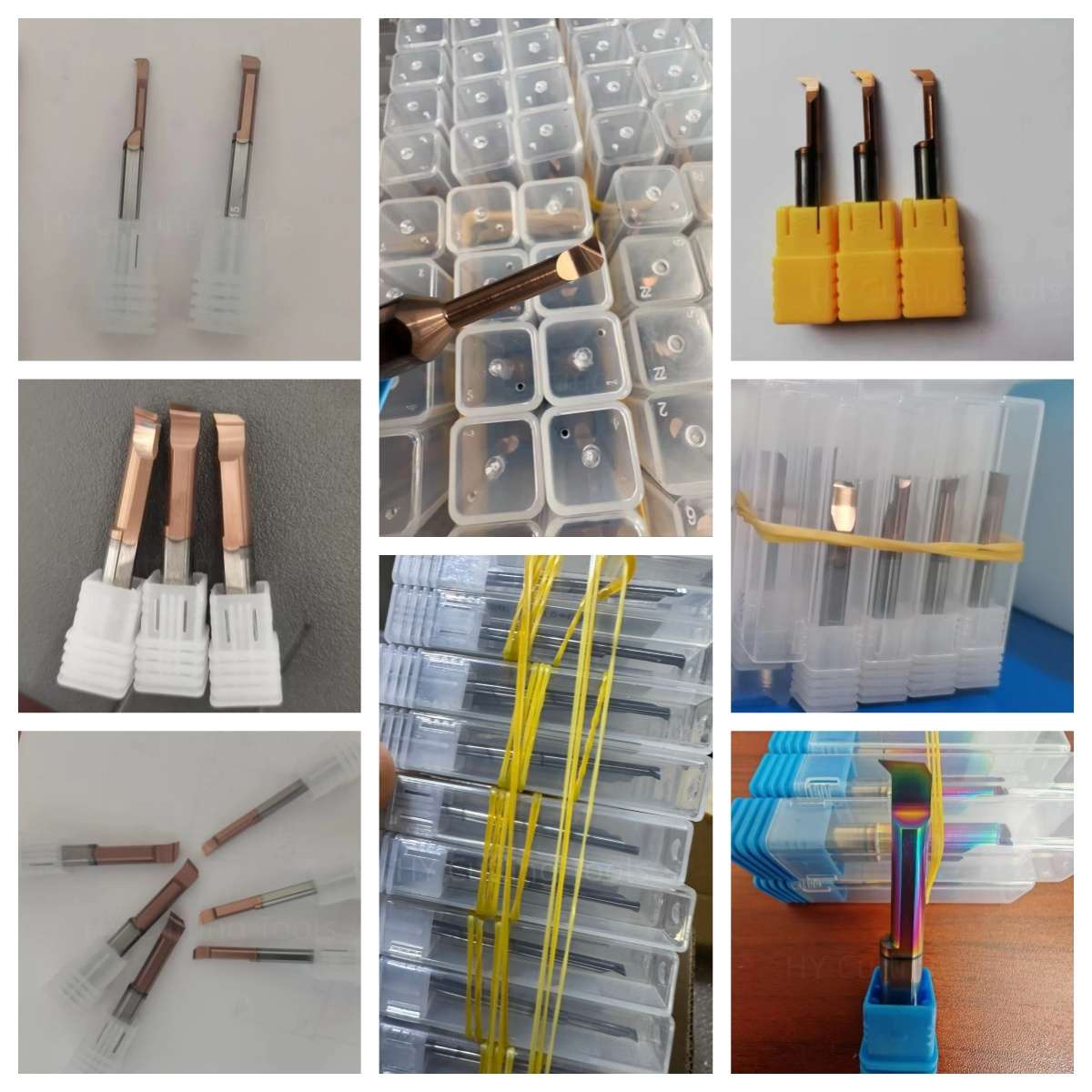
The images below show the MFL tool profile, cutting section, neck clearance, coated working area and solid carbide shank construction.

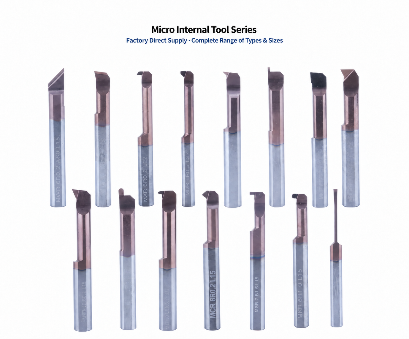
Micro Internal Tooling Video
View the tool construction and product details of our solid carbide micro internal tooling series.
Tool Nomenclature & Selection Guide
Select the suitable MFL left-hand micro face grooving bar according to tool series, shank diameter, groove width, working length and overall tool length.
| Kod | Açıklama | Example |
|---|---|---|
| MFL | Left-Hand Micro Face Grooving Bar | Left-hand cutting orientation |
| 60 / 80 | Şaft Çapı | Ø6 mm / Ø8 mm |
| B100 / B150 / B200 | Groove Width | 1.0 mm / 1.5 mm / 2.0 mm |
| L20 / L25 | Working Length | 20 mm / 25 mm |
| 50 / 60 | Toplam Uzunluk | 50 mm / 60 mm |
Dimensions & Available Sizes
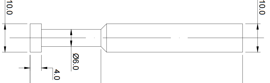
Confirm groove width, groove depth, minimum machining diameter, tool reach and shank diameter before selecting a standard model.
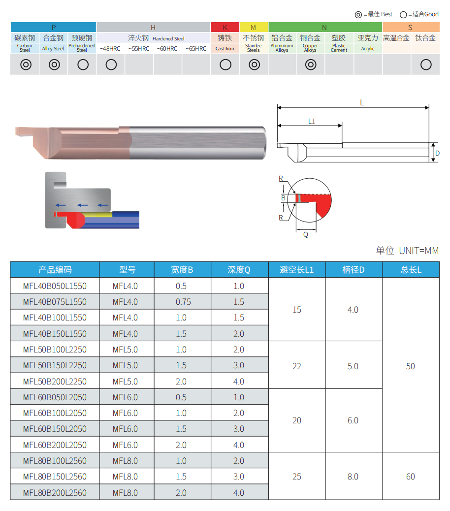
More groove widths, working lengths, shank diameters and customized configurations are available according to drawings and machining requirements.
Standard Size Range
| Model | Şaft Çapı. | Groove Width | Working Length | Toplam Uzunluk |
|---|---|---|---|---|
| MFL60B100L2050 | Ø6 mm | 1.0 mm | 20 mm | 50 mm |
| MFL60B150L2050 | Ø6 mm | 1.5 mm | 20 mm | 50 mm |
| MFL60B200L2050 | Ø6 mm | 2.0 mm | 20 mm | 50 mm |
| MFL80B100L2560 | Ø8 mm | 1.0 mm | 25 mm | 60 mm |
| MFL80B150L2560 | Ø8 mm | 1.5 mm | 25 mm | 60 mm |
| MFL80B200L2560 | Ø8 mm | 2.0 mm | 25 mm | 60 mm |
Recommended Selection Parameters
Machining Guidelines
Follow these setup and machining recommendations to improve cutting stability, groove accuracy and tool life when using solid carbide micro face grooving bars.
Securely clamp the tool before machining and keep the tool overhang as short as possible to reduce vibration and cutting-edge damage.
Set the cutting edge on the spindle centerline or up to 0.05 mm below it. Do not position the cutting edge above the centerline.
For face-grooving operations, begin at the larger groove diameter and progress toward the smaller diameter.
Apply suitable coolant and maintain effective chip evacuation to prevent chip packing, edge chipping and poor groove finish.
Use the tool for controlled radial face-grooving operations. Avoid lateral cutting or side turning unless the tool geometry is specifically designed for it.
Where machining conditions allow, begin with a cutting speed of 40 m/min or higher and keep the feed rate within 0.05 mm/rev.
Parameter Note: Actual cutting parameters should be adjusted according to the workpiece material, groove diameter, tool overhang, coating, coolant supply and machine rigidity.
Related Micro Face Grooving Series
Radius Face Grooving: MZR / MZL Series
Deep Face Grooving: MVR Series
Chip-Control Grooving: MFR-C Series
We support distributors, tooling suppliers and industrial partners with flexible OEM and private label solutions for micro internal tooling products. From laser marking and customized packaging to product identification and technical documentation, we help customers build their own tooling product lines with reliable manufacturing support.
OEM Product Scope
We provide OEM and private label manufacturing solutions for micro internal tooling products, supporting distributors and tooling suppliers with standard series, customized specifications and drawing-based production.
MPR series and customized small-diameter boring tools for precision internal machining and anti-vibration applications.
MIR/MIL series with customized thread profiles, dimensions and product identification requirements.
Internal grooving and special groove solutions for miniature precision components.
Non-standard dimensions, special geometries and customer drawing-based tooling solutions are available.

Customization Options
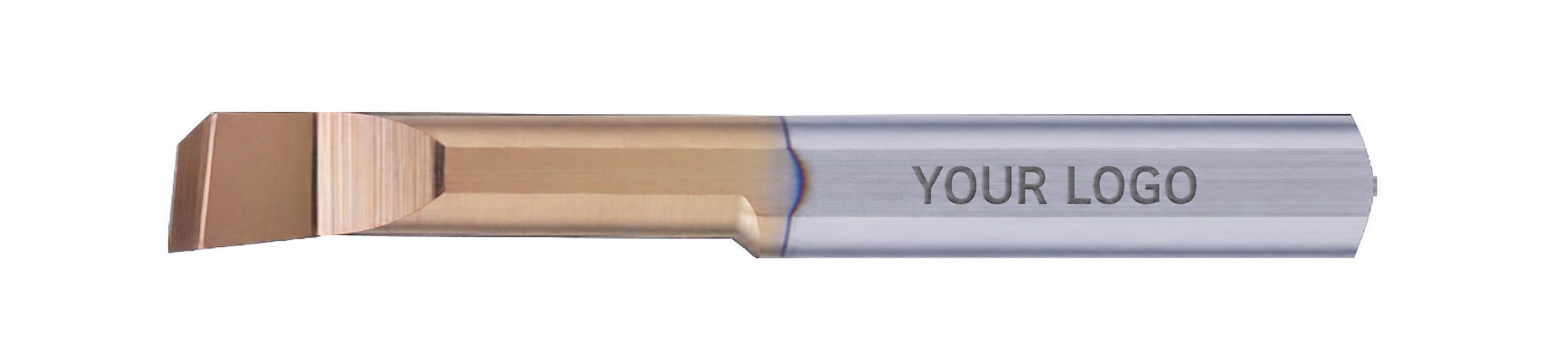
Laser Marking & Product Identification
Custom logo, model number and product identification marking can be provided according to distributor and brand requirements.
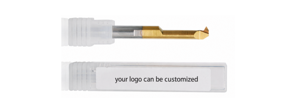
Custom Packaging
Individual packaging, labels and product information can be customized to support reseller sales channels and private brand development.
Technical Documents & Product Support
Support technical drawings, specifications and product information to help distributors promote and manage their tooling products.
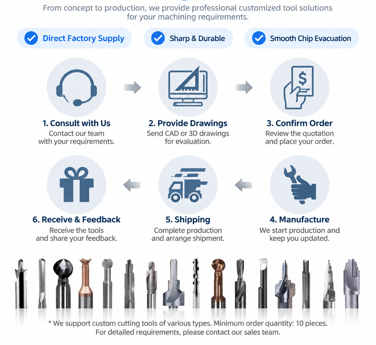
OEM Workflow
Confirm drawings, specifications, materials and packaging requirements.
Finalize tool design, marking details and production requirements.
Provide samples for testing and approval before batch production.
Produce and inspect according to confirmed requirements.
Private Label Support for Distributors
For distributors and tooling resellers, we provide flexible private label support including customized marking, packaging solutions and product documentation to help establish a professional tooling product range.
We follow strict quality control procedures from raw material inspection to final shipment. Each tool is inspected to ensure consistent dimensions, cutting performance and reliable quality for industrial machining applications.
Quality Control Process

Verify carbide material quality and consistency before production.
Control tool geometry, dimensions and cutting edge accuracy during manufacturing.
Inspect edge quality and surface finish to maintain stable cutting performance.
Confirm product specifications before packing and shipment.
Inspection Standards
| Inspection Item | Purpose |
|---|---|
| Material Inspection | Verify carbide quality and material consistency. |
| Dimension Inspection | Confirm tool size and tolerance requirements. |
| Cutting Edge Inspection | Check edge geometry and surface quality. |
| Final Inspection | Ensure products meet confirmed specifications before delivery. |
Packing & Protection

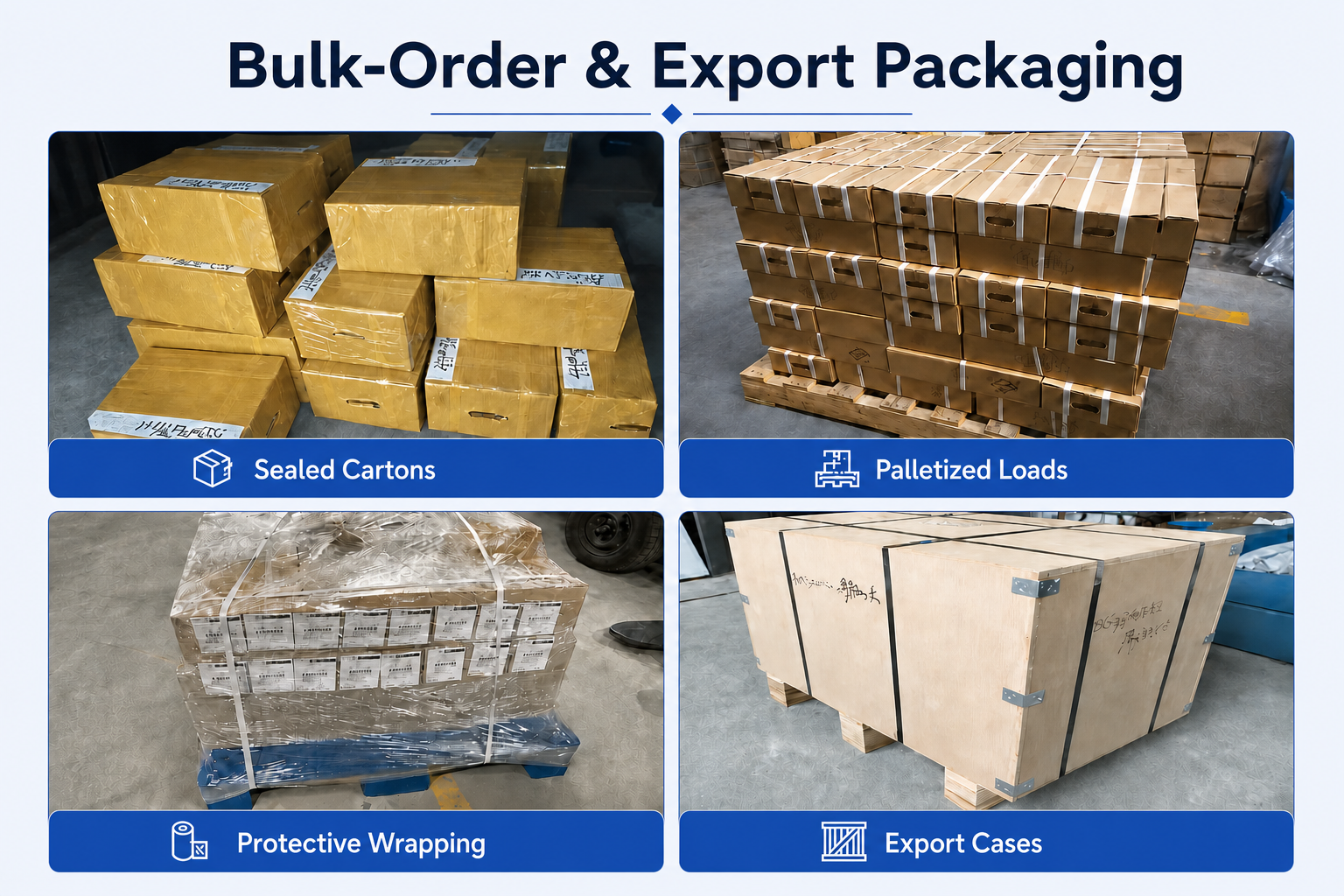
Individual protection and export packaging help prevent tool damage during storage and international transportation.
- Individual tool protection
- Product identification labels
- Batch traceability support
- Export shipment protection
Production & Delivery Workflow
Order Confirmation
Production Scheduling
Quality Inspection
Packing
Shipment

Delivery Support
Standard products can usually be shipped within 1–3 working days after order confirmation. Customized products require confirmation according to tool design, quantity and production requirements.
What are MFL micro face grooving bars used for?
Why does the MFL series use a left-hand cutting design?
What groove widths are available for MFL face grooving bars?
What materials can be machined with MFL micro face grooving bars?
Selection & Application FAQs
How do I select the correct MFL micro face grooving bar?
How can I confirm whether there is enough tool clearance?
How can I improve face-grooving stability in a small bore?
Ordering & OEM FAQs
Can you manufacture custom MFL face grooving bars?
Can I order small quantities or mixed MFL models?
What information is needed for an MFL quotation?
What is the lead time for standard and customized MFL tools?
Teknik Kaynaklar
Ölçüler, fiyatlar veya özel seçenekler mi arıyorsunuz?
Gerekli takım türünü, boyutlarını, miktarlarını, iş parçası malzemesini ve varsa OEM veya özel gereksinimleri bize iletin. Uygun teknik özellikleri, stok durumunu, teslim süresini ve fiyat teklifi ayrıntılarını size teyit edeceğiz.
Çizimler, boyut listeleri ve referans fotoğraflar memnuniyetle kabul edilir.