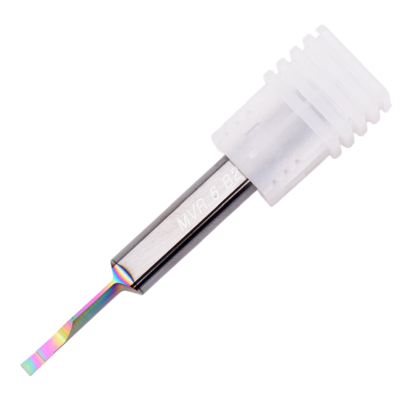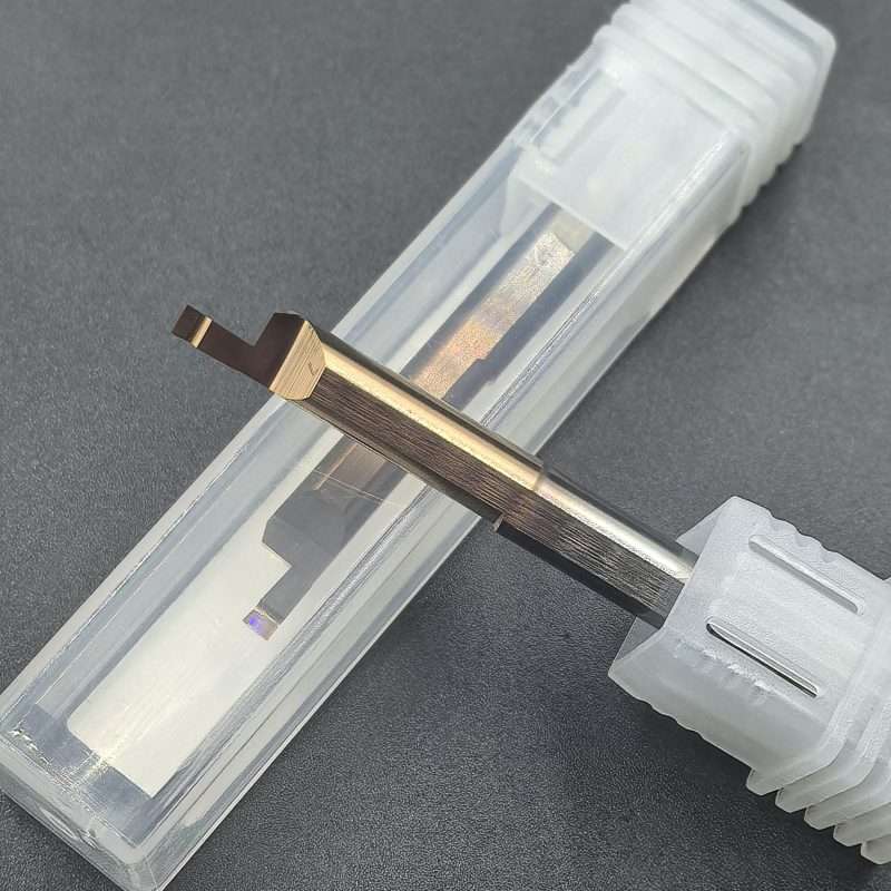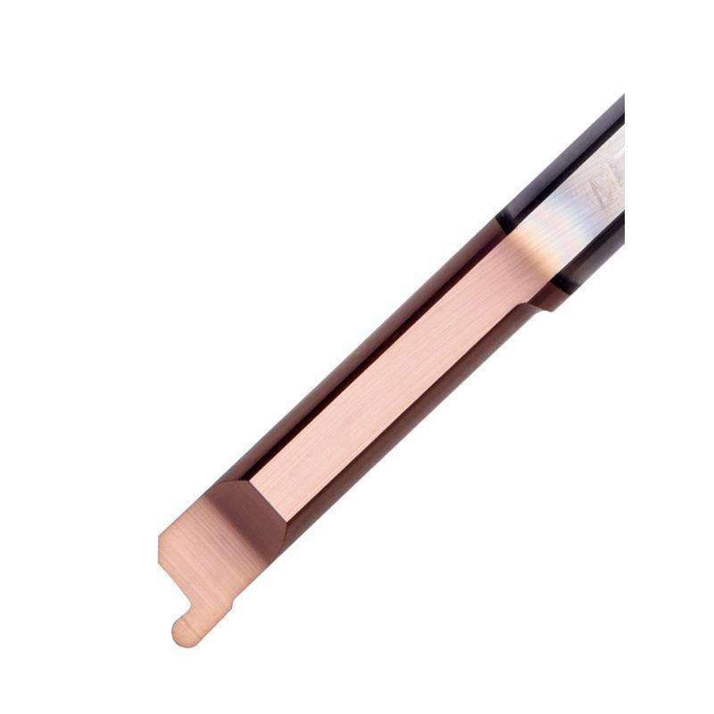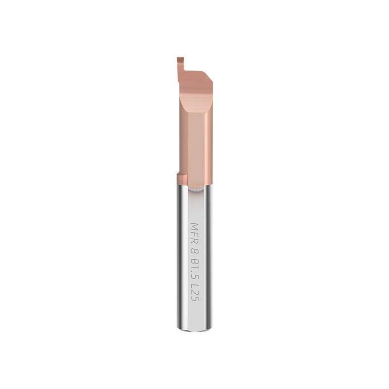
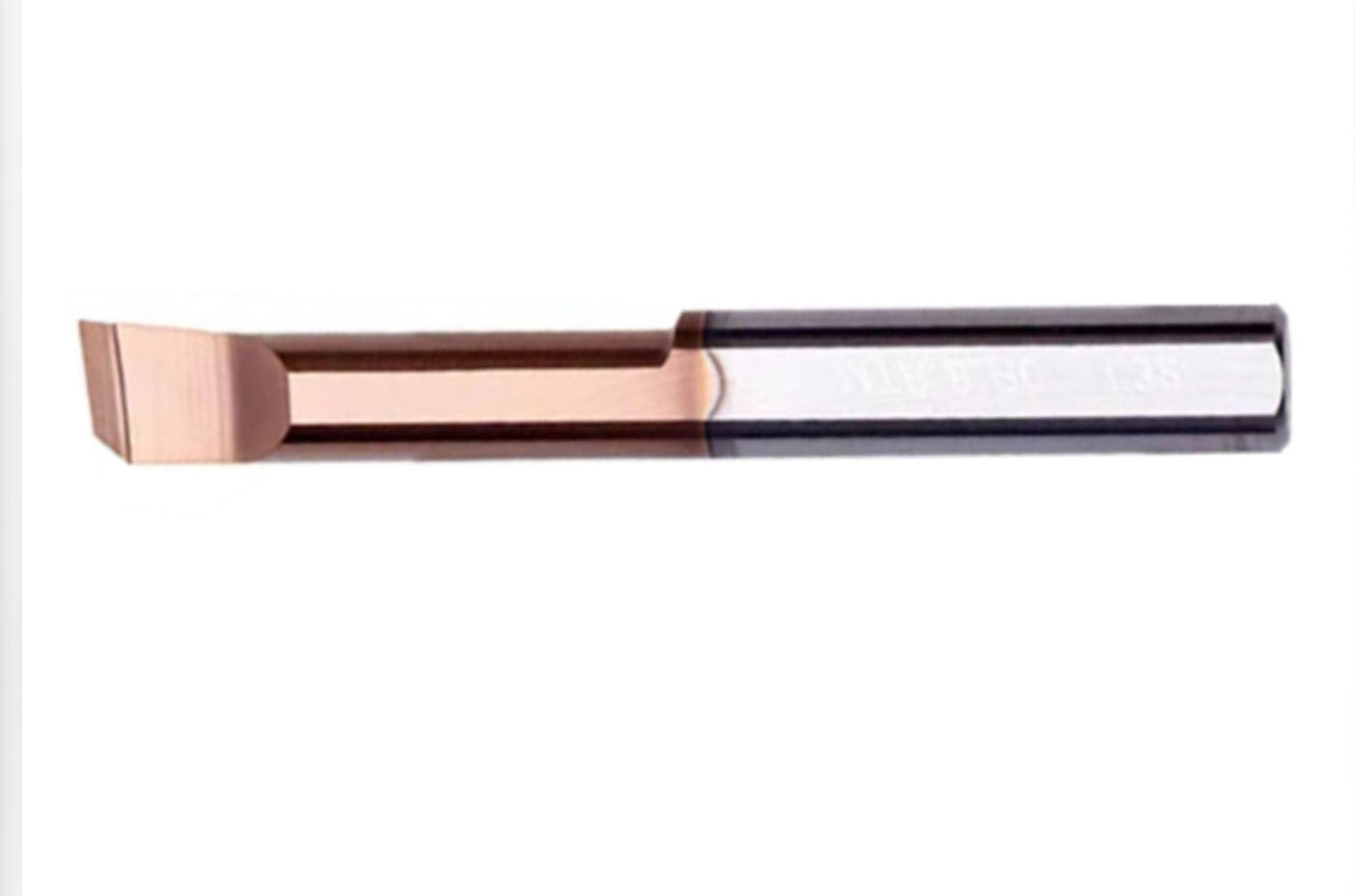
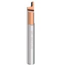
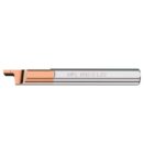


MFL Left-Hand Solid Carbide Micro Face Grooving Bars
Left-Hand Geometry
Small-Bore Access
Precision Grooving
Custom Sizes & OEM
MFL Left-Hand Micro Face Grooving Bars
MFL solid carbide micro face grooving bars are designed for left-hand internal face grooving in small bores. Compact cutting geometry provides access to recessed end faces, while precision-ground edges support groove-width control in CNC turning.
Micro Internal Tooling Series — Product Display
Left-Hand Access & Groove Control
Left-Hand Cutting Geometry
Matches tool approach and mounting arrangements that require a left-hand cutter.
Small-Bore Clearance
Compact cutting and neck geometry provide access to confined internal end faces.
Precision-Ground Grooving Edge
Controlled edge width supports repeatable face-groove dimensions and surface finishing.
Solid Carbide Construction
An integral carbide body provides support for small cutting sections and restricted-access turning.
Small-Bore Face Grooving Applications
Internal Annular Grooves
Face grooves in recessed ends of small turned components.
Sleeves & Precision Housings
Drawing-defined end-face features inside restricted bores.
Left-Hand Turning Setups
Operations requiring a compatible cutting orientation and holder arrangement.
Select Another Tool For: Radial internal grooving, boring or threading unless a separate geometry is specified.
MFL Model & Clearance Selection
Select the groove width, groove diameter range, depth and working length together. Confirm minimum bore access, adjacent-wall clearance and holder compatibility against the component drawing.
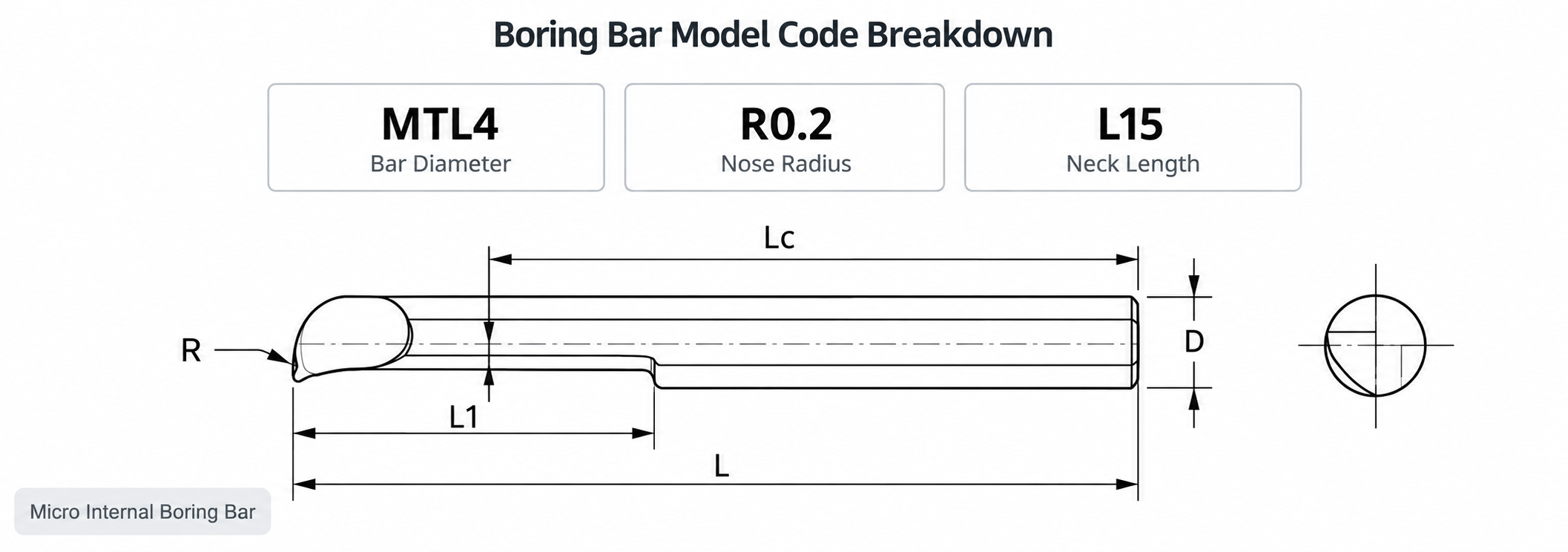
Left-hand identifies the tool orientation. Confirm cutting direction and spindle rotation for the actual mounting arrangement.
Workpiece Materials & Tool Configuration
Configurations can be reviewed for carbon steel, alloy steel, stainless steel, cast iron and selected aluminum or copper alloys. Cutting-edge preparation and coating are matched to the exact material, hardness and groove engagement.

MFL Cutting Profile & Product Details
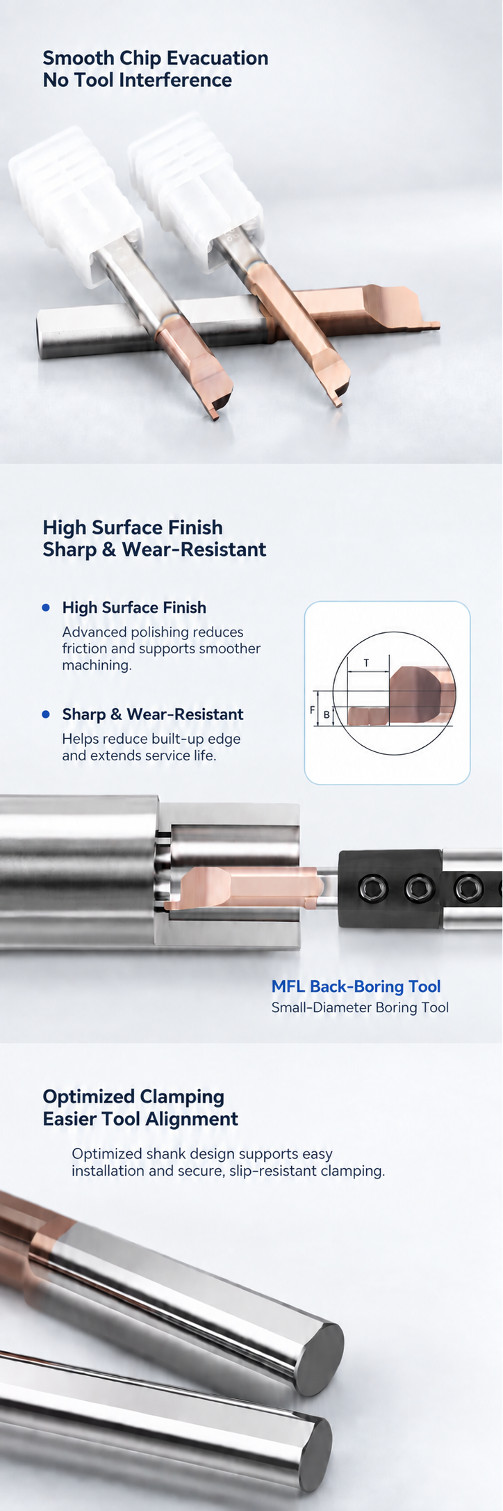

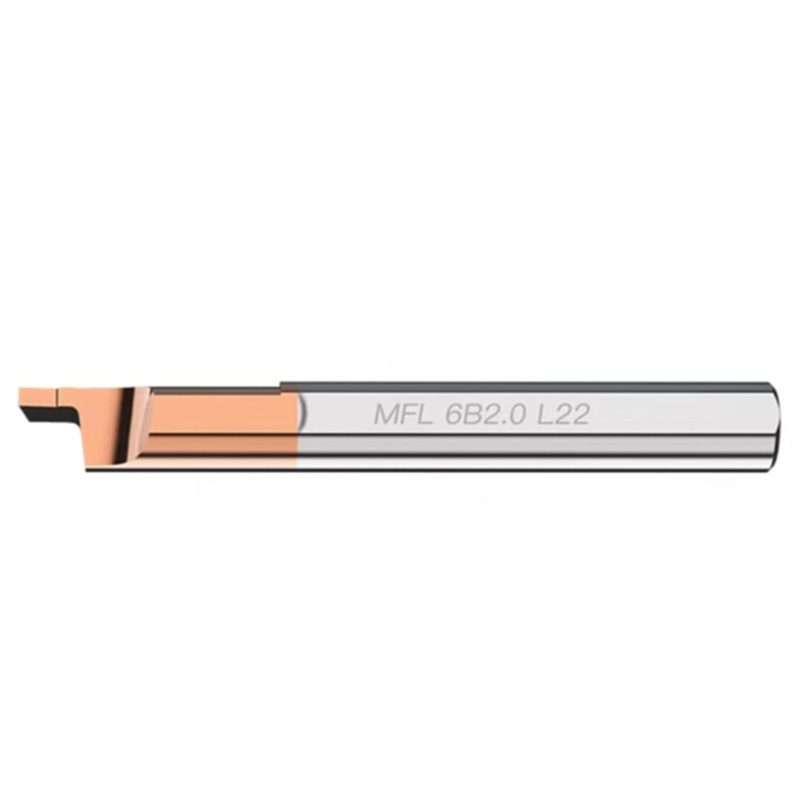
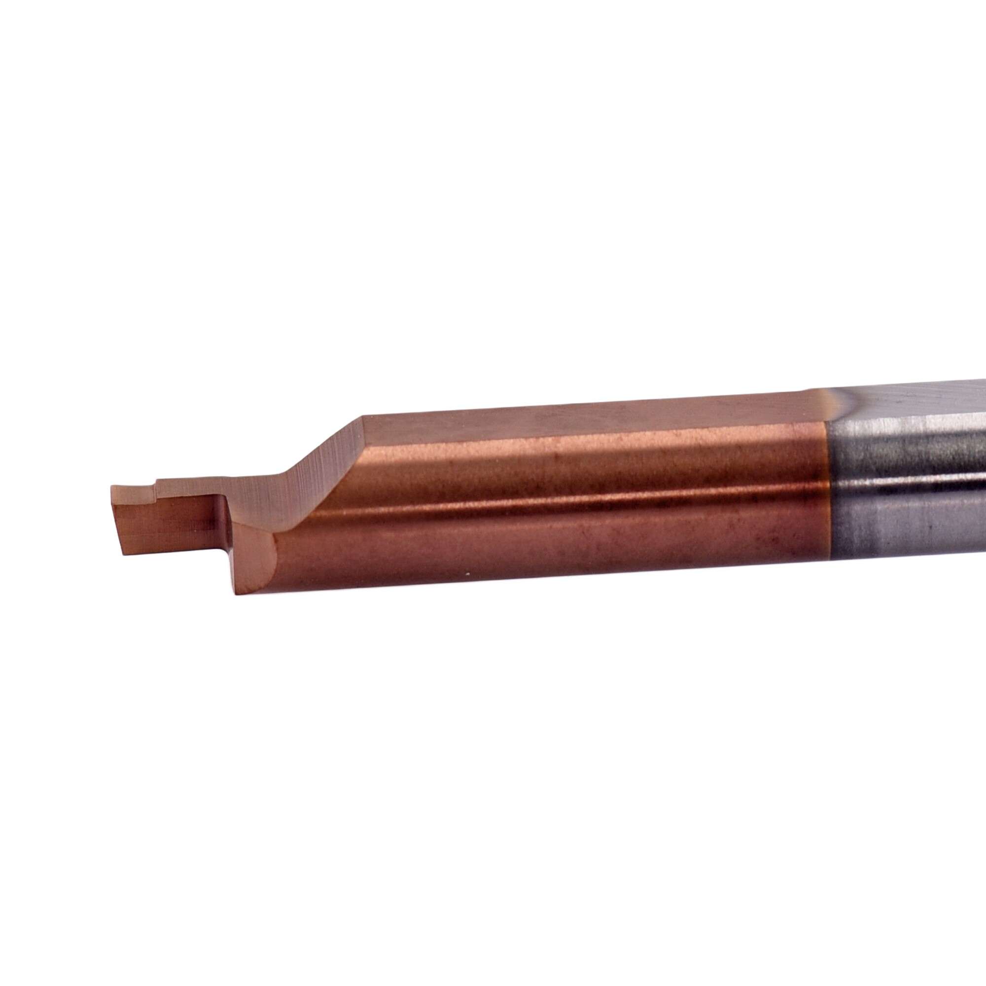
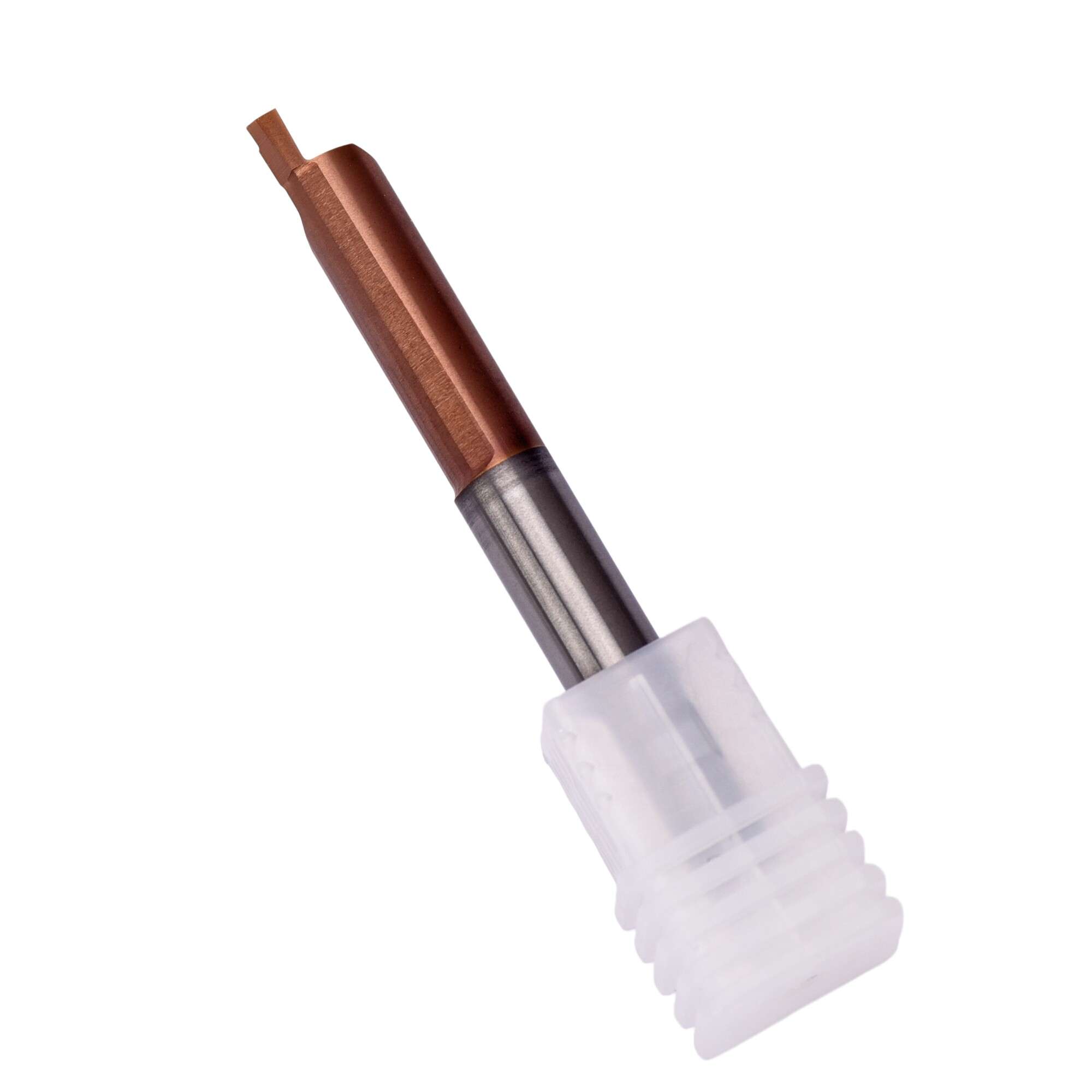
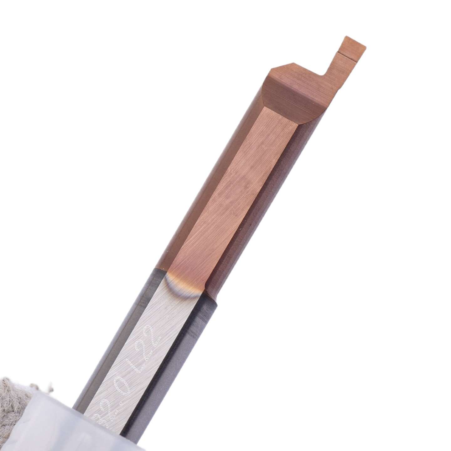
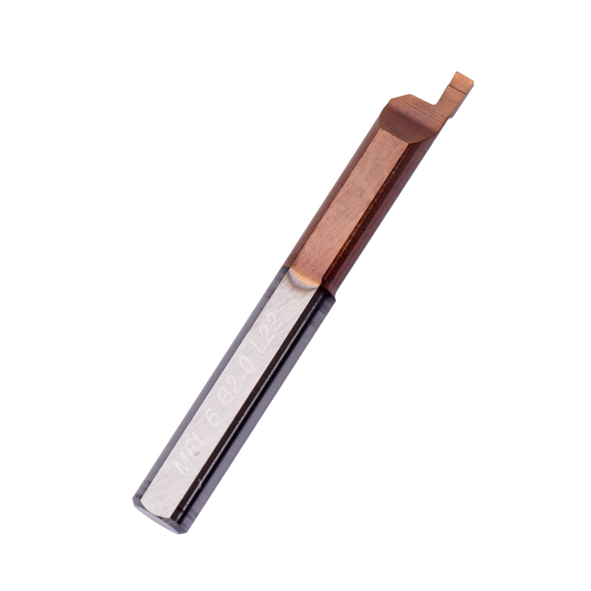
Custom MFL Tools & Series Selection
Custom groove widths, cutting profiles, working lengths, shanks and coatings can be reviewed from drawings. OEM identification and packaging support distributor programs and repeat orders.

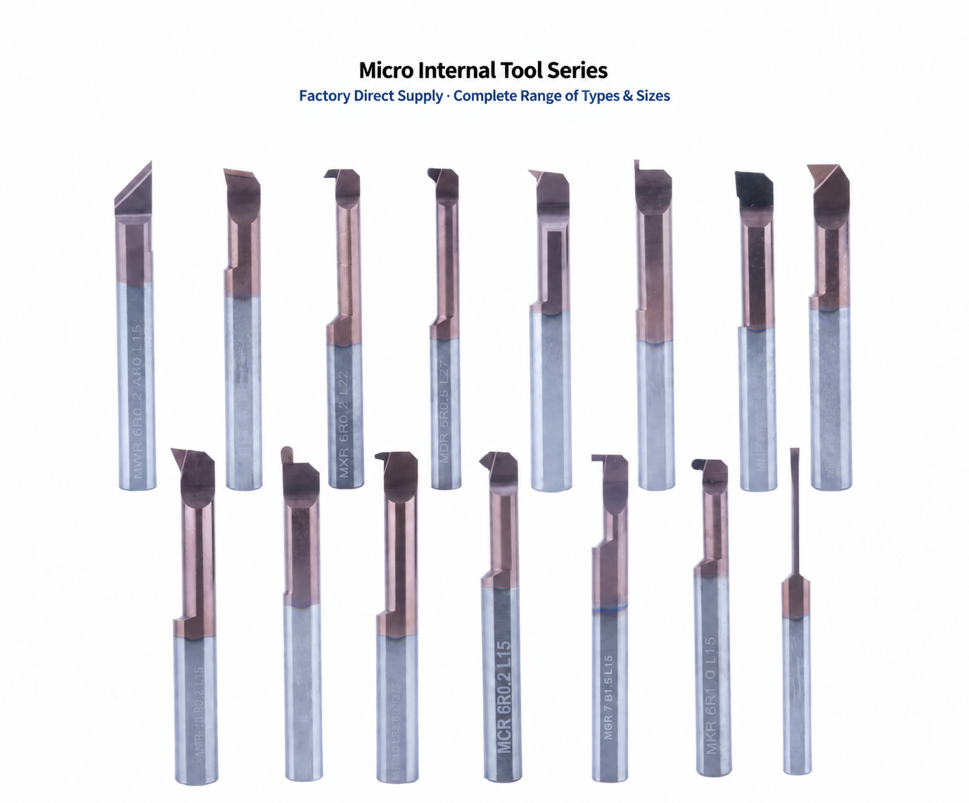
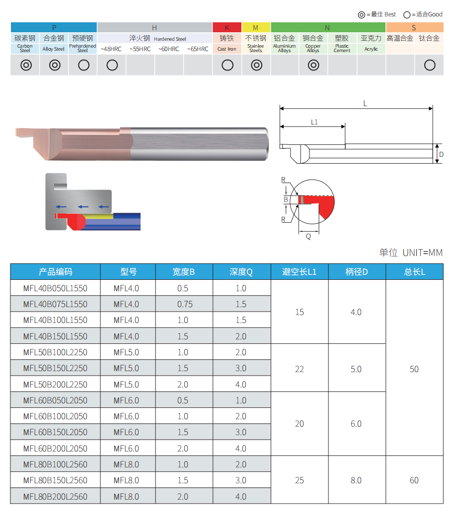
MFL Micro Face Grooving Bar Specifications
Reference sizes for MFL left-hand solid carbide micro face grooving bars. Select groove width, working length and shank size to suit the component geometry. All dimensions are in millimeters.
Standard Sizes
| Model | Shank Ø | Groove Width | Working Length | Overall Length |
|---|---|---|---|---|
| MFL60B100L2050 | 6 | 1.0 | 20 | 50 |
| MFL60B150L2050 | 6 | 1.5 | 20 | 50 |
| MFL60B200L2050 | 6 | 2.0 | 20 | 50 |
| MFL80B100L2560 | 8 | 1.0 | 25 | 60 |
| MFL80B150L2560 | 8 | 1.5 | 25 | 60 |
| MFL80B200L2560 | 8 | 2.0 | 25 | 60 |
Model example: MFL60B100L2050 = left-hand series · Ø6 shank · 1.0 groove width · 20 working length · 50 overall length.
Selection & Setup
- Groove geometry: Confirm width, depth, inner and outer groove diameters, and corner requirements.
- Access & clearance: Check minimum bore size, holder clearance and the complete entry and retraction path.
- Tool orientation: Match left-hand geometry to the holder position, cutting approach and spindle rotation.
- Machining setup: Minimize overhang and confirm center height, coolant supply and cutting parameters for the selected tool and material.
Related Face Grooving Tools
MZR / MZL — Radius Grooving MVR — Deep Face Grooving MFR — Face Grooving
Need the Right MFL Size or a Custom Tool?
Send your groove drawing, bore size, workpiece material and quantity for tool selection and a quotation.
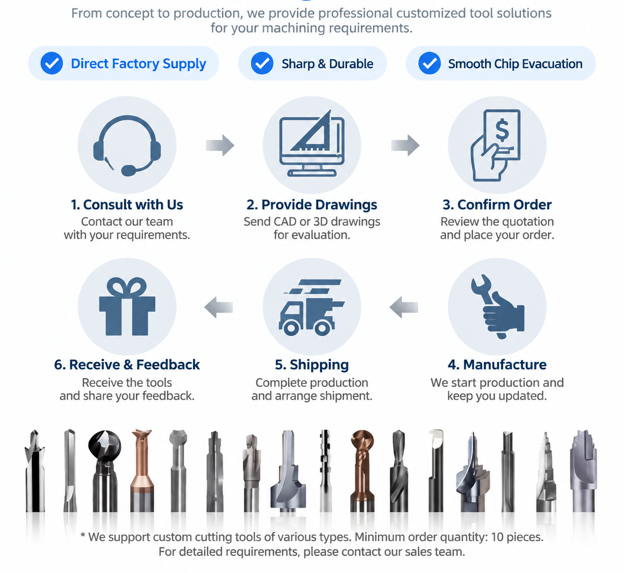
MFL Left-Hand Face Grooving Bar Customization
Custom groove widths, working lengths, shanks and cutting profiles are available for MFL left-hand micro face grooving bars, with OEM branding options.

OEM & Private-Label Options
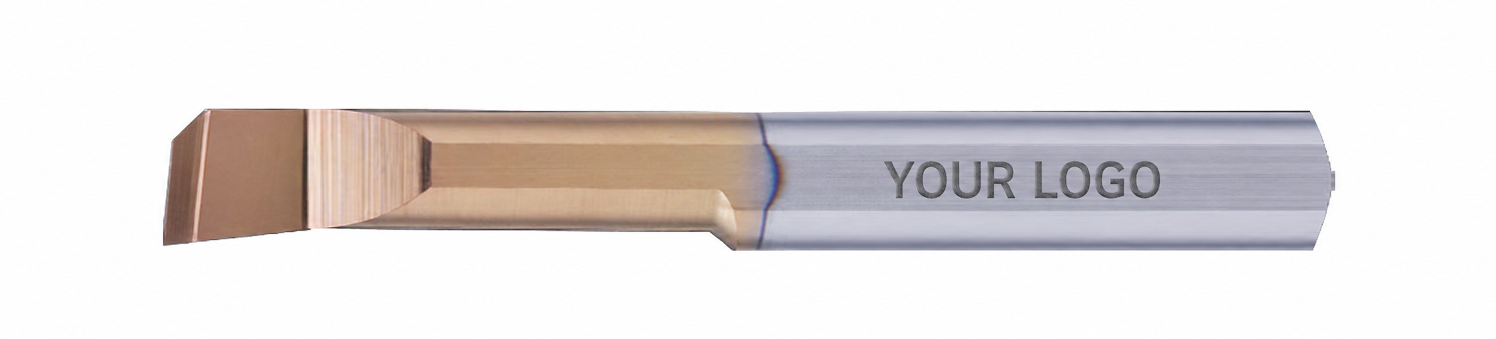
Laser Marking
Logos and model codes, subject to shank space.
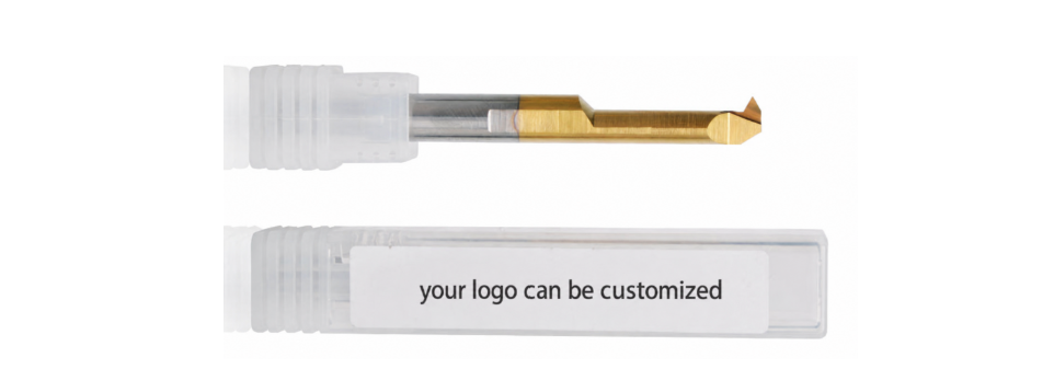
Private-Label Packaging
Branded labels and protective packaging.
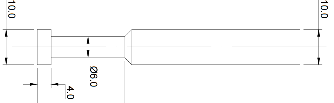
Drawings & Specifications
Approved dimensions for repeat orders.
Custom Order Process
Requirement review → Drawing approval → Samples where required → Production & inspection.
MFL Grooving Bar Quality & Delivery
Material verification, grinding control and final inspection support consistent MFL micro face grooving bar specifications for standard and repeat orders.

Key Inspection Points
- Material: Carbide grade and blank specifications.
- Dimensions: Groove width, working length, shank and overall length.
- Cutting geometry: Left-hand orientation, edge profile and grinding condition.
- Order identification: Model, marking and packaging details.
Inspection requirements follow the confirmed specification or approved drawing. Batch records can be arranged according to order requirements.
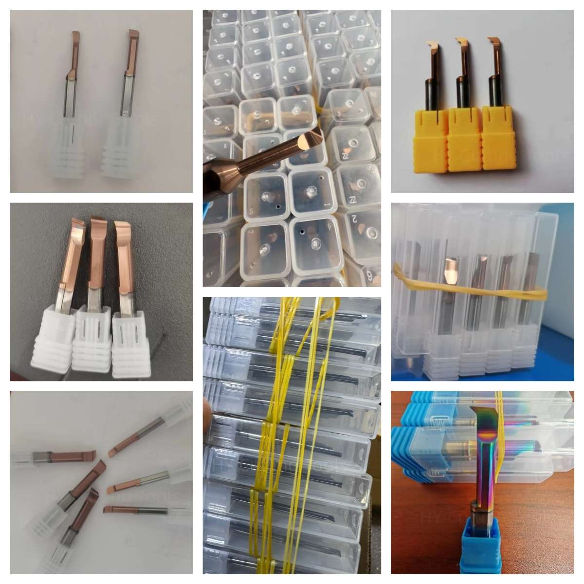
Tool Protection & Packaging
Individual protection, clear size labels and outer packing help protect cutting edges during storage and transport.


Lead Time & Shipping
Standard tools: Typically 1–3 working days, subject to stock.
Custom tools: Lead time confirmed by design, quantity and production requirements.

MFL Left-Hand Micro Face Grooving Bar FAQs
Is an MFL bar suitable for internal face grooves or bore-wall grooves?
Do I need a left-hand face grooving tool?
What groove widths and shank sizes are available?
Will the tool fit my bore and groove diameter?
Can MFL tools machine stainless steel or aluminum?
Custom Orders & Supply
Can I order custom groove widths or extended reach?
What is the MOQ, and can I mix MFL models?
What should I send for pricing and delivery confirmation?
Catalog & Selection Resources
Need Sizes, Pricing or Custom Options?
Send your specifications and quantity for a quote.
- Standard Sizes
- Small Trial Orders
- Mixed Sizes
- OEM & Custom
View QR Code – Contact Sales on WeChat

Scan to contact us on WeChat.
Scan to contact us on WeChat.