
U Drill Selection Guide: 9 Checks Before You Order
A U drill can match the requested diameter and still be wrong for the application. Hole depth, entry and exit conditions, spindle arrangement, coolant delivery and the exact insert system can all change the result.
Isso U drill selection guide gives machinists, buyers and tooling resellers nine checks for a new application or replacement. A body code, catalog page, drawing or clear photo can begin a review—but cannot confirm equivalence by itself.
U Drill Selection Guide: 30-Second Review
Use these checks to identify the missing information. Do not select a model from one row alone.
| Check | Confirm | Main risk if missed |
|---|---|---|
| 1. Drilling method | Diameter, tolerance, depth and production volume | Using an indexable drill where another method fits better |
| 2. Hole and component | Through/blind, entry, exit, intersections and wall strength | Uneven loading, burrs or an incomplete depth allowance |
| 3. Diameter and L/D | Usable depth and the shortest suitable body | Insufficient reach or unnecessary deflection |
| 4. Machine and shank | Tool rotation, holder, power, torque and alignment | Wrong interface, body rubbing or unstable hole size |
| 5. Insert system | Complete body, insert, position, screw and pocket data | False compatibility from a similar shape or code |
| 6. Workpiece material | Grade, hardness, condition and matching insert | Poor chip control or premature edge failure |
| 7. Coolant and chips | Internal/external supply, pressure, flow, filtration and chip path | Chip jamming, scoring or body damage |
| 8. Cutting data | Data for the exact body, insert, diameter and condition | Applying a broad material range as a machine setting |
| 9. Replacement approval | Drawing comparison, controlled trial and acceptance criteria | Calling a candidate tool an equivalent before testing |
Swipe to view all columns.
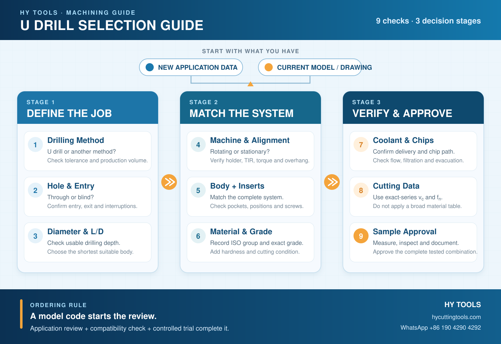
The nine checks can be grouped into three practical decision stages, as summarized below.
What Is a U Drill?
In everyday machining language, “U drill” usually refers to an indexable insert drill used for drilling from solid. Many common designs use a central insert and a peripheral insert. The central insert cuts around the drill axis, while the peripheral insert works at the outside diameter and strongly influences the finished hole wall.
The two positions do not experience the same cutting speed, load or chip formation. Sandvik Coromant’s official drilling guidance shows a characteristic centre chip and a turning-like peripheral chip. Do not assume both pockets use the same grade or geometry unless the system documentation allows it.
Check 1: Decide Whether a U Drill Is the Right Method
Start with the required hole, not the tool already in stock. Indexable, exchangeable-tip and solid carbide drills overlap in some applications, but differ in diameter range, precision, depth capability and replacement economics.
| Drilling method | Common strength | Verify before choosing |
|---|---|---|
| Broca U indexável | Replaceable edges and productive drilling, particularly as diameter increases | Hole capability, machine load, chip evacuation and insert compatibility |
| Exchangeable-tip drill | Replaceable head with drill-specific geometry and size control | Head-body interface, available sizes, permitted depth and runout |
| Solid carbide drill | Useful for small-to-medium diameters, precision and application-specific designs | Diameter, coolant, coating, regrinding policy and usable length |
Swipe to view all columns.
No industry-wide rule defines one starting diameter or maximum L/D for every U drill. These limits belong to the exact product family. Confirm hole capability before comparing cost and cycle time.
Check 2: Define the Hole, Component and Entry Condition
A useful application review records more than “Ø25 × 75 mm deep.” Confirm:
- Finished hole diameter, tolerance and surface requirement
- Drilled depth, bottom allowance and breakthrough distance
- Through, blind, stepped, pre-drilled or intersecting hole
- Flat, inclined, curved, cast or interrupted entry and exit
- Workpiece grade, hardness, condition and quantity
- Thin walls, weak sections or clamping limits near the hole
Irregular entries create uneven edge engagement. Sandvik’s irregular-surface drilling guidance recommends the shortest suitable drill and application-specific data reductions, with separate guidance for cross holes, inclined surfaces and pre-drilled holes.
Check 3: Match Diameter, L/D and the Shortest Suitable Body
L/D is drilling depth divided by nominal cutting diameter. A 3D body does not automatically provide 3D of usable depth in every component. Check the drawing for maximum drilling depth, overall length, shank, flute clearance and bottom or exit allowance.
Choose the shortest body that safely reaches the feature. Extra body length and overhang reduce stiffness and increase sensitivity to alignment, chip evacuation and vibration.
Check 4: Verify the Machine, Shank, Holder and Alignment
On a machining centre, the drill normally rotates. On a lathe, the workpiece may rotate while the drill remains stationary, changing the alignment and troubleshooting path.
| Setup item | What to verify | Possible symptom if missed |
|---|---|---|
| Stationary drill | Parallelism and tool centreline relative to the spindle axis | Oversize, undersize or funnel-shaped hole |
| Rotating drill | Holder, total indicator runout (TIR), spindle and clamping | Uneven wear, poor finish or reduced life |
| Machine capacity | Available torque, power and spindle-speed range | Stalling, excessive load or forced low productivity |
| Shank and interface | Shank diameter/length, flats or orientation, holder and coolant entry | Incorrect clamping, leakage or lost insert orientation |
| Tool overhang | Shortest safe gauge length and a rigid holder | Vibration, deflection or drill-body rubbing |
Swipe to view all columns.
For stationary drilling, follow a system-specific alignment procedure. Sandvik’s non-rotating drilling guide explains why centreline alignment, TIR and turret deflection must be checked rather than treated only as a speed-and-feed problem.
Check 5: Confirm the Complete U Drill Insert System
Insert shape is only the beginning. A comparison should identify the body, central and peripheral positions, complete insert designation, size, chipbreaker or geometry, carbide grade, screw and pocket.
Some suppliers use WC or SP in body codes, while compatible inserts may carry WCMX, WCMT or other designations. These are not universal performance grades, and a similar-looking trigon or square insert does not prove interchangeability. Seat support, thickness, edge preparation, chipbreaker, grade and body design all matter.
| Check | Evidence to request | Do not assume |
|---|---|---|
| Body system | Complete model and dimensioned catalog page | A similar diameter means the same pocket |
| Insert fit | Full insert code, dimensions and clear pocket photo | The first letters prove interchangeability |
| Position | Central/peripheral assignment in the maker’s data | Both pockets use identical grades or geometries |
| Fixação | Screw, wrench and tightening specification | A screw that threads into the body is correct |
| Aplicativo | Material, hardness, coolant and series cutting data | Shape or edge count alone defines performance |
Swipe to view all columns.
For WCMX or WCMT supply, review the HY Tools U-drill insert range, then confirm the exact drill body and insert position before ordering.
Check 6: Match Insert Geometry and Grade to the Workpiece
“Steel” or “stainless” is not specific enough. Record the grade, hardness, heat-treatment condition, cast or forged surface and whether cutting is continuous or interrupted. Then use the insert supplier’s application map.
| Material group | Common drilling concern | Verify before selection |
|---|---|---|
| ISO P — steel | Chip formation, edge wear and variable surface condition | Exact grade/hardness, chipbreaker, carbide grade and cutting continuity |
| ISO M — stainless steel | Long chips, adhesion, heat and work hardening | Sharpness, edge strength, coolant delivery and approved grade |
| ISO K — cast iron | Abrasive wear, dust and cast-skin variation | Wear resistance, surface condition and wet/dry guidance for the system |
| ISO N — non-ferrous | Built-up edge, burrs and material adhesion | Sharp or polished geometry, coating/uncoated option and coolant strategy |
| ISO S / H | High heat, hardness or edge-failure risk | Exact alloy/hardness and an application-approved drill and insert combination |
Swipe to view all columns.
Do not identify a coating from colour alone. Similar colours can represent different compositions, substrates and grades. Use the complete grade code and application data.
Check 7: Plan Coolant Delivery and Chip Evacuation
Chip evacuation is part of tool selection. Review chip length, flute space, hole orientation, coolant route, filtration, pressure and available flow.
Sandvik states that internal coolant is preferred to avoid chip jamming, particularly in long-chipping materials and holes deeper than 3×DC. It allows external coolant for shallow holes when chip formation is already good. Seco likewise links poor chip evacuation with incorrect dimensions and bad surface finish in its indexable drill guidance.
Do not make “add a peck cycle” the universal answer. First inspect both chip types, cutting edges, coolant outlets and the exact series guidance. Confirm any pecking strategy for that drill and material.
For ISO M applications, continue with our U drill for stainless steel guide.
Check 8: Set U Drill Cutting Data from the Exact Series
A material-only speed table is too broad to be called safe. Starting data must match the body, insert geometry, carbide grade, diameter and application. Record tool rotation, coolant supply and entry condition.
The standard metric calculations are:
Spindle speed: n = (1000 × vc) ÷ (π × Dc)
Feed rate: vf = n × fn
vc = cutting speed (m/min); Dc = drill diameter (mm); fn = feed per revolution (mm/rev).
For drilling, label feed as fn in mm/rev—not milling feed per tooth, fz. During a trial, inspect both chips, listen for interrupted cutting, monitor load, measure the hole and change one variable at a time within the supplier’s range.
Check 9: Review a Replacement Model and Approve the Sample
A tooling reseller may receive only a purchasing list and current model. That can start a review, but the result remains a candidate replacement pending dimensional, application and sample approval.
- Identify: record the complete drill body, central/peripheral inserts, screws, shank and coolant connection.
- Compare: place the original and candidate drawings side by side; check every interface and usable dimension.
- Fill the gaps: obtain material, hole, machine, coolant, tolerance and quantity where possible.
- Test: run a controlled sample with agreed cutting data, inspection points and stop criteria.
- Approve: record the accepted body, insert positions, parameters, life criterion and package label.
| Acceptance item | What to record |
|---|---|
| Hole geometry | Diameter at agreed positions, depth and relevant straightness or roundness result |
| Surface and exit | Surface-finish method/result, burr, breakthrough and visible scoring |
| Process stability | Chip form, evacuation, sound, spindle load and coolant condition |
| Tool condition | Central/peripheral wear, chipping, screw security and body rub marks |
| Economics | Cycle time, accepted holes per edge and cost per accepted hole |
Swipe to view all columns.
U Drill Troubleshooting: Check Evidence Before Changing the Insert
The same symptom can have different causes on a rotating drill and a stationary drill. Start with the process evidence rather than immediately changing the insert grade.
| Symptom | Verifique primeiro | Then review |
|---|---|---|
| Chip jamming | Chip form, coolant flow, filter and blocked outlets | Geometry and cutting data within the maker’s range |
| Oversize, undersize or tapered hole | Rotating/stationary setup, alignment, holder and body rub marks | Central/peripheral edge condition and seat cleanliness |
| Vibration | Overhang, workholding, turret or spindle stability | Cutting speed and application-specific insert geometry |
| Poor finish | Chip scoring, peripheral edge wear and coolant | Feed, stability and any secondary finishing requirement |
| Inconsistent life | Wear pattern on both inserts and coolant repeatability | Material batch, data, insert seats, screws and clamping |
Swipe to view all columns.
This sequence is consistent with Sandvik’s indexable drill troubleshooting guide. Use it as a diagnostic order, not as a substitute for the instructions for the selected tool system.
Prepare a Quote-Ready U Drill Inquiry
Use either route below. Complete application data is helpful, but do not delay an inquiry just because the end user has not supplied every item.
| Inquiry path | Send these details |
|---|---|
| New application | Material/hardness; hole diameter/depth; through or blind; entry/exit; tolerance/finish; rotating or stationary setup; machine, holder, coolant and quantity |
| Existing-model replacement | Brand and complete body/insert codes; catalog page or drawing; tool, pocket and label photos; current issue; quantity; known application data |
| Limited information | Send the current model, purchasing list or clear photos first. Mark unknown fields so they can be confirmed before final approval. |
Swipe to view all columns.
Perguntas frequentes
Is a U drill the same as an indexable drill?
U drill is commonly used as a market term for an indexable insert drill, but it does not define one universal insert or body standard. Confirm the exact product family and compatible components.
What information is most important when choosing a U drill?
Start with hole diameter, actual depth, tolerance, entry and exit conditions, workpiece material, rotating or stationary setup, machine capacity, coolant and production quantity.
Can WC and SP systems be compared by insert shape alone?
No. Supplier system codes and insert shapes do not by themselves establish compatibility, stability, chip control or cost per accepted hole. Compare the complete body, pocket, insert positions, geometry, grade and application data.
Do the central and peripheral pockets always use the same insert?
No universal rule applies. Some systems use the same basic insert family in both positions, while others specify different geometries or grades. Follow the documentation for the exact drill body.
Should a U drill use a peck cycle?
Do not apply pecking as a universal rule. Inspect chip formation and coolant first, then follow the recommendation for the exact drill series, material and hole condition.
Can a reseller request a replacement without complete machining data?
Yes. A complete current model, drawing, catalog page, purchasing list or clear photos can begin the review. Final equivalence still requires compatibility checks and, where appropriate, a controlled sample trial.