
How to Choose Solid Carbide End Mills: Flutes, Geometry, Coatings and Applications
Two buyers may request the same Ø8 mm four-flute solid carbide end mill and still need different tools: one for side milling pre-hardened steel, another for full-slotting stainless steel. The size matches; the applications do not.
This solid carbide end mill selection guide covers new applications and model replacements. A code, catalog page, drawing or clear photo can start a comparison—but cannot confirm equivalence.
Solid Carbide End Mill Selection Guide: Quick Table
Use these as starting directions, not universal rules. Final choice still depends on tool design, engagement, workpiece, machine and quality target.
| Aplicativo | Possible starting direction | Confirm before selection |
|---|---|---|
| Aluminum slotting | Lower flute count, open chip space and sharp, polished geometry | Alloy, slot depth, coolant, finish and surface treatment |
| Steel side milling | Supported square or corner-radius geometry with a suitable coating | Hardness, radial engagement, axial depth, reach and required corner |
| Stainless-steel slotting | Material-specific geometry with enough chip space | Grade, slot engagement, coolant delivery, rigidity and chip evacuation |
| Hardened-steel finishing | Short reach with application-specific geometry and coating | Actual hardness, stock allowance, runout, holder and machine stability |
| 3D contouring | Ball nose or an appropriate corner radius | Surface shape, effective cutting diameter, step-over, tilt and finish target |
| Heavy stock removal | Roughing-specific geometry matched to the toolpath | Machine power, engagement, chip path and finishing allowance |
| Deep cavity or rib | Reduced- or long-neck tool with only the required reach | Wall clearance, neck diameter, reach, deflection and holder interference |
Swipe to view all columns.
For more application-based comparisons across cutting-tool families, visit the HY Tools Guias de seleção de ferramentas.
The selection process can be organized into seven practical checks, as summarized below.
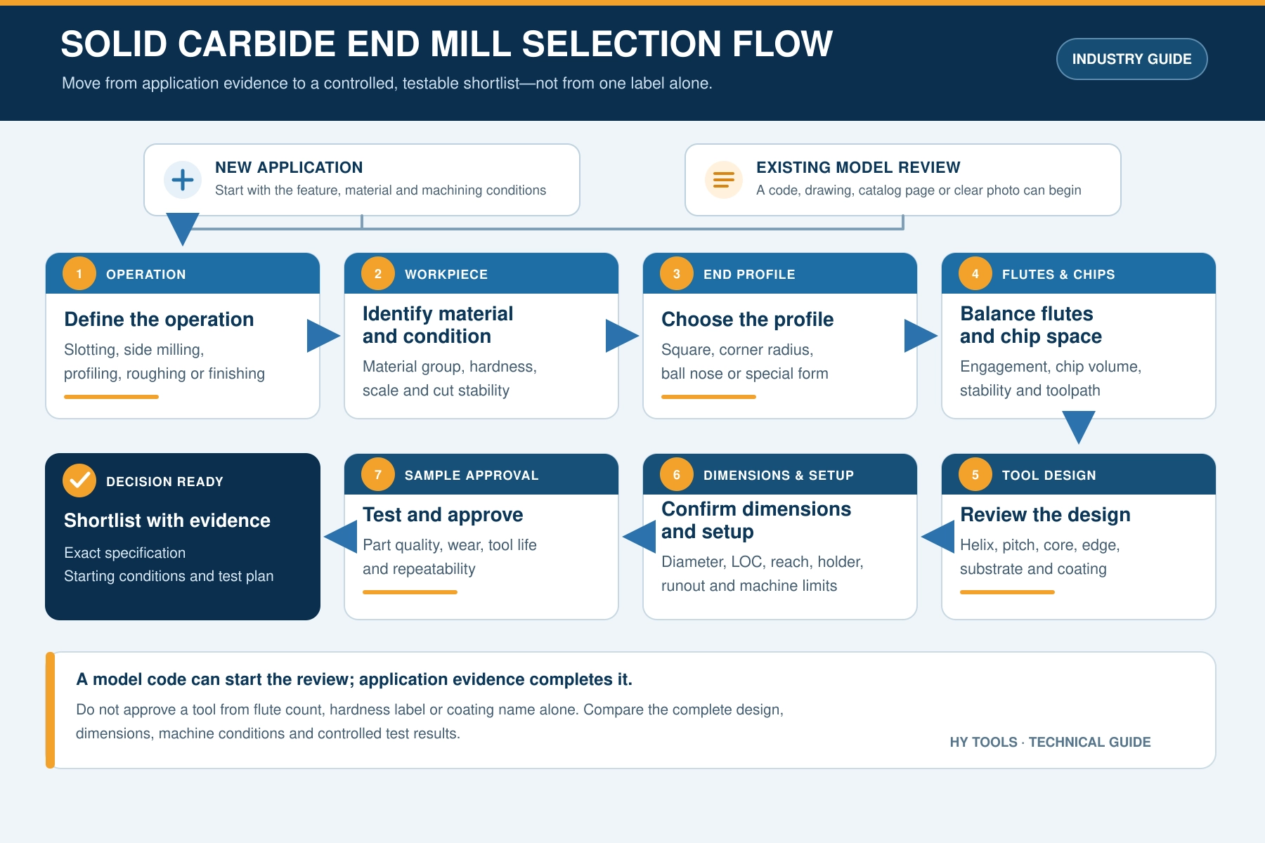
1. Define the Material and Milling Operation
Full slotting, side milling, pocketing, roughing, finishing and 3D profiling expose the same diameter tool to different engagement, chip volume and cutting forces.
Full slotting machines three faces and restricts chip exit. Sandvik Coromant’s slot-milling guidance treats rigidity, overhang and chip evacuation as limits. Do not apply light side-milling data unchanged to a full-width slot.
Record these items before narrowing the tool:
- Workpiece grade, hardness and condition
- Milling operation and tool entry
- Axial depth (ap) and radial engagement (ae)
- Feature dimensions, corner and finish
- Machine, holder, coolant and chip removal
2. Choose the Correct End Mill Profile
Match the end profile to the finished feature, not only to expected tool life.
| Profile or design | Typical use | Important limitation |
|---|---|---|
| Square end mill | Slots, shoulders, flat-bottom features and general side milling | The sharp tool corner has less support than a suitable corner radius |
| Corner-radius end mill | Profiling and shoulder milling needing more corner support | Leaves a radius at the floor-to-wall transition |
| Ball nose end mill | 3D surfaces, molds, cavities and curved profiles | Cutting speed approaches zero at the tool center; effective diameter matters |
| Roughing end mill | High stock removal with serrated chipbreakers or strategy-specific smooth-edge geometry | Engagement, chip form, surface and finishing allowance depend on the design |
| Long-neck or reduced-neck end mill | Deep walls, ribs and features below surrounding geometry | Extra reach reduces rigidity and increases setup sensitivity |
Swipe to view all columns.
For ball-nose machining, use the effective diameter in cut; Sandvik’s profile guide warns about near-zero center speed. See our corner-radius e ball-nose guides.
3. Select the Flute Count from Engagement and Chip Space
Flute count balances available chip space, the number of cutting edges and the complete cross-section of the tool. It is not a hardness code.
| Flute-count direction | What it can provide | Where to be careful |
|---|---|---|
| Lower flute count | More chip space; often useful for full slots, high chip volume and non-ferrous materials | Fewer teeth per revolution; core strength still depends on cross-section |
| Intermediate flute count | A practical balance for many slots, side cuts and profiles | Still needs geometry matched to material and engagement |
| Higher flute count | More effective teeth can raise feed per revolution at a suitable feed per tooth | Less chip space and potentially higher resistance; engagement still limits the choice |
Swipe to view all columns.
Mitsubishi Materials notes that more cutting edges narrow flute spacing, worsening chip discharge and increasing resistance. It generally favors fewer edges for wide engagement, slotting or low-rigidity setups. Compare the full design, not a 2F-versus-4F rule.
See our 4-flute end mill guide for a focused example.
Profile and flute count solve different parts of the selection problem, as shown below.

4. Check Helix, Pitch, Core and Cutting-Edge Geometry
Two four-flute end mills can behave differently because flute count describes only one feature.
| Geometry feature | What it influences | Atenção ao selecionar |
|---|---|---|
| Helix angle | Shearing action, cutting resistance, axial force and surface generation | A higher helix can sharpen cutting action but also increase axial force |
| Pitch, variable pitch and variable helix | Tooth-entry timing and harmonic excitation | Can help reduce chatter but cannot correct poor workholding, runout or excessive overhang |
| Core diameter / web thickness | Tool cross-section, rigidity and flute-pocket volume | A thicker core supports rigidity but reduces room for chips |
| Rake and relief | Cutting force, edge support, rubbing and heat | The sharpest edge is not automatically the most durable edge |
| Edge preparation | Sharpness, coating support, chipping resistance and adhesion | Polished, sharp and honed edges serve different materials and loads |
| End-face and center-cutting geometry | Plunge entry, ramping, helical interpolation and pocket access | Center cutting alone does not define drilling capability or the allowable ramp angle; check the exact model |
Swipe to view all columns.
Mitsubishi shows that helix angle changes sharpness and force direction, while too much can weaken the edge. Kennametal’s chatter guidance also checks core diameter, overhang, holder balance, runout, relief, fluting and helix.
5. Match Carbide Substrate and Coating to the Application
A coating cannot compensate for the wrong profile, inadequate chip space or unstable setup. Select substrate, edge and coating as one system.
Solid carbide is not a single grade. WC grain size and binder content influence hardness, toughness, wear resistance and edge integrity, as Hyperion explains. Because grade names are manufacturer-specific, “micrograin” or an HRC label alone does not prove equivalence.
| Grupo de peças | Prioridades de seleção | Questions to confirm |
|---|---|---|
| Steel and alloy steel | Edge support, wear resistance and chip control | Grade, hardness, engagement, coolant and interruption |
| Aço inoxidável | Edge support, chip evacuation and heat control | Exact stainless grade, slot/side cut, coolant and work hardening risk |
| Ferro fundido | Abrasion resistance and supported edges | Grey/ductile type, scale, interruption and dry/wet strategy |
| Alumínio e ligas não ferrosas | Sharp edge, low adhesion, smooth flute and chip space | Alloy/silicon content, finish, coolant and surface option |
| Titanium and nickel alloys | Dedicated geometry, stable engagement and heat control | Exact alloy, toolpath, coolant delivery and machine stability |
| Hardened steel | Short reach, controlled runout and edge integrity | Actual hardness, stock allowance, finishing strategy and holder accuracy |
Swipe to view all columns.
Oerlikon Balzers describes TiAlN- and AlTiN-based coatings as hard and wear-resistant, but with different thermal and friction properties. Carbon-based coatings and polished uncoated tools serve selected non-ferrous applications; follow the exact specification.
Which HY Tools End Mill Series Fits Your Application?
Compare starting options for our HRC45, HRC55, HRC65 and aluminum end mill series. Then check the exact model, geometry and application before making a final selection.
See our fresas de alumínio e stainless-steel guide for material-specific starting points.
6. Check Dimensions, Reach and Rigidity
Choose the shortest cutting length and reach that complete the feature safely. Extra flute length extends the lower-rigidity fluted section, while additional overhang magnifies deflection.
| Dimension | Por que isso é importante |
|---|---|
| Cutting diameter | Defines feature and toolpath limits, affects stiffness, and sets the rpm required for a target cutting speed |
| Length of cut (LOC) | Must cover the axial cutting depth without adding unnecessary flute length |
| Overall length (OAL) | Affects machine and holder fit but does not equal usable cutting reach |
| Shank diameter and tolerance | Must match the holder; tolerance and concentricity affect clamping accuracy and total indicated runout |
| Reach / length below shank | Determines access below surrounding geometry |
| Neck diameter and length | Control wall clearance and reduced-neck stiffness |
| Corner or ball radius | Must match the drawing, toolpath and inspection method |
Swipe to view all columns.
Use the largest diameter permitted by the feature and programmed engagement—not merely physical clearance. Near-matching internal corners can cause sudden engagement; precision slots may need an undersized tool and finishing passes.
In a simplified cantilever model, deflection rises with the cube of overhang. Mitsubishi shows that doubling overhang under the same load and geometry can produce about eight times the deflection. Actual results also depend on diameter, neck, holder and load.
If a standard end mill cannot provide the required diameter, reach, neck clearance, corner radius or cutting profile, a custom end mill can be reviewed from your drawing, existing tool or machining requirements.
7. Review the Machine, Holder and Milling Process
Review spindle capability, holder, runout, workholding, coolant and toolpath.
- Minimize tool stick-out and use an undamaged, clean holder.
- Verify runout, especially for micro end mills.
- Keep chips out of slots and deep pockets; recutting can damage both tool and surface.
- Confirm whether the exact end mill supports plunging, ramping or helical entry.
- Adjust data when engagement, reach or rigidity differs from catalog conditions.
- Use starting speeds and feeds for the exact series, then monitor chip formation, sound, spindle load and wear.
When diameter, flute count or engagement changes, do not copy rpm and table feed unchanged. Use milling formulas to recalculate rpm from cutting speed and diameter, and table feed from feed per tooth, effective teeth and rpm. Then adjust for reach, rigidity and chip evacuation; at low radial engagement, check radial chip-thinning guidance.
Once the end mill geometry and application have been confirmed, use the HY Tools speeds and feeds resources as a starting reference for cutting speed, RPM, feed per tooth and depth of cut. Adjust the starting values for the actual tool model, workpiece, engagement, overhang, coolant and machine rigidity.
8. Compare an Existing Solid Carbide End Mill Model
A common replacement enquiry contains only “Ø8 × 20 × 8 × 60, 4F, HRC55.” This can shortlist candidates, but cannot approve equivalence. Identical nominal dimensions can hide different corners, flutes, core, edge preparation, coating and tolerances.
| Comparison group | What to check |
|---|---|
| Identity | Current manufacturer, complete code, revision, catalog page and package label |
| Dimensões | Diameter and tolerance, LOC, OAL, shank, reach, neck and corner/ball radius |
| Geometria | Profile, flute count, cutting and helix direction, entry capability, pitch and edge preparation |
| Aplicativo | Workpiece grade and condition, hardness, operation, toolpath, engagement, machine, holder, coolant and current data |
| Replacement target | Cost, second source, availability, tool life, finish or problem correction |
| Commercial requirement | Quantity by size, trial, packaging, marking and repeat demand |
Swipe to view all columns.
With incomplete information, compare visible data and list the gaps. Keep candidate replacement wording until dimensions, application limits and test results are reviewed.
An existing code or nominal size can begin a comparison, but equivalence requires the checks below.

9. Test and Approve the Candidate End Mill
Before testing, define the goal, dimensional and surface limits, tool-life endpoint, and planned part count or cutting time.
For a drop-in replacement, keep the program unchanged only after confirming that its conditions fall within the candidate’s recommended range. For a performance comparison, keep the workpiece, machine, holder, overhang, coolant and toolpath consistent, but optimize each tool within its recommended range. Record every change.
| Evaluation area | What to record |
|---|---|
| Part quality | Feature size, corner/profile, burrs, surface finish and dimensional stability |
| Process stability | Sound, vibration, spindle load, chip formation and chip evacuation |
| Tool condition | Wear location, built-up edge, coating wear, chipping and breakage |
| Productivity | Cycle time, feed, tool changes and accepted parts |
| Repeatability | Results across multiple components and, where practical, tools |
| Commercial result | Cost per accepted component and re-order suitability |
Swipe to view all columns.
Not breaking is not enough. If size, finish or stability misses the requirement, review the setup, parameters and wear before bulk approval.
10. Prepare a Quote-Ready End Mill Inquiry
Complete data is valuable but not required for the first message. Use the path matching what you have.
| Inquiry type | Send first | Confirm before approval |
|---|---|---|
| New application | Material and condition, hardness, operation, feature dimensions, diameter, depth, reach and quantity | Machine, holder, coolant, engagement and quality target |
| Existing-model replacement | Brand, complete code, catalog page, dimensions and quantity | Application limits, replacement target and sample criteria |
| Limited information | Clear end, flute, shank and package photos plus known dimensions | Missing geometry and end-customer application data |
| Custom or private-label request | Drawing/reference, sizes, volume, marking and packaging | Manufacturability, inspection, trial and specification |
Swipe to view all columns.
HY Tools supports standard, mixed-size, small-batch and custom orders. Review our supply support e inspection process.
You can also review the Catálogos e downloads page for the Solid Carbide End Mills Catalog and the Solid Carbide End Mills Speeds & Feeds Guide.
Common Solid Carbide End Mill Selection Mistakes
- Selecting by hardness before defining the operation
- Treating 2F-for-aluminum and 4F-for-steel as universal
- Assuming more flutes always mean a stronger tool
- Ignoring radial engagement when moving from side cutting to slotting
- Mismatching corner radius to floor-to-wall geometry or finishing allowance
- Using nominal ball diameter instead of effective diameter
- Choosing unnecessary flute length, reach or overhang
- Identifying coating from color or an HRC label
- Expecting helix or coating to fix runout and workholding
- Calling tools equivalent from size, price or appearance
- Approving tool life after part quality has failed
Perguntas frequentes
How many flutes should a solid carbide end mill have?
No universal number applies. Fewer flutes generally provide more chip space; more flutes add effective edges. Match the count to material, engagement, chip volume, rigidity and geometry.
Is a four-flute end mill always best for steel?
No. Four flutes suit many steel side cuts, but full slots, weak setups, chip volume or specialized toolpaths may favor another design.
Do HRC45, HRC55 and HRC65 identify the coating?
No. They are supplier-defined application labels, not standardized coating or carbide-grade designations. Check the exact series’ substrate, coating, geometry, workpiece range and limits.
Are two end mills equivalent if the dimensions are the same?
No. Helix, flute form, core, corner, edge preparation, substrate, coating and tolerance may differ. Treat it as a candidate until reviewed and tested.
Can I request a quotation with only a current model code?
Yes. Send the manufacturer, complete code, quantity and catalog or package information. We can start the dimensional review and identify missing application details.