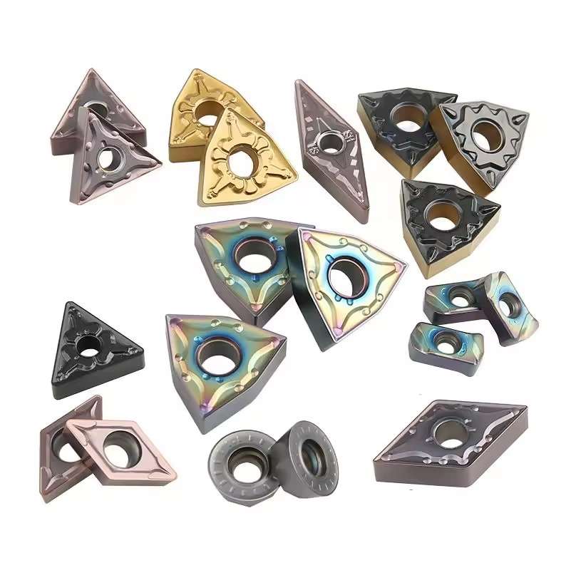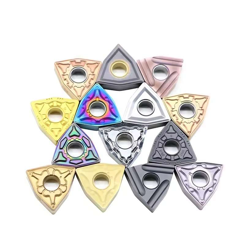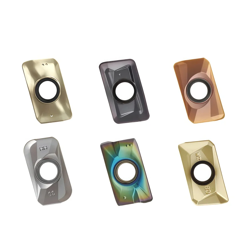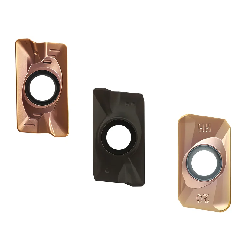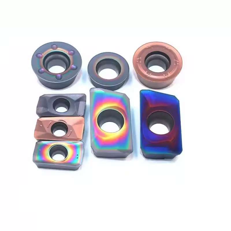


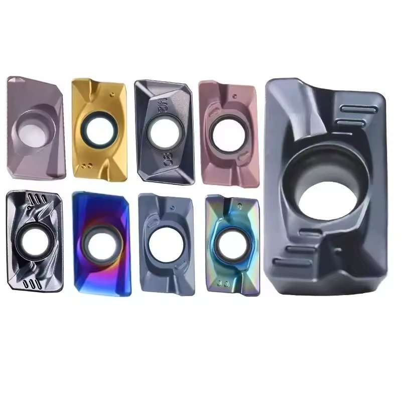


APMT 1135 Coated Carbide Milling Inserts for Steel and Stainless Steel
APMT 1135 coated carbide milling inserts are designed for shoulder milling, face milling, slotting and general-purpose CNC machining of steel and stainless steel. Positive cutting geometry helps reduce cutting resistance, while application-matched coatings provide wear resistance and edge stability. Multiple chipbreakers and grades support different machining loads and surface-finish requirements.
Consistent Quality
Consistent geometry across repeat orders.
Flexible Orders
Small batches and mixed sizes available.
OEM Support
Custom marking, labels and packaging.
Standard & Custom
Standard sizes and custom configurations.
◆Product Overview
The APMT 1135 Coated Carbide Milling Insert is a positive-relief indexable insert developed for shoulder milling, face milling, slotting, side milling, and profile machining with compatible APMT cutter bodies. Its coated carbide substrate is selected to balance cutting-edge strength, wear resistance, and heat control when machining steel and stainless steel.
Because steel and stainless steel generate different cutting conditions, the correct substrate, coating, edge preparation, and chipbreaker should be chosen for the actual material and operation. For a combined size comparison, see the APMT1604 / APMT1135 R0.8 milling insert series.
Coated Carbide
Steel & Stainless Steel
Indexable Milling

◆Understanding the APMT 1135 Designation
APMT 1135 identifies the basic insert family and size, but it does not fully define the cutting application. The suffix, chipbreaker, corner preparation, tolerance, coating, and carbide grade must also match the cutter pocket and workpiece.
Insert Shape Family
The first character identifies the standardized insert-shape family used by the compatible cutter pocket.
Positive Relief
Positive clearance helps the cutting edge enter the workpiece with lower rubbing and cutting pressure.
Tolerance & Type
These characters relate to dimensional tolerance and insert construction; the matching pocket remains essential.
Size Family
The numeric portion identifies the nominal insert-size family. Confirm actual dimensions from the supplier drawing.
◆Insert Series & Geometry Reference

Use the product image together with the full model code and cutter-pocket drawing when checking compatibility.
◆Why Coated Carbide for Milling?
Protect the Cutting Edge
A correctly selected coating helps resist flank wear and abrasive contact during repeated production milling.
Maintain Edge Stability
Coating and substrate work together to maintain hardness and reduce thermal damage at the cutting zone.
Support Repeatable Production
Stable edge condition improves dimensional consistency and helps reduce unplanned insert changes across a batch.


◆Steel vs. Stainless Steel Selection
One insert grade should not automatically be treated as equally suitable for every ferrous material. Steel prioritizes wear resistance and edge strength, while stainless steel requires sharp cutting action, controlled heat, and reliable chip evacuation.
| Selection Point | Steel | Stainless Steel |
|---|---|---|
| Primary Concern | Wear resistance and edge strength | Heat, adhesion, and work hardening |
| Edge Preparation | Balanced or reinforced edge according to load | Sharper positive edge with sufficient toughness |
| Chipbreaker | Selected for roughing, medium cutting, or finishing | Designed to shear cleanly and control long, tough chips |
| Coating / Grade | Wear-oriented selection based on cutting speed and interruption | Tough, low-friction, heat-resistant selection for the alloy |
| Programming Focus | Stable engagement and appropriate chip load | Avoid rubbing, dwell, and repeated passes that work-harden the surface |
For additional process guidance, read
how to prevent tool burning when machining stainless steel.
◆Recommended Milling Operations


◆Compatibility Checklist Before Ordering
If the existing tool uses another insert family, compare the broader
CNC turning and milling carbide insert range
before requesting an equivalent model.
◆Additional Product Details


◆Common Milling Problems & Checks
| Observed Problem | Possible Cause | What to Check |
|---|---|---|
| Premature Flank Wear | Speed too high or grade too soft | Verify material group, cutting speed, coating, and coolant strategy |
| Edge Chipping | Impact, vibration, weak edge, or unstable pocket | Check holder runout, cutter screws, machine rigidity, feed, and edge preparation |
| Built-Up Edge | Rubbing, low speed, unsuitable coating, or poor chip flow | Confirm chip load, sharpness, coolant delivery, and material-specific grade |
| Long or Recut Chips | Incorrect chipbreaker or insufficient evacuation | Review chipbreaker, engagement, coolant direction, and cutter flute space |
| Poor Surface Finish | Runout, worn edge, unstable setup, or incorrect feed | Inspect every insert seat, edge height, holder condition, and finishing allowance |
◆Related Inserts & Technical Resources
APMT1604 / APMT1135 R0.8 Inserts
Compare two common APMT size families for steel, stainless steel, and cast-iron milling.
LNMU / ENMU / BLMP Inserts
Consider double-sided high-feed geometry when productivity and shallow axial engagement are the main priorities.
Carbide Insert Types Explained
Review insert shapes, clearance styles, ISO workpiece groups, chipbreakers, and common selection mistakes.
CNC Turning & Milling Inserts
Browse APMT, CNMG, DNMG, SNMG, TNMG, VNMG, and WNMG carbide insert families.
Send the Complete Insert Code for Compatibility Checking
Provide the cutter-body model, complete insert designation, current grade or box label, workpiece material and hardness, machining operation, cutting depth, coolant method, machine condition, and order quantity. The correct APMT1135 chipbreaker, carbide grade, coating, and edge preparation can then be evaluated.
◆Specifications & Size Chart
APMT 1135 identifies the insert body family and size, while the full suffix and carbide grade identify the supplied cutting configuration. In the supplied APMT series chart, the H2, M2 and PM rows for APMT 1135 share the dimensions below. Values are in millimeters; confirm pocket fit and the actual coated grade from the complete ordered code.
| Model Reference | Suffix Shown | Length l | Width d | Thickness t | Corner R |
|---|---|---|---|---|---|
| APMT 1135–H2 | H2 | 11 mm | 6.35 mm | 3.5 mm | 0.8 mm |
| APMT 1135–M2 | M2 | 11 mm | 6.35 mm | 3.5 mm | 0.8 mm |
| APMT 1135–PM | PM | 11 mm | 6.35 mm | 3.5 mm | 0.8 mm |
◆APMT 1135 Designation
| Code | Meaning / Selection Check |
|---|---|
| A | 85° parallelogram insert shape. |
| P | 11° nominal clearance angle; positive-relief insert body. |
| M | Tolerance-class designation; use the supplier drawing for actual tolerances. |
| T | Insert hole / construction code; verify the hole and clamping form against the cutter pocket. |
| 1135 | Nominal size family; use the dimensions above for the listed variants. |
| Suffix + grade | Chipbreaker, cutting-edge preparation, coating and substrate require the complete supplier order code. “M2” as a variant suffix does not mean M2 high-speed steel. |
◆Material & Milling Application
| Selection Field | Details to Confirm |
|---|---|
| Steel · ISO P | State the exact carbon/alloy steel grade, hardness, scale and interrupted-cut conditions; select the suitable carbide grade and edge strength. |
| Stainless steel · ISO M | State the exact grade, such as 304 or 316, condition and coolant plan; check sharpness, adhesion control, heat resistance and chip evacuation. |
| Coating / grade | Coated carbide is the stated product type. Confirm the actual grade and coating system for the full insert code; no single coating is specified by “APMT 1135.” |
| Shoulder / face milling | Use a compatible cutter body; check pocket seat, insert projection, cutter diameter and recommended engagement. |
| Slot / ramp / helix | Only when the specific cutter body permits the operation; confirm slot depth, ramp angle, chip clearance and coolant access. |
◆How to Select the Insert
◆Starting Cutting Data
Obtain Vc, fz, axial depth (ap) and radial width (ae) from the supplier's recommendation for the complete grade and cutter body. Steel and stainless steel require separate starting settings. The insert-size code and photos alone do not provide validated cutting parameters.
◆Related Series & Resources
For a second insert-size family, compare the APMT 1135 / APMT 1604 R0.8 series. Our Carbide Insert Types Guide explains insert-family selection.
Send the full insert and cutter-body codes to confirm grade, coating, fit and availability.
◆Carbide Insert Customization & OEM
Specify the insert around the machining operation, workpiece and holder. We can review standard replacements, application-specific geometry and private-label requirements using your insert designation, drawing or sample. Available grades, coatings, dimensions and order quantities are confirmed for each requested series.
Geometry & Chip Control
Review chipbreaker, rake, cutting-edge preparation, nose radius and corner design for the operation and workpiece. Confirm holder compatibility before approving a modified geometry.
Substrate & Coating
Select an available carbide grade and coating for the workpiece material, cutting conditions and desired balance of wear resistance and edge toughness.
Dimensions & OEM
Review insert size, thickness, locating and clamping features, tolerances, laser marking and private-label packaging against the approved specification.
◆Customization Options
Use the fields below when sending an inquiry. The exact options depend on the insert family and are confirmed in the quotation or approved drawing.
| Specification | Details to Confirm |
|---|---|
| Insert Type | Turning, milling, threading, grooving or drilling insert; send the designation or drawing. |
| Size & Fit | Shape, size, thickness, inscribed circle or edge length, hole or clamping form, and holder model. |
| Cutting Geometry | Chipbreaker, nose or corner radius, edge preparation, cutting direction and application-specific profile. |
| Grade & Coating | Workpiece group and grade, carbide substrate, coating system and wet or dry cutting conditions. |
| Tolerance & Inspection | Critical dimensions, profile requirements, inspection method and any required report. |
| OEM Presentation | Insert or box marking, label content, packaging format and quantity per pack. |
◆How to Request a Custom Insert

Send your insert requirements through our contact form or review our OEM and private-label service.
◆Carbide Insert Quality Control

Insert quality depends on the approved grade, geometry, coating and dimensional specification. We review the requirements at order confirmation and align the inspection scope with the insert series and any customer drawing. Share critical dimensions or documentation needs before production so they can be included in the agreed inspection plan.
01 · Incoming Material
Confirm the specified carbide grade or material documentation against the order requirements.
02 · In-Process Checks
Review dimensions and cutting-edge features during production against the approved specification.
03 · Final Inspection
Check the agreed dimensions, appearance, edge condition, coating identification and marking as applicable.
04 · Packing Review
Verify the item code, quantity, labels and protective packing against the approved order.
◆Inspection & Documentation
Inspection points and acceptance criteria should be agreed for the ordered series. For custom inserts, the approved drawing takes priority over a generic catalogue description.
| Check Area | What to Confirm |
|---|---|
| Dimensions & Fit | Insert size, thickness, corner radius, clamping features and any drawing tolerances. |
| Cutting Geometry | Chipbreaker, edge preparation, usable corners and profile where applicable. |
| Grade & Coating | Approved grade and coating designation; any requested verification method. |
| Appearance & Packing | Visible edge damage, marking, item code, count and packing format. |
| Requested Records | Inspection report, material or coating documentation, sample approval or batch identification when agreed. |
◆Order & Delivery
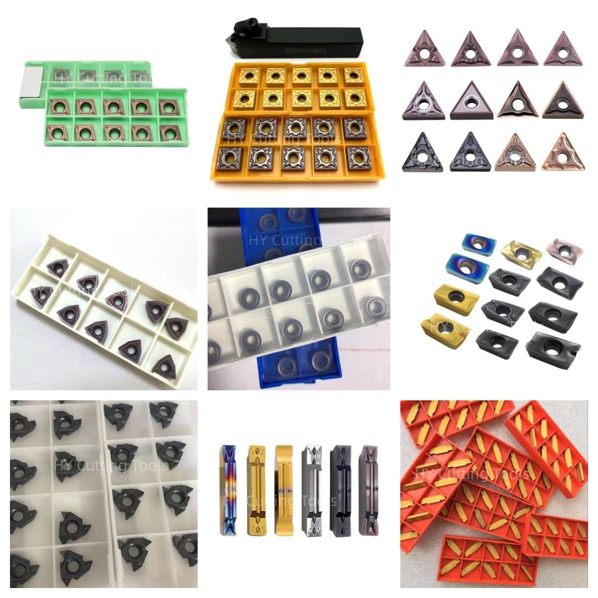

Share a line-by-line list of insert codes and quantities for a mixed-size quotation. Stock status, minimum quantity, sample requirements and production lead time are confirmed for each grade, coating and configuration.
Send your item list and quality requirements through our contact form for specification, availability and delivery confirmation.
◆Product FAQs
What does APMT 1135 identify?
APMT identifies an 85° parallelogram insert with 11° nominal clearance, M tolerance class and T construction/hole code. The 1135 portion identifies the size family. It does not specify a unique carbide grade, coating, chipbreaker or finished cutting edge; order by the full designation.
What dimensions are listed for APMT 1135?
The supplied series chart lists l = 11 mm, d = 6.35 mm, t = 3.5 mm and R = 0.8 mm for its APMT 1135 H2, M2 and PM rows. These are chart references; confirm the hole, tolerances and seating details using the specific product drawing.
Can the same coated insert mill steel and stainless steel?
Some coated grades may cover both ISO P steel and ISO M stainless steel, but the suitable grade, edge preparation and parameters must be verified for each workpiece. Specify the actual alloy, hardness, cutter body, coolant and operation when requesting a recommendation.
Do H2, M2 and PM indicate different steel grades?
They are model-variant suffixes shown in the reference chart. Their precise geometry and application range depend on the supplier's full designation. “M2” here is not a declaration that the carbide insert is made from M2 high-speed steel.
Is APMT 1135 suitable for slotting and ramping?
Shoulder and face milling are common uses with a compatible cutter. Slotting, ramping or helical entry require the cutter maker's approval and limits for axial depth, ramp angle and chip clearance. The insert designation alone cannot establish these capabilities.
How should I select cutting speed and feed?
Request grade-specific Vc and feed per tooth for the exact steel or stainless-steel grade, cutter diameter, tooth count and engagement. Start within that published range, then check chip formation, wear, chatter and surface finish during a trial cut.
◆Ordering & OEM FAQs
Will any APMT 1135 insert fit my milling cutter?
Match the complete insert code against the cutter's approved insert list. Check the pocket, seating surface, screw, hole form, corner radius, cutting hand and chipbreaker. A shared APMT 1135 size name alone does not prove fit.
What should I send for an equivalent-insert request?
Provide the existing manufacturer's complete insert code and grade, box-label photos, front and back insert photos, cutter-body code, workpiece grade, cutting conditions, current wear problem and required quantity. Compare fit and cutting results with a sample before repeat purchasing.
Can I combine grades or chipbreakers in one order?
Send a line-by-line list with each complete insert code and quantity. Mixed-model availability, minimum quantity, pack count and lead time are confirmed per item rather than assumed from the APMT 1135 family name.
Are custom marking and private-label packaging available?
Send the requested insert or box marking, label artwork, packaging format and expected quantity. Confirm the approved insert specification and quotation before production or a repeat order.
◆Guides & Technical References
Use our Carbide Insert Types Guide for insert-code and material-group selection. For stainless-steel process issues, see our stainless-steel machining guide.
For the specific coated grade, drawing and quotation, send the full insert and cutter-body codes.
Need Sizes, Pricing or Custom Options?
Send us the required tool type, sizes, quantities, workpiece material and any OEM or custom requirements. We will confirm suitable specifications, availability, lead time and quotation details.
Drawings, size lists and reference photos are welcome.