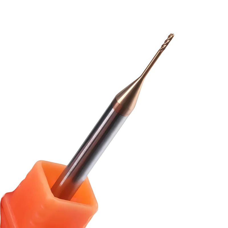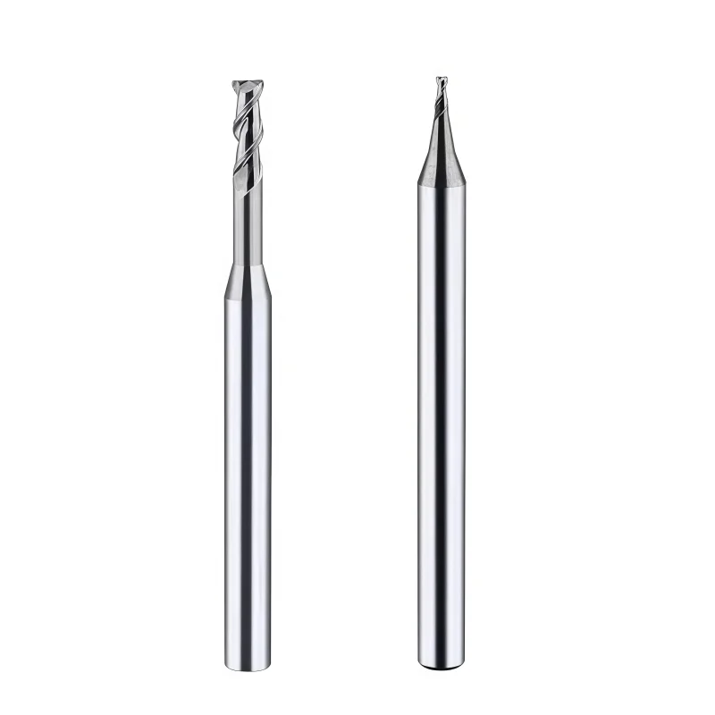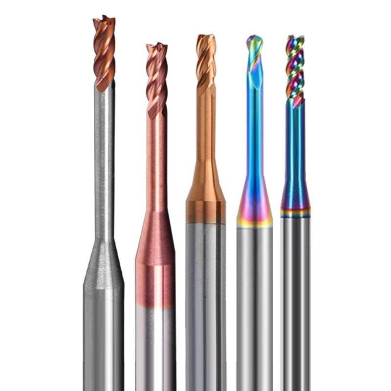
Solid Carbide Long-Neck End Mill Series for Deep-Groove and Deep-Cavity Machining
Solid carbide long-neck end mills designed for deep-groove, deep-cavity and extended-reach milling. Square-end, ball-nose and corner-radius profiles are available with application-matched geometry for steel, stainless steel, hardened steel, aluminum and selected non-ferrous materials.
⚙️ Configurations de produits
*End Profiles: Square End / Ball Nose / Corner Radius
*Flute Options: 2 Flutes / 4 Flutes
*Carbide Series: HRC45 / HRC55 / HRC60 / HRC65
*Cutting Diameter: Ø0.2–Ø20 mm reference range
*Overall Length: 50–200 mm or customized
*Helix Options: 30° / 35° / 45°
*Coating Options: Uncoated / TiN / TiAlN / AlTiN / TiSiN / AlTiSiN / DLC
*OEM Services: Custom laser marking, labels, protective tubes and private-label packaging
Une qualité constante
Une géométrie constante d'une commande à l'autre.
Commandes flexibles
Petits lots et formats variés disponibles.
Assistance OEM
Marquage, étiquettes et emballages personnalisés.
Modèles standard et sur mesure
Dimensions standard et configurations sur mesure.
Long-Neck End Mills Overview
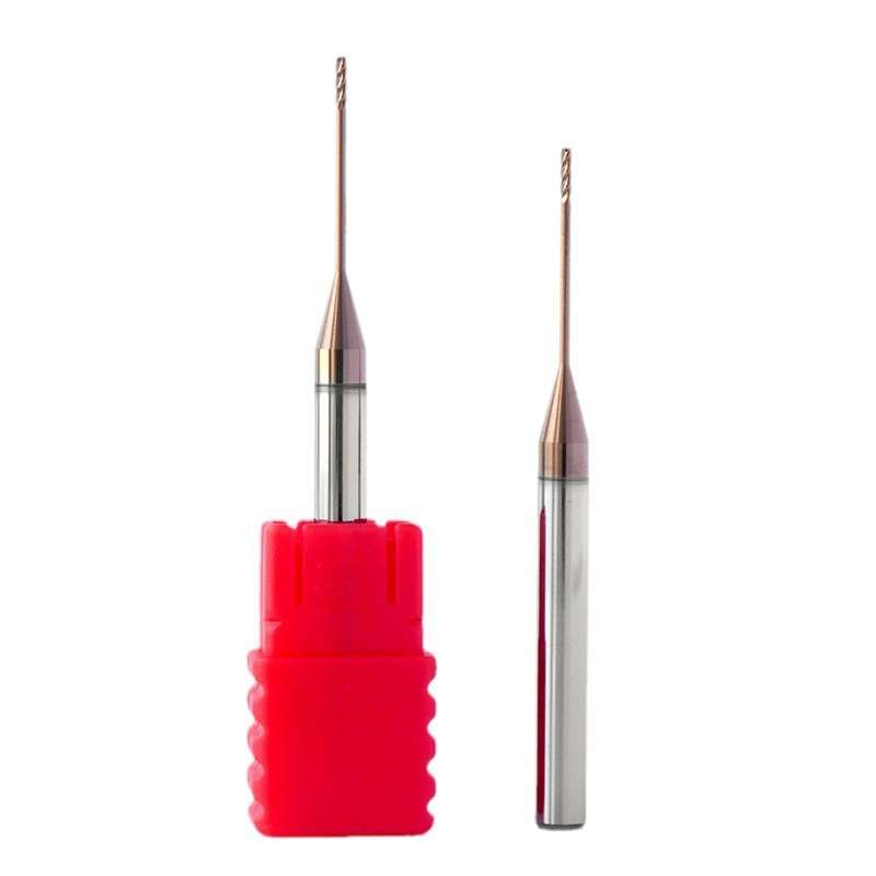
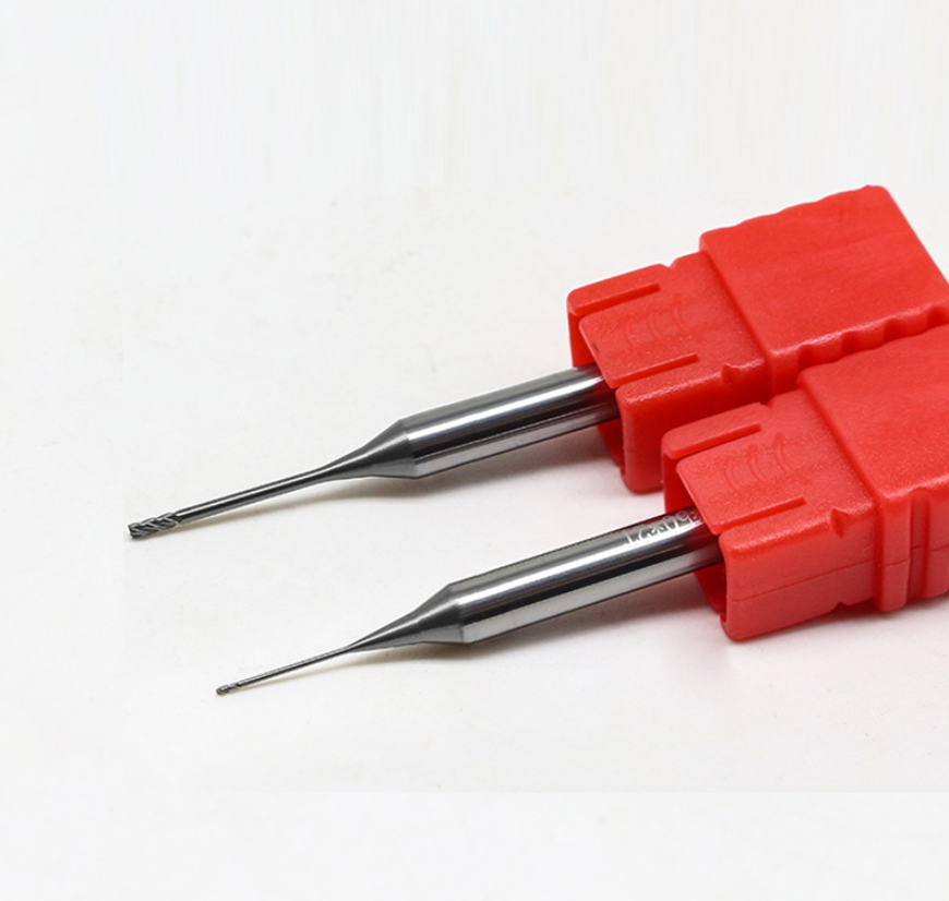
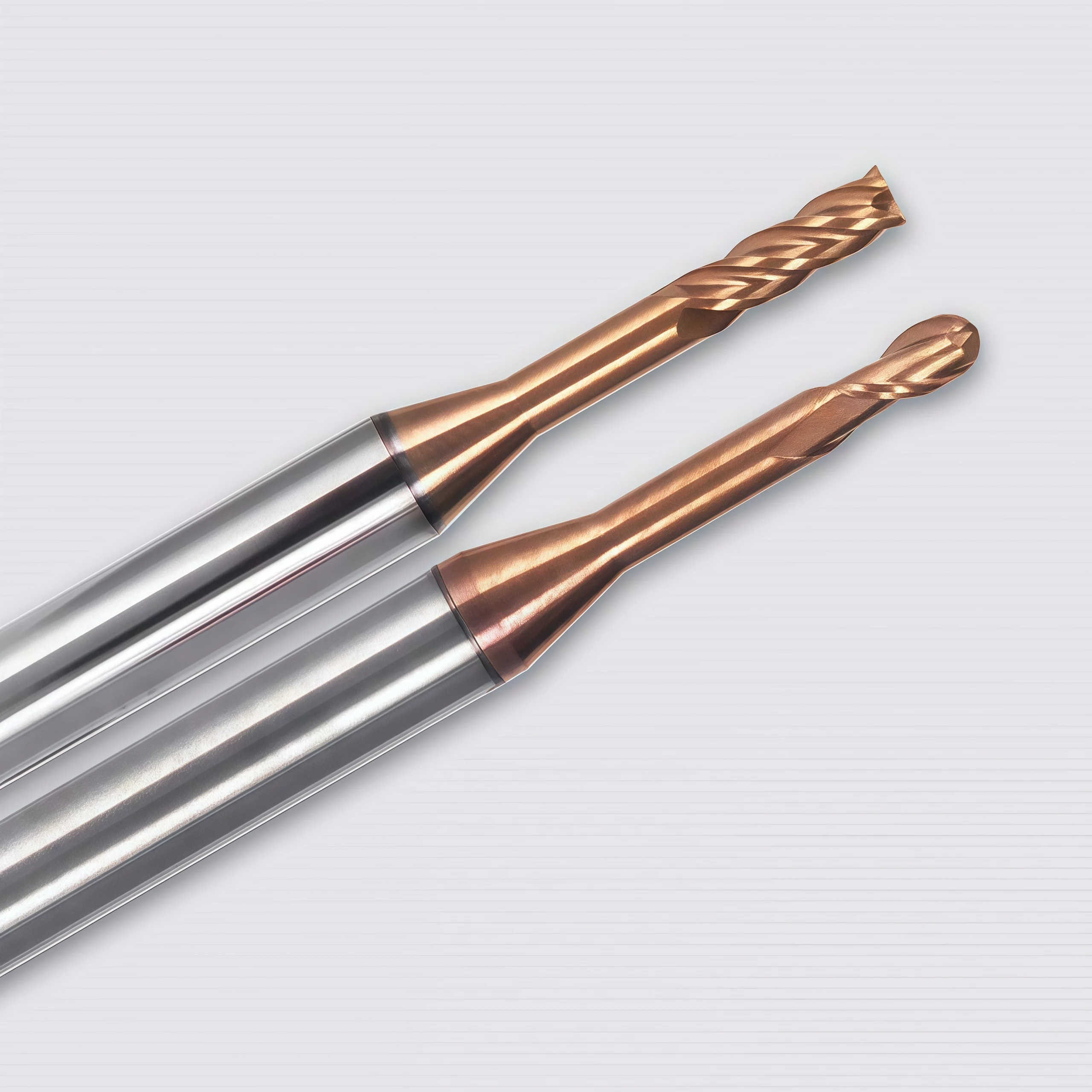
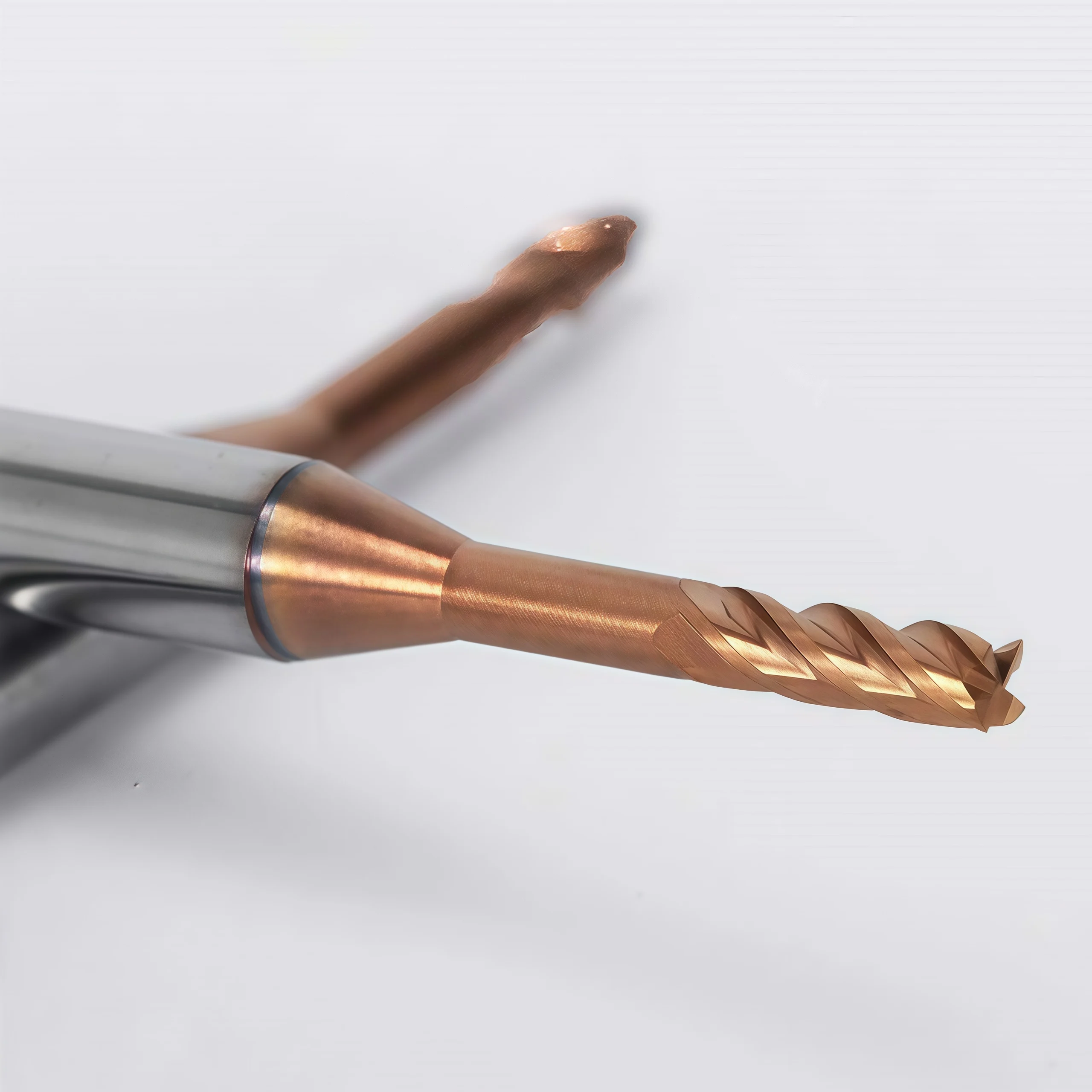
This solid carbide long-neck end mill series is designed for machining deep grooves, narrow slots, recessed features and hard-to-reach surfaces where a standard-length cutter cannot provide sufficient clearance. The reduced-neck construction extends machining reach while limiting contact between the tool body and workpiece wall. Square-end, ball-nose, corner-radius and micro-diameter configurations are available with 2-flute or 4-flute geometry. Different carbide grades, coatings, cutting diameters, neck lengths and overall lengths can be selected for steel, stainless steel, mold steel, hardened steel and other application-specific materials.
Long-Neck / Reduced-Neck
Square / Ball Nose / Corner Radius
2 Flutes / 4 Flutes
Deep Grooves & Deep Cavities
Key Features and Machining Benefits
Extended Machining Reach
The long-neck construction provides clearance for deep slots, recessed walls, narrow cavities and difficult-to-access machining areas.
Reduced-Neck Clearance
A controlled neck diameter helps reduce interference between the tool body and workpiece while maintaining the required reach.
Multiple End Profiles
Square-end, ball-nose and corner-radius geometries support deep-slot milling, 3D contouring, profiling and cavity finishing.
Flexible Series Configuration
Micro diameters, extended neck lengths, different carbide grades, 2/4-flute designs and application-specific coatings are available.
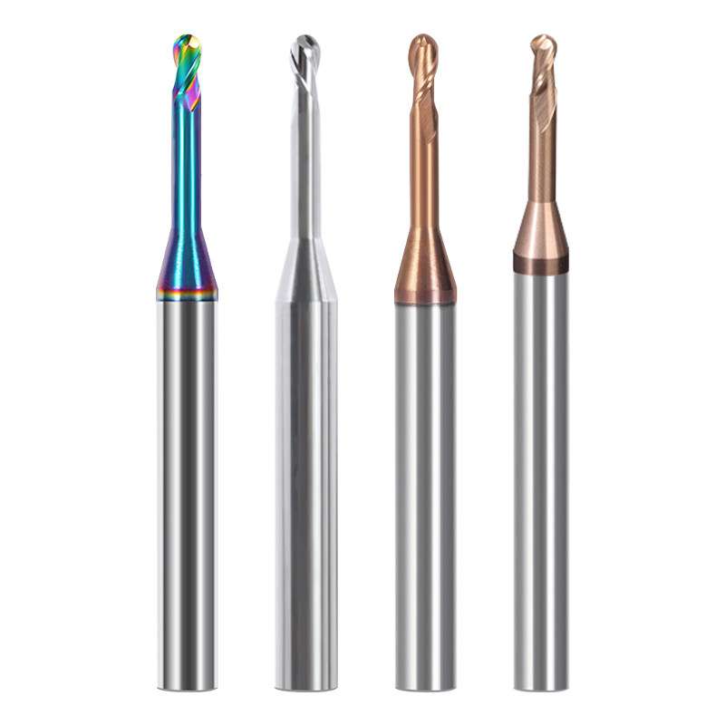
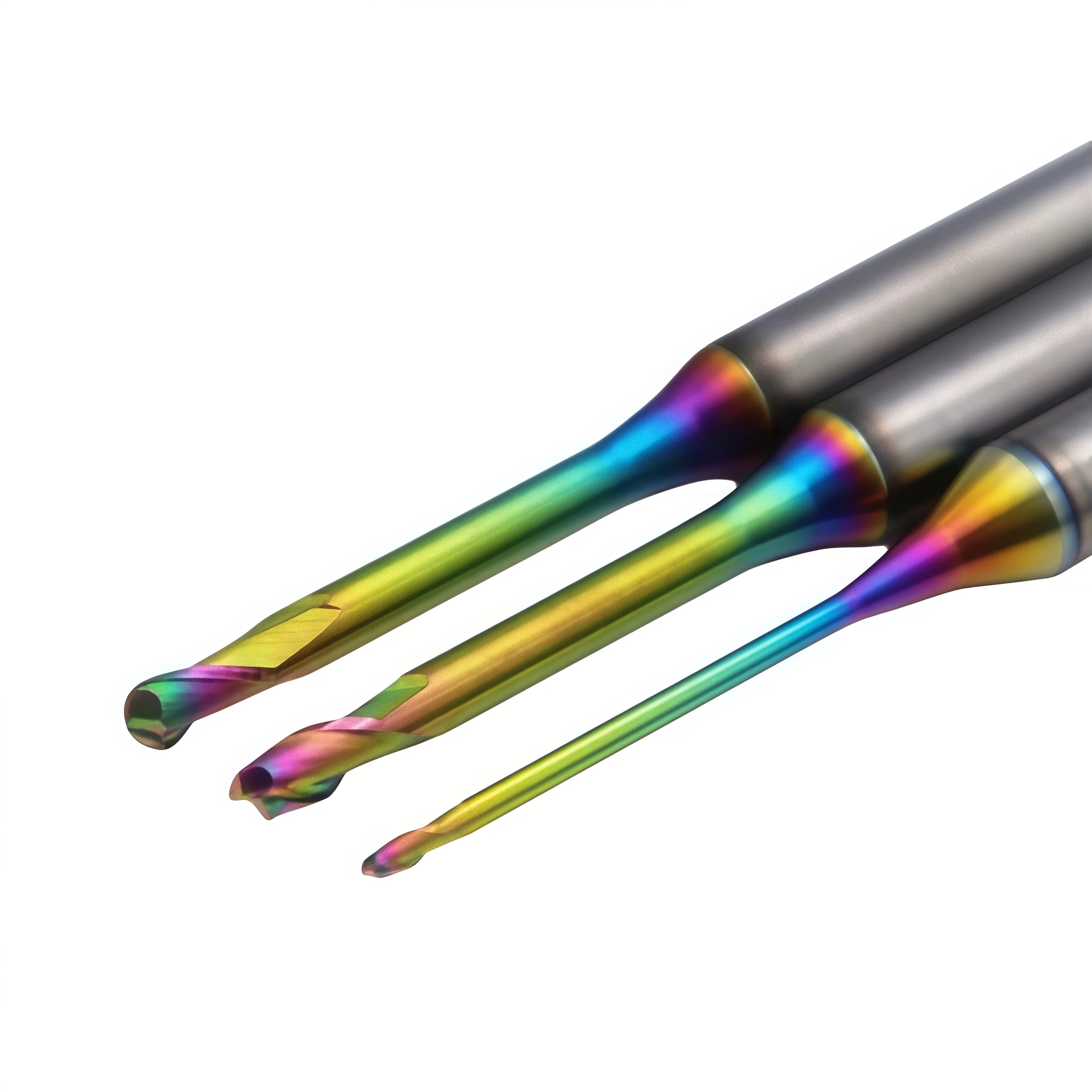
Long-Neck End Mill Series
Available configurations can be selected according to the required cutting profile, machining depth, workpiece material and surface-finish requirements.

Machining Applications
- Deep-groove and narrow-slot milling
- Deep-cavity and recessed-feature machining
- Mold-core, mold-cavity and electrode machining
- Vertical-wall profiling and corner finishing
- 3D contouring with long-neck ball-nose end mills
- Small-feature and micro-diameter precision milling
P Carbon Steel
P Alloy Steel
M Stainless Steel
H Mold & Hardened Steel
N Aluminum & Non-Ferrous
Long-Neck End Mill Technical Specifications
The series includes square-end, ball-nose, corner-radius and micro-diameter long-neck tools. The cutting diameter, neck diameter, effective reach, flute length, shank diameter and overall length should be selected as a complete configuration to control clearance, rigidity and tool deflection during deep-groove and deep-cavity machining.
| PARAMÈTRE | SERIES CONFIGURATION |
|---|---|
| Type d'outil | Solid carbide long-neck and reduced-neck end mill series for deep-groove, recessed-feature and deep-cavity machining |
| End Profiles | Square end, ball nose, corner radius and micro-diameter configurations |
| Carbide Substrate | Micro-grain or ultra-fine-grain solid carbide selected according to tool diameter, machining reach, material hardness and resistance to chipping |
| Nombre de flûtes | 2-flute and 4-flute configurations selected according to chip evacuation, tool rigidity and finishing requirements |
| Cutting Diameter | Reference range Ø0.2–Ø20 mm; micro, intermediate and drawing-defined non-standard diameters can be reviewed |
| Neck & Reach | Reduced-neck diameter and effective reach configured according to cavity depth, wall clearance and permissible tool deflection |
| Longueur totale | Reference overall lengths from 50–200 mm, with extended and drawing-defined lengths available after technical review |
| Angle de l'hélice | 30°, 35° or 45° reference geometries selected according to workpiece material, flute count and machining operation |
| Options de revêtement | AlTiN, TiAlN, TiSiN, AlTiSiN, TiN or application-specific coating |
| Hardness Series | HRC45, HRC55, HRC60 and HRC65 series available according to the workpiece material and hardness |
| Tolérance dimensionnelle | Reference tolerance up to ±0.01 mm; critical diameter, radius, reach and runout requirements are confirmed by drawing |
| Compatibilité des machines | CNC machining centers, precision milling machines and suitable high-speed machining equipment |
Dimensional Reference
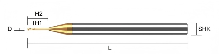
Standard Reference Sizes
The following dimensions are retained from the original product range as standard reference configurations. Ball-nose, corner-radius, micro-diameter and reduced-neck versions should be confirmed according to their individual drawings.
| CARACTÉRISTIQUES TECHNIQUES | D (mm) | L1 (mm) | d (mm) | L (mm) |
|---|---|---|---|---|
| D1–D4 × L1 × d4 × 50L | 1–4 | 3 / 6 / 9 / 12 | 4 | 50 |
| D4 × 16 × d4 × 75L | 4 | 16 | 4 | 75 |
| D4 × 20 × d4 × 100L | 4 | 20 | 4 | 100 |
| D6 × 15 × d6 × 50L | 6 | 15 | 6 | 50 |
| D6 × 24 × d6 × 75L | 6 | 24 | 6 | 75 |
| D6 × 30 × d6 × 100L | 6 | 30 | 6 | 100 |
| D8 × 20 × d8 × 60L | 8 | 20 | 8 | 60 |
| D8 × 25 × d8 × 75L | 8 | 25 | 8 | 75 |
| D8 × 35 × d8 × 100L | 8 | 35 | 8 | 100 |
| D10 × 25 × d10 × 75L | 10 | 25 | 10 | 75 |
| D10 × 40 × d10 × 100L | 10 | 40 | 10 | 100 |
| D12 × 35 × d12 × 75L | 12 | 35 | 12 | 75 |
| D12 × 45 × d12 × 100L | 12 | 45 | 12 | 100 |
| D14 × 45 × d14 × 100L | 14 | 45 | 14 | 100 |
| D16 × 45 × d16 × 100L | 16 | 45 | 16 | 100 |
| D18 × 45 × d18 × 100L | 18 | 45 | 18 | 100 |
| D20 × 45 × d20 × 100L | 20 | 45 | 20 | 100 |
Carbide Grade Reference
| GRADE | GRAIN SIZE (μm) | CO (%) | FLEXURAL STRENGTH (N/mm²) |
|---|---|---|---|
| HRC45 | 0.8 | 10 | 3320 |
| HRC55 | 0.6 | 10 | 4000 |
| HRC60 | 0.5 | 12 | 4300 |
| HRC65 | 0.4 | 12 | 4300 |
Coating Performance Reference
| COATING | COLOR | HARDNESS (HV) | THICKNESS (μm) | OXIDATION TEMP. (°C) | FRICTION COEFFICIENT |
|---|---|---|---|---|---|
| AlTiN | Noir | 3300 | 2.5-3 | 900 | 0.3 |
| TiAlN | Violet | 2800 | 2.5-3 | 900 | 0.3 |
| TiSiN | Bronze | 3600 | 3 | 1000 | 0.45 |
| AlTiSiN | Bleu | 4000 | 4 | 1200 | 0.4 |
| TiN | L'or | 2500 | 2.5-3 | 600 | 0.4 |
Solid Carbide Long-Neck End Mill Customization
Cutting diameter, end profile, flute length, neck diameter, effective reach, shank diameter, overall length, flute count, carbide grade and coating can be configured for deep-groove and deep-cavity machining. Square-end, ball-nose, corner-radius and micro-diameter long-neck tools are available with 2-flute or 4-flute geometry. Standard reference configurations and drawing-defined non-standard tools can be reviewed according to the workpiece material, cavity depth, wall clearance, tool overhang, machining operation and required surface quality.
| PARAMÈTRE | CAPACITÉS DE FABRICATION |
|---|---|
| End Profile | Square-end, ball-nose and corner-radius profiles are available for deep-slot milling, recessed-feature machining, profiling, 3D contouring and cavity finishing |
| Cutting Diameter | Reference range from Ø0.2–Ø20 mm, with micro, intermediate and drawing-defined non-standard cutting diameters available for technical review |
| Nombre de flûtes | 2-flute configurations for greater chip space and small-diameter machining, or 4-flute configurations for increased core strength, stable profiling and finishing |
| Longueur de la cannelure | Short, standard or drawing-defined flute lengths configured according to the required axial cutting depth and end-profile geometry |
| Neck Diameter | Reduced-neck diameter can be configured to provide workpiece-wall clearance while maintaining the greatest practical tool rigidity |
| Effective Reach | Standard and extended effective-reach configurations can be manufactured according to the groove depth, cavity depth, recessed feature and required wall clearance |
| Configuration de la tige | Precision cylindrical shank with standard or drawing-defined shank diameter, clamping length and neck-to-shank transition |
| Longueur totale | Reference overall lengths from 50–200 mm, with non-standard extended-length tools manufactured according to the required machining reach |
| Angle de l'hélice | 30°, 35° or 45° reference helix options selected according to the workpiece material, flute count, chip formation and machining operation |
| Cutting-Edge Geometry | Rake angle, relief geometry, end-face grinding, gash geometry and edge preparation can be matched to the workpiece material, hardness and cutting load |
| Carbide Grade | Micro-grain or ultra-fine-grain solid carbide selected according to the cutting diameter, effective reach, workpiece hardness and required balance between wear resistance and toughness |
| Hardness Series | HRC45, HRC55, HRC60 and HRC65 tool series can be configured according to the workpiece material and hardness range |
| Choix du revêtement | TiAlN, AlTiN, TiSiN or AlTiSiN for steel applications; polished uncoated or DLC configurations for aluminum and selected non-ferrous materials |
| Milling Application | Geometry can be configured for deep-groove milling, narrow slots, recessed features, deep cavities, vertical-wall profiling, corner finishing and 3D contour machining |
| Matériaux des pièces à usiner | Application-specific configurations are available for carbon steel, alloy steel, mold steel, stainless steel, hardened steel, aluminum and selected non-ferrous materials |
| Tolérance dimensionnelle | Drawing-defined control of cutting diameter, flute length, neck diameter, effective reach, shank diameter, overall length, radius and tool runout |
| Fabrication pour compte de tiers (OEM) et marques de distributeur | Custom laser marking, tool codes, dimensional identification, coating presentation, product labels, protective tubes and private-label packaging are available |
Services OEM et de marque de distributeur
Des options de fabrication OEM et d'approvisionnement sous marque de distributeur sont proposées aux distributeurs industriels, aux marques d'outillage et aux clients ayant des commandes récurrentes. Le marquage laser, le contenu des étiquettes, l'emballage de protection et la finition du revêtement peuvent être personnalisés conformément au cahier des charges approuvé et aux exigences de la commande.

Gravure au laser
Les logos personnalisés, les codes d'outils, les dimensions de coupe, l'identification du revêtement et les numéros de lot peuvent être marqués en fonction de la surface disponible sur la tige.
Étiquettes et emballages personnalisés
Il est possible de consulter les tubes de protection individuels, les étiquettes des produits, les détails techniques, les tubes d'emballage colorés et les emballages sous marque de distributeur.
Conditions commerciales
La quantité minimale de commande (MOQ), l'évaluation des échantillons, les essais de dimensions personnalisées, les commandes répétées et les programmes d'approvisionnement planifiés sont confirmés en fonction de la configuration choisie.
Processus technique
Un processus de contrôle structuré est mis en œuvre afin de vérifier la conformité des fraises à bout carré standard, sur mesure et de marque propre avant leur mise en production.
Demande de renseignements
Veuillez indiquer le matériau, la dureté, l'opération de fraisage, les dimensions, les tolérances et la quantité.
Ingénierie
Vérifier la géométrie de la canule, l'angle d'hélice, la préparation des bords, le revêtement, ainsi que les paramètres ap et ae.
Commercial
Confirmez le devis, la quantité minimale de commande (MOQ), les exigences relatives aux échantillons, le calendrier de production et les conditions de livraison.
Production
Rectification CNC, usinage des faces d'extrémité, préparation des arêtes, revêtement et marquage laser.
Contrôle qualité
Vérifiez le diamètre, la longueur de la rainure, la tige, le faux-rond, la géométrie de l'extrémité carrée et les arêtes de coupe.
Qualité, contrôle et livraison
Nos fraises à bout carré en carbure monobloc font l'objet d'un contrôle comprenant la vérification des matériaux, la rectification de précision, des mesures en cours de fabrication et un contrôle final. Les dimensions clés, la géométrie du bout carré, l'état des arêtes de coupe, l'aspect du revêtement et l'identification du produit sont vérifiés conformément au cahier des charges ou au plan approuvé avant l'emballage.

Contrôle qualité en trois étapes
Des points de contrôle sont mis en place tout au long du processus de fabrication afin de garantir la cohérence dimensionnelle et de faciliter le suivi des commandes récurrentes.
Contrôle des entrées de marchandises
La qualité du substrat en carbure, les dimensions des ébauches et les informations relatives au matériau fourni sont vérifiées par rapport aux exigences de production.
Contrôle du broyage en cours de fabrication
Le diamètre de coupe, la géométrie des goujures, la longueur des goujures, le profil de l'extrémité carrée et les dimensions de la tige sont contrôlés pendant le meulage CNC.
Inspection finale des outils
Les outils finis font l'objet d'un contrôle portant sur les cotes spécifiées, le faux-rond, l'état des arêtes de coupe, l'aspect du revêtement, le marquage et l'identification sur l'emballage.
Caractéristiques clés d'inspection
Les exigences en matière d'inspection sont définies conformément au cahier des charges standard du produit ou au plan personnalisé approuvé.
| POINT D'INSPECTION | POINT FORT : LE CONTRÔLE | BASE DE CONFIRMATION |
|---|---|---|
| Diamètre de coupe (DC) | Diamètre et homogénéité dimensionnelle | Cahier des charges standard ou plan homologué |
| Longueur de la flûte (APMX) | Longueur de coupe effective | Dimensions du produit confirmées ou exigences relatives au dessin |
| Diamètre de la tige (DCON) | Dimensions de la section de serrage et état de surface | Spécifications applicables à la tige |
| Longueur totale (OAL) | Longueur totale de l'outil | Matrice aux dimensions standard ou plan homologué |
| Faux-rond radial | Concentricité entre la partie coupante et la tige | Exigence d'inspection convenue |
| Géométrie à extrémité carrée | Profil de la face d'extrémité, état des angles et forme de la coupe centrale | Configuration de l'outil sélectionnée |
| Profil cannelé et hélicoïdal | Nombre de cannelures, forme de l'hélice et régularité de l'affûtage | Configuration de fabrication approuvée |
| Techniques de découpe et de revêtement | État des bords, défauts visibles et aspect du revêtement | Exigences de production spécifiques à l'application |
| Marquage et identification | Code de l'outil, dimensions et informations sur le lot, le cas échéant | Confirmation de la commande et spécifications d'emballage |
Mesure et traçabilité des lots
Les systèmes de mesure optique, les équipements de contrôle des outils et les jauges dimensionnelles adaptées sont choisis en fonction de la caractéristique à contrôler.
Mesure optique
Vérification du profil et des cotes des éléments de découpe spécifiés.
Vérification du faux-rond
Contrôle de la concentricité sur la base des exigences convenues pour le produit.
Inspection des bords
Examen approfondi de l'état de la face d'extrémité, des angles et du tranchant.
Identification des lots
Les informations relatives à la commande, au produit et au lot sont associées lorsque cela est nécessaire pour assurer la continuité de l'approvisionnement.
Procédé d'emballage de protection
Les fraises finies sont protégées afin de limiter le contact entre les arêtes de coupe et de garantir une identification claire des produits pendant le stockage et le transport.

Emballage pour commandes en gros et exportation
Les expéditions en vrac peuvent être organisées à l'aide de cartons renforcés, d'emballages de protection, d'un chargement sur palettes ou de caisses d'exportation, en fonction de la quantité commandée, du poids de l'envoi et des exigences de transport convenues.

Coordination des livraisons
La finalisation de la production, le mode d'emballage et les modalités d'expédition sont confirmés conformément à la commande validée. Les options d'expédition (par coursier, par avion, par voie maritime ou selon les instructions du client) peuvent être examinées en fonction du volume de l'envoi et de sa destination. Le délai de livraison définitif est confirmé une fois que les spécifications du produit, la quantité et les exigences d'emballage ont été validées.
Solid Carbide Long-Neck End Mill FAQ
Find answers about long-neck geometry, available end profiles, machining applications, material selection, tool deflection, custom dimensions, samples, lead time and OEM supply.
What is a solid carbide long-neck end mill?
What is the difference between a long-neck end mill and a long-flute end mill?
Which end profiles are available in this series?
When should I select a square, ball-nose or corner-radius type?
Are 2-flute and 4-flute configurations available?
What materials can these long-neck end mills machine?
Which carbide grades and coatings are available?
How can tool deflection and chatter be reduced?
Can these tools be used for deep full-width slotting?
Can you manufacture custom long-neck dimensions?
Can I order samples before placing a bulk order?
What is the production lead time?
Do you provide OEM and private-label services?
What information should I provide for a quotation?
Téléchargements techniques
Download general product and cutting-data references for solid carbide end mill selection and machining preparation.
Vous avez besoin d'informations sur les tailles, les prix ou les options personnalisées ?
Veuillez nous indiquer le type d'outil requis, ses dimensions, les quantités, le matériau de la pièce à usiner ainsi que toute exigence spécifique à un équipementier ou toute demande sur mesure. Nous vous confirmerons les caractéristiques techniques adaptées, la disponibilité, le délai de livraison et les détails du devis.
Les croquis, les listes de dimensions et les photos de référence sont les bienvenus.