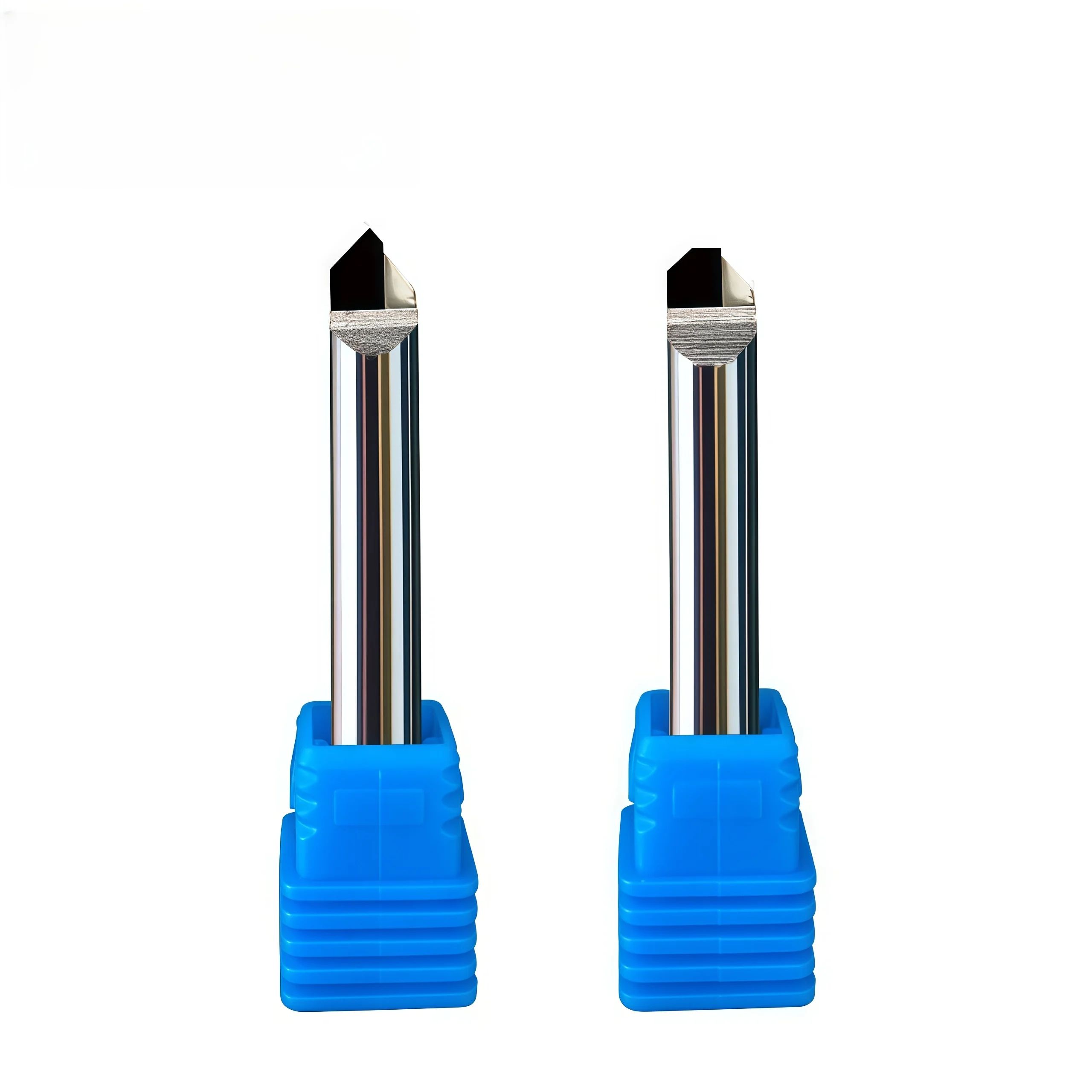
PCD Combination End Mill for Milling and Chamfering Non-Ferrous Metals
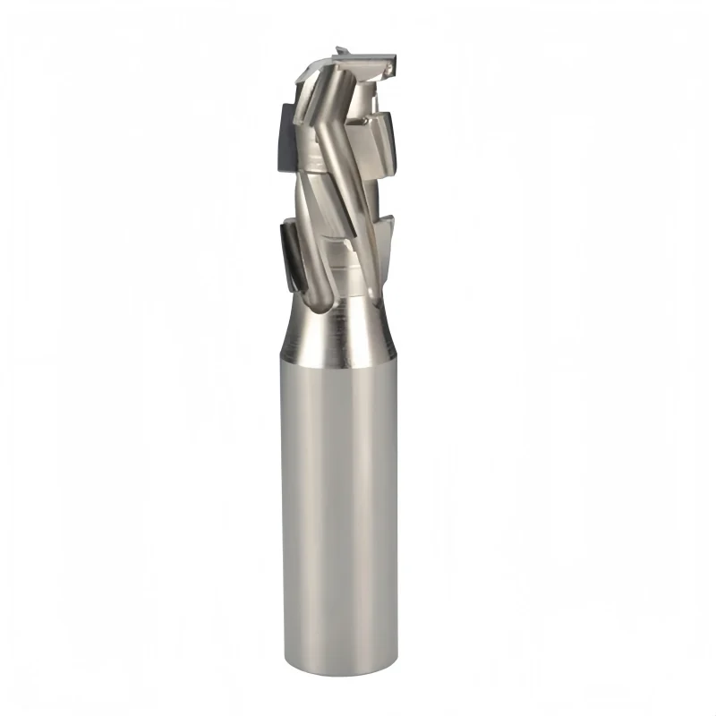
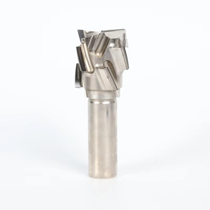
This PCD combination end mill integrates chamfering and milling for efficient machining of aluminum and other non-ferrous metals.
- ◆Combines chamfering and milling in one cutting tool
- ◆PCD cutting edge provides high wear resistance and long tool life
- ◆Produces smooth and consistent finishes on non-ferrous metals
10 PCS
1–3 Days
PCD Combination End Mill
Chamfering & Milling
PCD
Non-Ferrous Metals
Une qualité constante
Une géométrie constante d'une commande à l'autre.
Commandes flexibles
Petits lots et formats variés disponibles.
Assistance OEM
Marquage, étiquettes et emballages personnalisés.
Modèles standard et sur mesure
Dimensions standard et configurations sur mesure.
PCD Combination End Mill Overview
This PCD combination end mill is designed for precision milling and chamfering of aluminum, copper and other non-ferrous materials. The integrated cutting geometry allows multiple machining features to be completed with one tool, making it suitable for component profiles that require milling, edge chamfering and related finishing operations in a single setup. Polycrystalline diamond cutting edges provide a hard, wear-resistant cutting surface for non-ferrous machining, while custom tool geometry can be reviewed according to the required diameter, chamfer profile, machining depth and component drawing.
PCD
Combination End Mill
Milling + Chamfering
Non-Ferrous Metals
Combination Milling & Chamfering Geometry
Multi-Operation Tool Design
The cutting profile combines milling and chamfering functions so compatible component features can be machined with one tool instead of separate milling and chamfering cutters.
PCD Cutting Edge
Polycrystalline diamond cutting edges provide high hardness and wear resistance for precision machining of aluminum, copper and other compatible non-ferrous materials.
Custom Profile Integration
Milling diameter, chamfer geometry, tool length and profile dimensions can be reviewed according to the component drawing and required machining sequence.
Avantages spécifiques à l'application
Combined Operations
Integrates milling and chamfering features into one application-specific cutter.
Non-Ferrous Cutting Edge
PCD is suited to precision machining of aluminum, copper and compatible non-ferrous materials.
Precision Profile Control
Tool geometry can be matched to component dimensions and required chamfer features.
Custom Tool Supply
Non-standard diameter, length and combination profiles can be reviewed according to drawings.
Opérations d'usinage recommandées
RECOMMANDÉ
RECOMMANDÉ
CONVENABLE
CONVENABLE
Compatibilité avec les matériaux des pièces à usiner
| GROUPE DE MATÉRIAUX | APPLICATION | NIVEAU |
|---|---|---|
| N Aluminum & Aluminum Alloys | Combination milling, chamfering and profile finishing | Primaire |
| N Copper & Copper Alloys | Precision milling, chamfering and edge profiling | Primaire |
| N Brass & Bronze | Application-specific combination machining | Suitable |
| Acrylic & Engineering Plastics | Engraving, profiling and finishing where compatible with tool geometry | Application Review |
Détails du produit
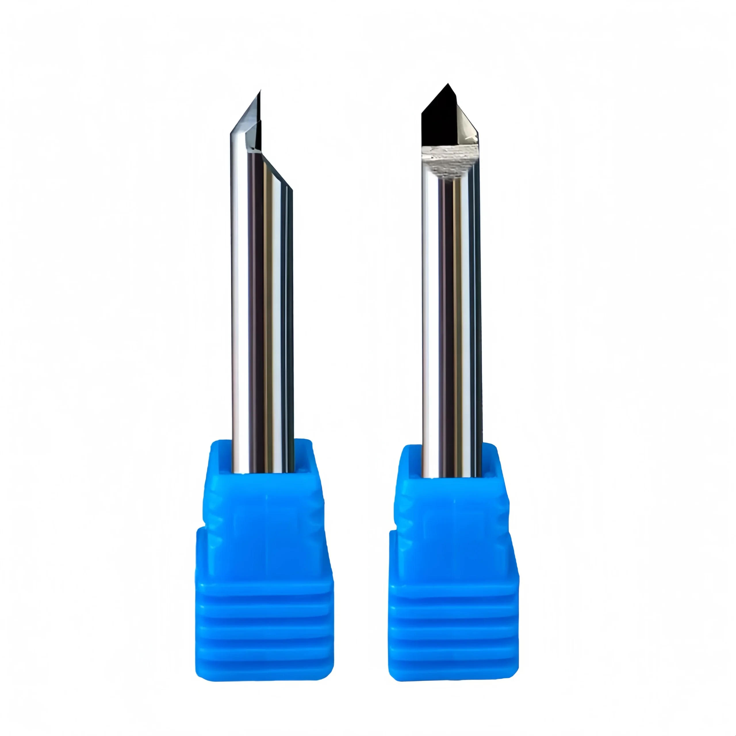
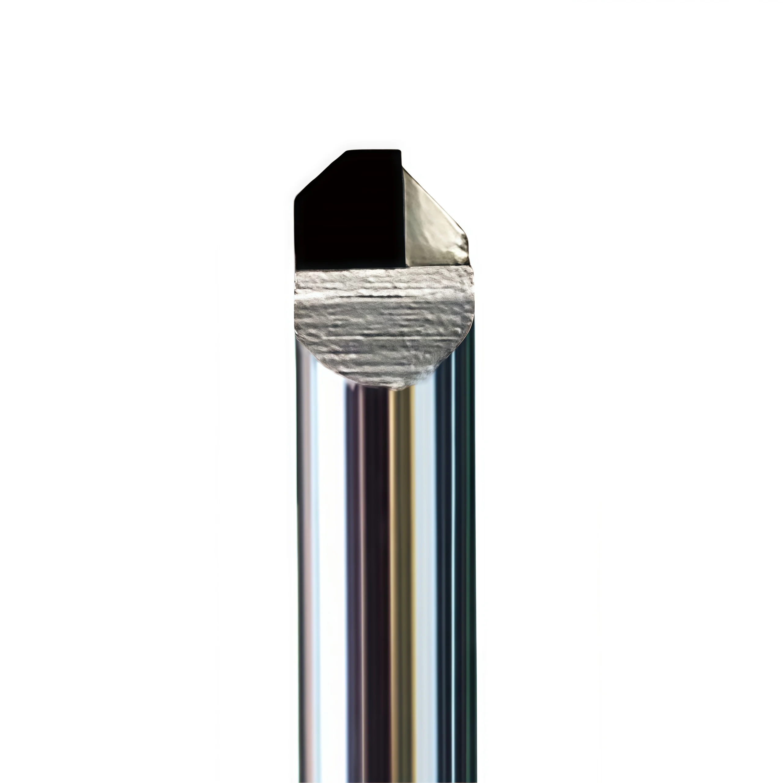
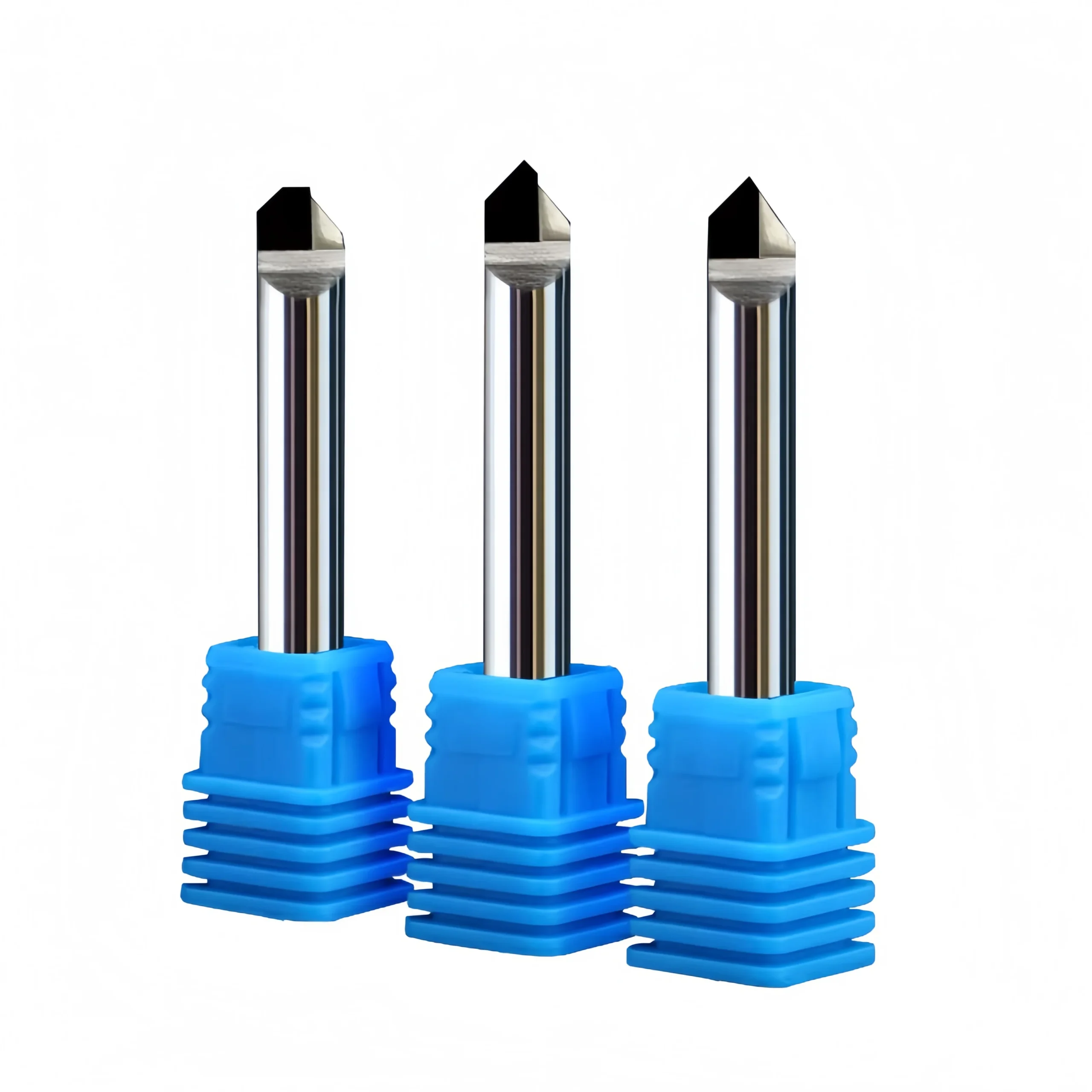
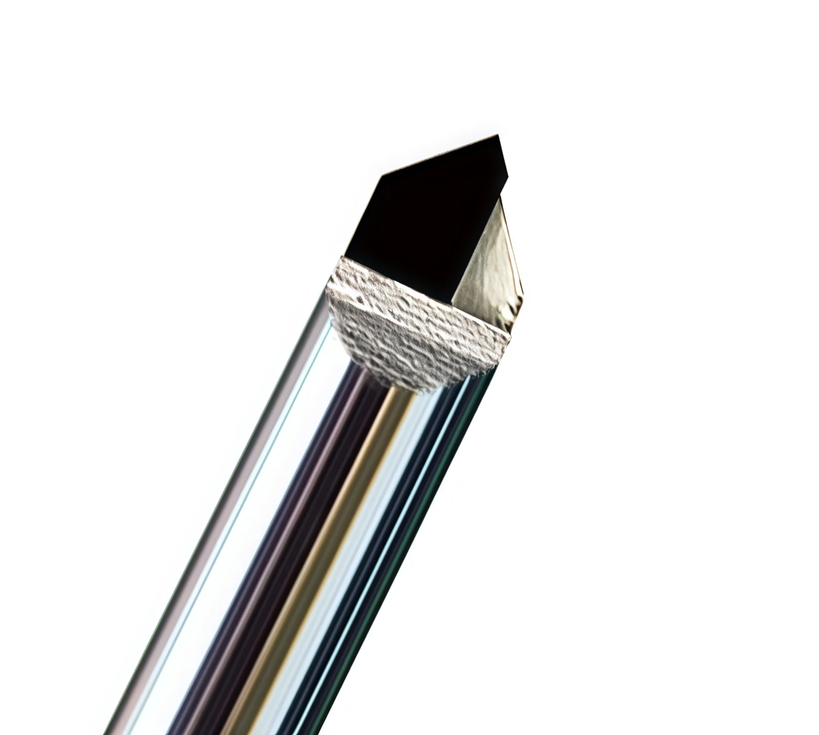
Product views showing the PCD cutting edges, combination cutting profile and custom tool geometry for non-ferrous machining.
Tool Geometry & Dimensions
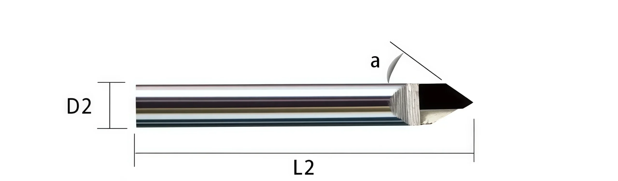
The PCD combination end mill integrates milling and chamfering features into one application-specific cutting profile. Diameter, chamfer geometry, cutting length, shank dimensions and overall length should be confirmed according to the component drawing and machining sequence. Standard sizes and custom dimensional configurations are available according to the selected tool design.
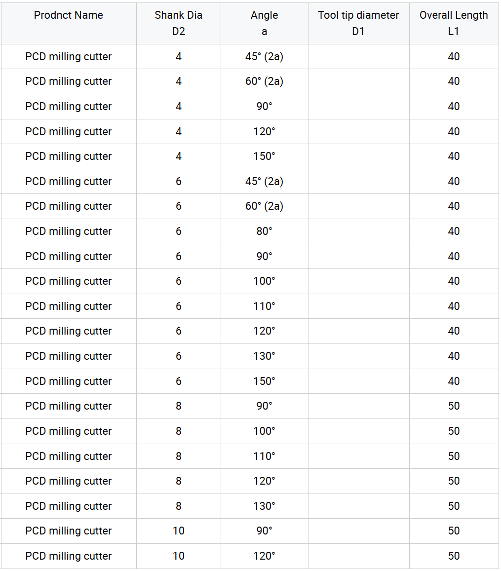
Configuration technique
| PARAMÈTRE | CONFIGURATION DE RÉFÉRENCE |
|---|---|
| Type d'outil | PCD Combination End Mill / Milling & Chamfering Cutter |
| Cutting Material | Polycrystalline Diamond (PCD) |
| Cutting Geometry | Combination milling and chamfering profile |
| Matières premières | Aluminum / Aluminum Alloys / Copper / Copper Alloys / Brass / Bronze |
| Additional Materials | Acrylic and compatible engineering plastics subject to application review |
| Machining Operations | Milling / Chamfering / Edge Profiling / Engraving / Precision Finishing |
| Diameter | Standard or custom according to selected specification and component drawing |
| Chamfer Geometry | Standard or drawing-defined angle, width and profile according to component requirements |
| Tool Length | Standard or custom cutting length, reach and overall length |
| Configuration de la tige | Standard or drawing-defined cylindrical shank according to holder requirements |
| Customization | Diameter, combination profile, chamfer geometry, cutting length, shank dimensions, overall length and flute design can be reviewed according to component drawings. |
Starting Cutting Data
The following values are reference starting ranges from the current product data. Final parameters should be adjusted according to tool diameter, PCD edge configuration, machine rigidity, workpiece grade, cutting engagement and required surface quality.
Copper & Aluminum
| PARAMÈTRE | REFERENCE RANGE |
|---|---|
| Cutting Speed Vc | 500–1200 m/min |
| Feed per Tooth fz | 0.05–0.15 mm/tooth |
| Axial Depth ap | 0.5–1.0 × D |
| Radial Step-over ae | 0.1–0.3 × D |
Acrylic & Soft Plastics
| PARAMÈTRE | REFERENCE RANGE |
|---|---|
| Cutting Speed Vc | 800–1500 m/min |
| Feed per Tooth fz | 0.05–0.12 mm/tooth |
| Axial Depth ap | 0.3–0.6 × D |
| Radial Step-over ae | 0.05–0.25 × D |
Recommandations pour l'usinage
- Toolholding: Use a rigid, low-runout CNC toolholder to maintain the accuracy of both the milling and chamfering features.
- Chip Evacuation: Air blast or minimum-quantity lubrication can be considered according to the workpiece material and machining conditions.
- Finishing Operations: Reduce feed and radial engagement where finer engraving or higher surface-finish requirements are required.
- Combination Profile: Confirm that both the milling diameter and chamfer geometry match the component before setting machining depth.
- PCD Edge Protection: Avoid impact, excessive runout and unstable tool engagement that may damage the PCD cutting edge.
PCD Combination End Mill Customization
Milling diameter, chamfer angle, chamfer width, combination profile, cutting length, shank diameter, overall length and PCD cutting-edge configuration can be customized for aluminum, copper and other non-ferrous machining applications. The cutting profile can integrate milling, chamfering and selected edge-forming features into one tool according to the component geometry and machining sequence. Non-standard combination cutters are reviewed from component drawings, existing tool drawings or physical samples to confirm feature positions, dimensional relationships and PCD edge requirements before production.
| PARAMÈTRE | CAPACITÉS DE FABRICATION |
|---|---|
| Milling Diameter | Standard-equivalent and non-standard milling diameters can be reviewed according to the component feature, machining allowance and required finished dimension. |
| Chamfer Angle | Chamfer angle can be manufactured according to the component drawing and required edge geometry. The drawing should clearly define the included angle or finished chamfer requirement. |
| Chamfer Width | Target chamfer width can be integrated into the cutter profile according to the machining depth, cutting position and component geometry. |
| Combination Profile | Milling, chamfering, step and selected edge-forming features can be combined into one cutting profile where the component geometry and machining sequence allow multi-operation machining. |
| Step Position & Geometry | Step diameter, axial position, shoulder relationship and transition geometry can be reviewed according to the component drawing when multiple features are machined in one pass or setup. |
| PCD Cutting-Edge Configuration | PCD edge arrangement, cutting-edge position and application-specific geometry can be reviewed according to the milling operation, chamfer feature, material and required surface condition. |
| Longueur de coupe | Cutting length and effective machining reach can be configured according to component depth, feature position and holder-clearance requirements. |
| Configuration de la tige | Precision cylindrical shank dimensions and clamping length can be selected according to the CNC holder and machine-spindle requirements. |
| Longueur totale | Overall length can be adjusted according to machining reach, component clearance, fixture conditions and required tool rigidity. |
| Workpiece Material | Geometry can be reviewed for aluminum and aluminum alloys, copper and copper alloys, brass, bronze and other compatible non-ferrous materials. Acrylic and selected plastics can also be reviewed separately. |
| Application d'usinage | Tool profiles can be developed for combination milling, chamfering, edge profiling, engraving and precision finishing according to the required machining sequence. |
| Profile & Dimensional Tolerance | Drawing-defined requirements can be reviewed for milling diameter, chamfer geometry, step position, cutting length, shank dimensions, overall length, profile relationship and tool runout. |
| Correspondance des outils de remplacement | Existing combination cutters can be reviewed from a detailed tool drawing or physical sample when an equivalent or replacement PCD tool is required. |
| Fabrication pour compte de tiers (OEM) et marques de distributeur | Laser marking, custom tool codes, private labels and packaging can be reviewed for distributors and OEM customers according to tool dimensions and order quantity. |
Services OEM et de marque de distributeur
Des options de fabrication OEM et d'approvisionnement sous marque de distributeur sont proposées aux distributeurs industriels, aux marques d'outillage et aux clients ayant des commandes récurrentes. Le marquage laser, le contenu des étiquettes, l'emballage de protection et la finition du revêtement peuvent être personnalisés conformément au cahier des charges approuvé et aux exigences de la commande.

Gravure au laser
Les logos personnalisés, les codes d'outils, les dimensions de coupe, l'identification du revêtement et les numéros de lot peuvent être marqués en fonction de la surface disponible sur la tige.
Étiquettes et emballages personnalisés
Il est possible de consulter les tubes de protection individuels, les étiquettes des produits, les détails techniques, les tubes d'emballage colorés et les emballages sous marque de distributeur.
Conditions commerciales
La quantité minimale de commande (MOQ), l'évaluation des échantillons, les essais de dimensions personnalisées, les commandes répétées et les programmes d'approvisionnement planifiés sont confirmés en fonction de la configuration choisie.
Processus technique
Un processus de contrôle structuré est mis en œuvre afin de vérifier la conformité des fraises à bout carré standard, sur mesure et de marque propre avant leur mise en production.
Demande de renseignements
Veuillez indiquer le matériau, la dureté, l'opération de fraisage, les dimensions, les tolérances et la quantité.
Ingénierie
Vérifier la géométrie de la canule, l'angle d'hélice, la préparation des bords, le revêtement, ainsi que les paramètres ap et ae.
Commercial
Confirmez le devis, la quantité minimale de commande (MOQ), les exigences relatives aux échantillons, le calendrier de production et les conditions de livraison.
Production
Rectification CNC, usinage des faces d'extrémité, préparation des arêtes, revêtement et marquage laser.
Contrôle qualité
Vérifiez le diamètre, la longueur de la rainure, la tige, le faux-rond, la géométrie de l'extrémité carrée et les arêtes de coupe.
Qualité, contrôle et livraison
Nos fraises à bout carré en carbure monobloc font l'objet d'un contrôle comprenant la vérification des matériaux, la rectification de précision, des mesures en cours de fabrication et un contrôle final. Les dimensions clés, la géométrie du bout carré, l'état des arêtes de coupe, l'aspect du revêtement et l'identification du produit sont vérifiés conformément au cahier des charges ou au plan approuvé avant l'emballage.

Contrôle qualité en trois étapes
Des points de contrôle sont mis en place tout au long du processus de fabrication afin de garantir la cohérence dimensionnelle et de faciliter le suivi des commandes récurrentes.
Contrôle des entrées de marchandises
La qualité du substrat en carbure, les dimensions des ébauches et les informations relatives au matériau fourni sont vérifiées par rapport aux exigences de production.
Contrôle du broyage en cours de fabrication
Le diamètre de coupe, la géométrie des goujures, la longueur des goujures, le profil de l'extrémité carrée et les dimensions de la tige sont contrôlés pendant le meulage CNC.
Inspection finale des outils
Les outils finis font l'objet d'un contrôle portant sur les cotes spécifiées, le faux-rond, l'état des arêtes de coupe, l'aspect du revêtement, le marquage et l'identification sur l'emballage.
Caractéristiques clés d'inspection
Les exigences en matière d'inspection sont définies conformément au cahier des charges standard du produit ou au plan personnalisé approuvé.
| POINT D'INSPECTION | POINT FORT : LE CONTRÔLE | BASE DE CONFIRMATION |
|---|---|---|
| Diamètre de coupe (DC) | Diamètre et homogénéité dimensionnelle | Cahier des charges standard ou plan homologué |
| Longueur de la flûte (APMX) | Longueur de coupe effective | Dimensions du produit confirmées ou exigences relatives au dessin |
| Diamètre de la tige (DCON) | Dimensions de la section de serrage et état de surface | Spécifications applicables à la tige |
| Longueur totale (OAL) | Longueur totale de l'outil | Matrice aux dimensions standard ou plan homologué |
| Faux-rond radial | Concentricité entre la partie coupante et la tige | Exigence d'inspection convenue |
| Géométrie à extrémité carrée | Profil de la face d'extrémité, état des angles et forme de la coupe centrale | Configuration de l'outil sélectionnée |
| Profil cannelé et hélicoïdal | Nombre de cannelures, forme de l'hélice et régularité de l'affûtage | Configuration de fabrication approuvée |
| Techniques de découpe et de revêtement | État des bords, défauts visibles et aspect du revêtement | Exigences de production spécifiques à l'application |
| Marquage et identification | Code de l'outil, dimensions et informations sur le lot, le cas échéant | Confirmation de la commande et spécifications d'emballage |
Mesure et traçabilité des lots
Les systèmes de mesure optique, les équipements de contrôle des outils et les jauges dimensionnelles adaptées sont choisis en fonction de la caractéristique à contrôler.
Mesure optique
Vérification du profil et des cotes des éléments de découpe spécifiés.
Vérification du faux-rond
Contrôle de la concentricité sur la base des exigences convenues pour le produit.
Inspection des bords
Examen approfondi de l'état de la face d'extrémité, des angles et du tranchant.
Identification des lots
Les informations relatives à la commande, au produit et au lot sont associées lorsque cela est nécessaire pour assurer la continuité de l'approvisionnement.
Procédé d'emballage de protection
Les fraises finies sont protégées afin de limiter le contact entre les arêtes de coupe et de garantir une identification claire des produits pendant le stockage et le transport.

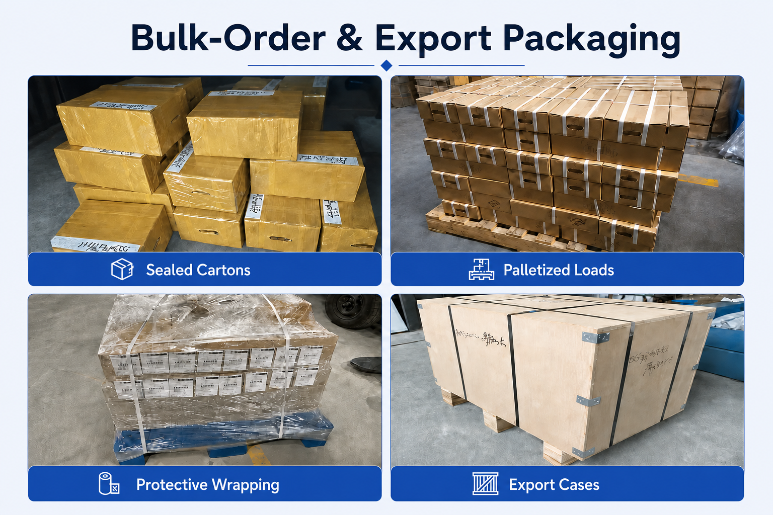
Emballage pour commandes en gros et exportation
Les expéditions en vrac peuvent être organisées à l'aide de cartons renforcés, d'emballages de protection, d'un chargement sur palettes ou de caisses d'exportation, en fonction de la quantité commandée, du poids de l'envoi et des exigences de transport convenues.
Coordination des livraisons
La finalisation de la production, le mode d'emballage et les modalités d'expédition sont confirmés conformément à la commande validée. Les options d'expédition (par coursier, par avion, par voie maritime ou selon les instructions du client) peuvent être examinées en fonction du volume de l'envoi et de sa destination. Le délai de livraison définitif est confirmé une fois que les spécifications du produit, la quantité et les exigences d'emballage ont été validées.
FAQ sur les produits et leurs applications
Common questions about the PCD Combination End Mill for milling, chamfering and precision profile machining of aluminum, copper and other non-ferrous materials.
What operations can this PCD combination end mill perform?
What is the advantage of combining milling and chamfering in one tool?
Which materials is this PCD cutter suitable for?
Why is PCD used for non-ferrous machining?
Can the chamfer angle and milling profile be customized?
Can this tool be used for steel machining?
What should be considered when setting cutting parameters?
FAQ sur les commandes et la personnalisation
Ordering information for distributors, tooling suppliers and OEM customers requiring standard or custom PCD combination milling and chamfering cutters.
Are standard and custom sizes available?
Can you manufacture a cutter from my component drawing?
Can the PCD edge configuration be customized?
Proposez-vous le marquage OEM et le conditionnement sous marque de distributeur ?
Quel est le délai de livraison habituel ?
Quelles informations dois-je fournir pour obtenir un devis ?
Téléchargements techniques
Reference documents for solid carbide and special milling tool selection and machining-data review.
Cutting Tool Catalog
Review milling cutters and related custom cutting tool series.
Speeds & Feeds Guide
Access reference machining information for application and cutting-data review.
Vous avez besoin d'informations sur les tailles, les prix ou les options personnalisées ?
Veuillez nous indiquer le type d'outil requis, ses dimensions, les quantités, le matériau de la pièce à usiner ainsi que toute exigence spécifique à un équipementier ou toute demande sur mesure. Nous vous confirmerons les caractéristiques techniques adaptées, la disponibilité, le délai de livraison et les détails du devis.
Les croquis, les listes de dimensions et les photos de référence sont les bienvenus.