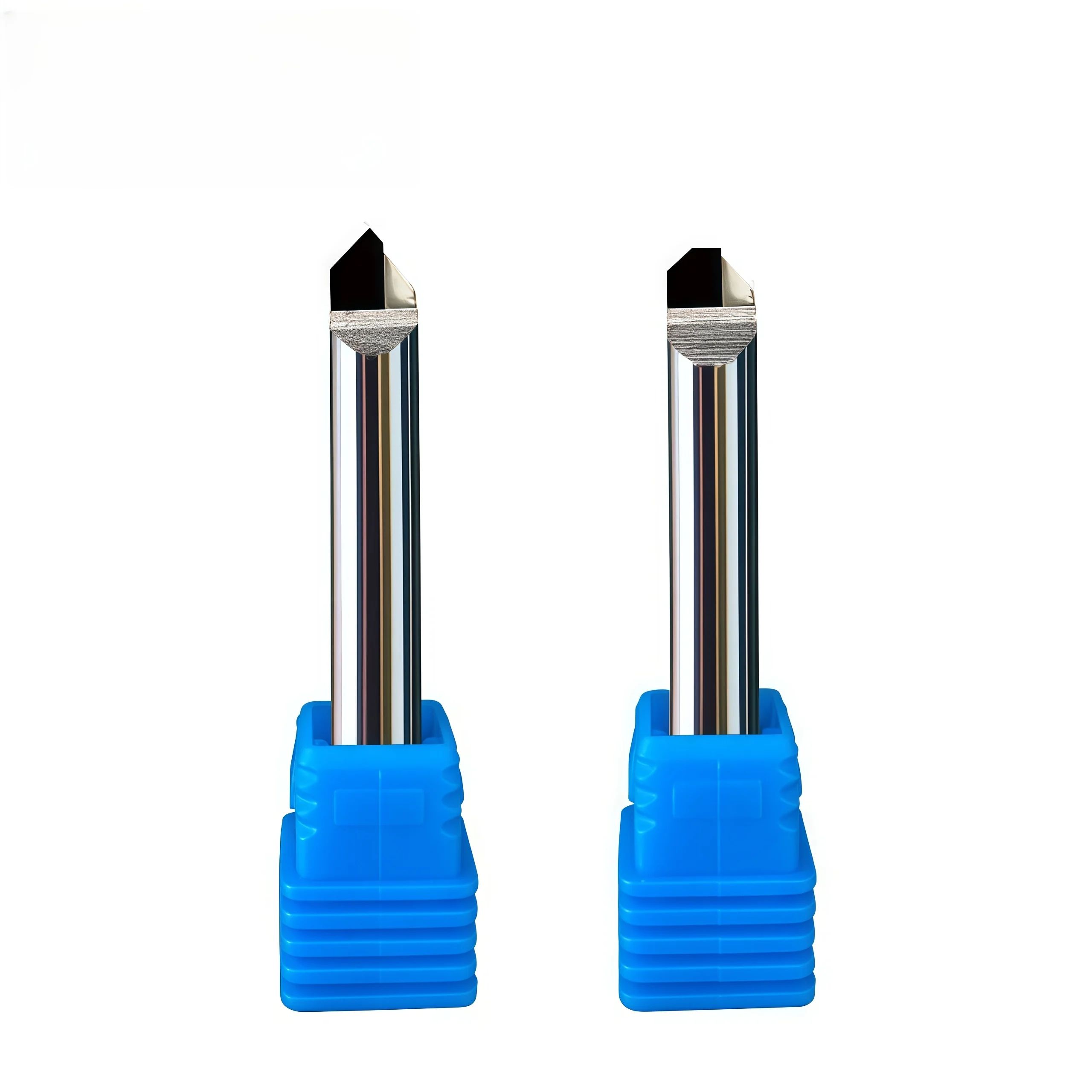
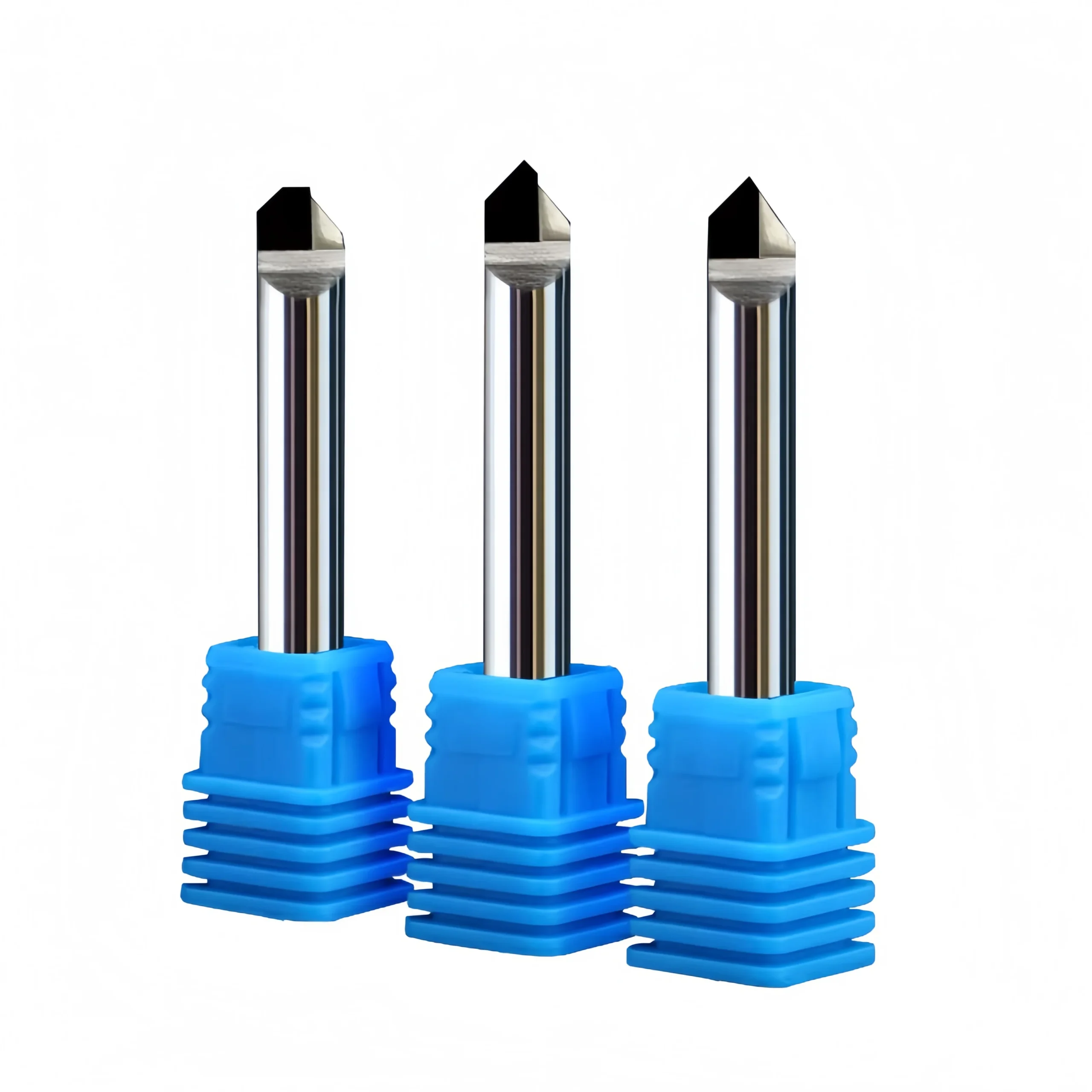
PCD Combination End Mill for Milling and Chamfering Non-Ferrous Metals
This PCD combination end mill integrates chamfering and milling for efficient machining of aluminum and other non-ferrous metals.
- ◆Combines chamfering and milling in one cutting tool
- ◆PCD cutting edge provides high wear resistance and long tool life
- ◆Produces smooth and consistent finishes on non-ferrous metals
10 PCS
1–3 Days
PCD Combination End Mill
Chamfering & Milling
PCD
Non-Ferrous Metals
Consistent Quality
Consistent geometry across repeat orders.
Đơn hàng linh hoạt
Small batches and mixed sizes available.
OEM Support
Custom marking, labels and packaging.
Tiêu chuẩn & Theo yêu cầu
Standard sizes and custom configurations.
PCD Combination End Mill Overview
This PCD combination end mill is designed for precision milling and chamfering of aluminum, copper and other non-ferrous materials. The integrated cutting geometry allows multiple machining features to be completed with one tool, making it suitable for component profiles that require milling, edge chamfering and related finishing operations in a single setup. Polycrystalline diamond cutting edges provide a hard, wear-resistant cutting surface for non-ferrous machining, while custom tool geometry can be reviewed according to the required diameter, chamfer profile, machining depth and component drawing.
PCD
Combination End Mill
Milling + Chamfering
Non-Ferrous Metals
Combination Milling & Chamfering Geometry
Multi-Operation Tool Design
The cutting profile combines milling and chamfering functions so compatible component features can be machined with one tool instead of separate milling and chamfering cutters.
PCD Cutting Edge
Polycrystalline diamond cutting edges provide high hardness and wear resistance for precision machining of aluminum, copper and other compatible non-ferrous materials.
Custom Profile Integration
Milling diameter, chamfer geometry, tool length and profile dimensions can be reviewed according to the component drawing and required machining sequence.
Application-Specific Advantages
Combined Operations
Integrates milling and chamfering features into one application-specific cutter.
Non-Ferrous Cutting Edge
PCD is suited to precision machining of aluminum, copper and compatible non-ferrous materials.
Precision Profile Control
Tool geometry can be matched to component dimensions and required chamfer features.
Custom Tool Supply
Non-standard diameter, length and combination profiles can be reviewed according to drawings.
Recommended Machining Operations
RECOMMENDED
RECOMMENDED
SUITABLE
SUITABLE
Workpiece Material Compatibility
| MATERIAL GROUP | APPLICATION | LEVEL |
|---|---|---|
| N Aluminum & Aluminum Alloys | Combination milling, chamfering and profile finishing | Primary |
| N Copper & Copper Alloys | Precision milling, chamfering and edge profiling | Primary |
| N Brass & Bronze | Application-specific combination machining | Suitable |
| Acrylic & Engineering Plastics | Engraving, profiling and finishing where compatible with tool geometry | Application Review |
Product Details
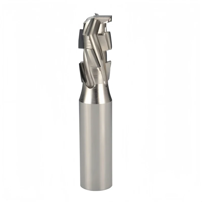
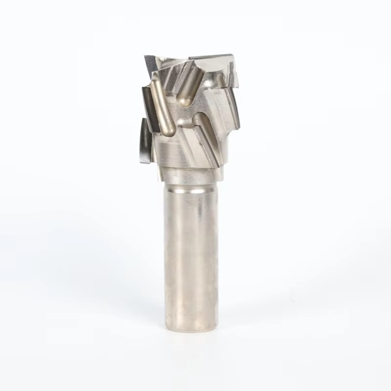
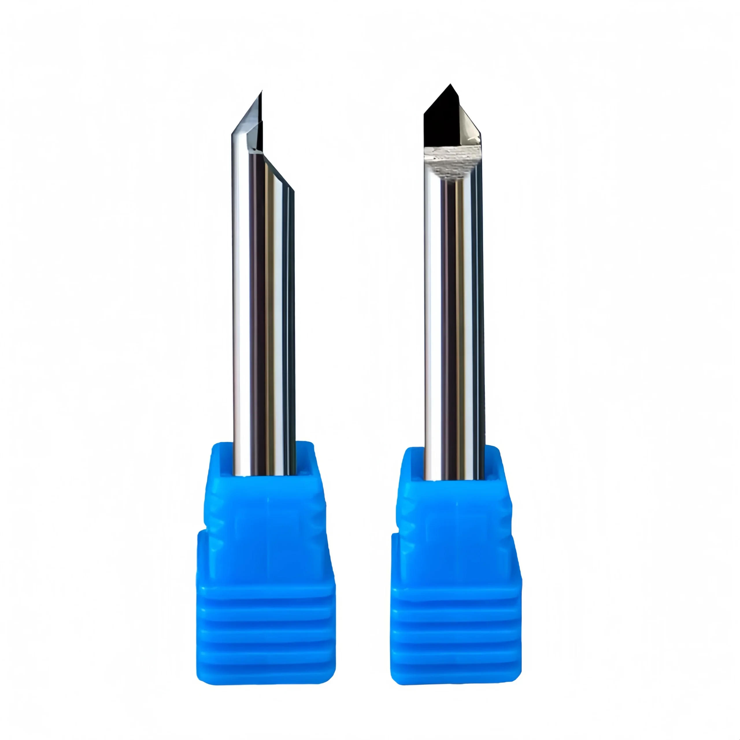
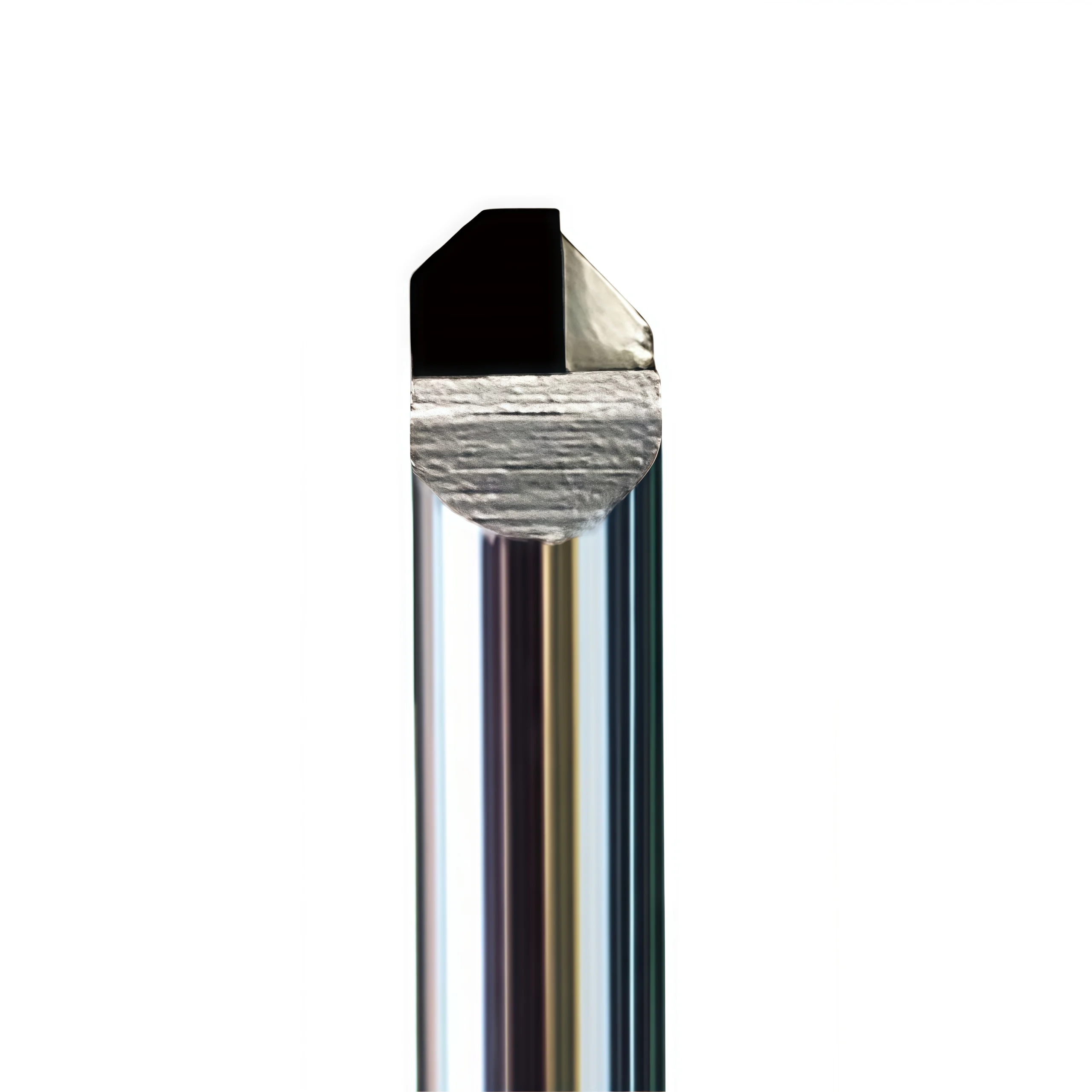
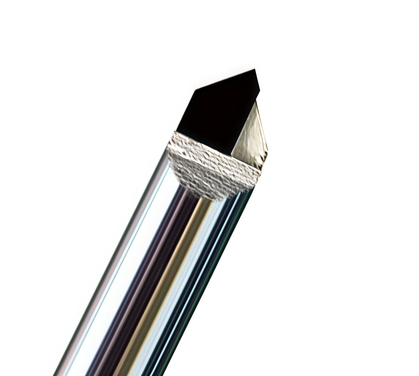
Product views showing the PCD cutting edges, combination cutting profile and custom tool geometry for non-ferrous machining.
Tool Geometry & Dimensions
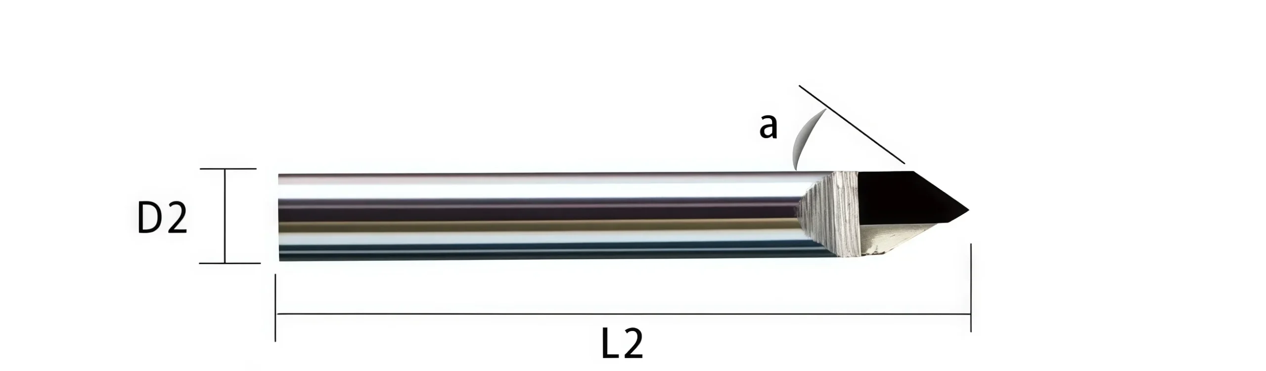
The PCD combination end mill integrates milling and chamfering features into one application-specific cutting profile. Diameter, chamfer geometry, cutting length, shank dimensions and overall length should be confirmed according to the component drawing and machining sequence. Standard sizes and custom dimensional configurations are available according to the selected tool design.
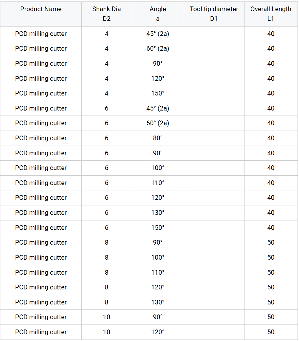
Technical Configuration
| PARAMETER | REFERENCE CONFIGURATION |
|---|---|
| Tool Type | PCD Combination End Mill / Milling & Chamfering Cutter |
| Cutting Material | Polycrystalline Diamond (PCD) |
| Cutting Geometry | Combination milling and chamfering profile |
| Primary Materials | Aluminum / Aluminum Alloys / Copper / Copper Alloys / Brass / Bronze |
| Additional Materials | Acrylic and compatible engineering plastics subject to application review |
| Machining Operations | Milling / Chamfering / Edge Profiling / Engraving / Precision Finishing |
| Diameter | Standard or custom according to selected specification and component drawing |
| Chamfer Geometry | Standard or drawing-defined angle, width and profile according to component requirements |
| Tool Length | Standard or custom cutting length, reach and overall length |
| Shank Configuration | Standard or drawing-defined cylindrical shank according to holder requirements |
| Customization | Diameter, combination profile, chamfer geometry, cutting length, shank dimensions, overall length and flute design can be reviewed according to component drawings. |
Starting Cutting Data
The following values are reference starting ranges from the current product data. Final parameters should be adjusted according to tool diameter, PCD edge configuration, machine rigidity, workpiece grade, cutting engagement and required surface quality.
Copper & Aluminum
| PARAMETER | REFERENCE RANGE |
|---|---|
| Cutting Speed Vc | 500–1200 m/min |
| Feed per Tooth fz | 0.05–0.15 mm/tooth |
| Axial Depth ap | 0.5–1.0 × D |
| Radial Step-over ae | 0.1–0.3 × D |
Acrylic & Soft Plastics
| PARAMETER | REFERENCE RANGE |
|---|---|
| Cutting Speed Vc | 800–1500 m/min |
| Feed per Tooth fz | 0.05–0.12 mm/tooth |
| Axial Depth ap | 0.3–0.6 × D |
| Radial Step-over ae | 0.05–0.25 × D |
Machining Recommendations
- Toolholding: Use a rigid, low-runout CNC toolholder to maintain the accuracy of both the milling and chamfering features.
- Chip Evacuation: Air blast or minimum-quantity lubrication can be considered according to the workpiece material and machining conditions.
- Finishing Operations: Reduce feed and radial engagement where finer engraving or higher surface-finish requirements are required.
- Combination Profile: Confirm that both the milling diameter and chamfer geometry match the component before setting machining depth.
- PCD Edge Protection: Avoid impact, excessive runout and unstable tool engagement that may damage the PCD cutting edge.
PCD Combination End Mill Customization
Milling diameter, chamfer angle, chamfer width, combination profile, cutting length, shank diameter, overall length and PCD cutting-edge configuration can be customized for aluminum, copper and other non-ferrous machining applications. The cutting profile can integrate milling, chamfering and selected edge-forming features into one tool according to the component geometry and machining sequence. Non-standard combination cutters are reviewed from component drawings, existing tool drawings or physical samples to confirm feature positions, dimensional relationships and PCD edge requirements before production.
| PARAMETER | MANUFACTURING CAPABILITIES |
|---|---|
| Milling Diameter | Standard-equivalent and non-standard milling diameters can be reviewed according to the component feature, machining allowance and required finished dimension. |
| Chamfer Angle | Chamfer angle can be manufactured according to the component drawing and required edge geometry. The drawing should clearly define the included angle or finished chamfer requirement. |
| Chamfer Width | Target chamfer width can be integrated into the cutter profile according to the machining depth, cutting position and component geometry. |
| Combination Profile | Milling, chamfering, step and selected edge-forming features can be combined into one cutting profile where the component geometry and machining sequence allow multi-operation machining. |
| Step Position & Geometry | Step diameter, axial position, shoulder relationship and transition geometry can be reviewed according to the component drawing when multiple features are machined in one pass or setup. |
| PCD Cutting-Edge Configuration | PCD edge arrangement, cutting-edge position and application-specific geometry can be reviewed according to the milling operation, chamfer feature, material and required surface condition. |
| Cutting Length | Cutting length and effective machining reach can be configured according to component depth, feature position and holder-clearance requirements. |
| Shank Configuration | Precision cylindrical shank dimensions and clamping length can be selected according to the CNC holder and machine-spindle requirements. |
| Overall Length | Overall length can be adjusted according to machining reach, component clearance, fixture conditions and required tool rigidity. |
| Workpiece Material | Geometry can be reviewed for aluminum and aluminum alloys, copper and copper alloys, brass, bronze and other compatible non-ferrous materials. Acrylic and selected plastics can also be reviewed separately. |
| Machining Application | Tool profiles can be developed for combination milling, chamfering, edge profiling, engraving and precision finishing according to the required machining sequence. |
| Profile & Dimensional Tolerance | Drawing-defined requirements can be reviewed for milling diameter, chamfer geometry, step position, cutting length, shank dimensions, overall length, profile relationship and tool runout. |
| Replacement Tool Matching | Existing combination cutters can be reviewed from a detailed tool drawing or physical sample when an equivalent or replacement PCD tool is required. |
| OEM & Private Label | Laser marking, custom tool codes, private labels and packaging can be reviewed for distributors and OEM customers according to tool dimensions and order quantity. |
Dịch vụ OEM và nhãn hiệu riêng
OEM manufacturing and private-label supply options are available for industrial distributors, tooling brands and repeat-production customers. Laser identification, label content, protective packaging and coating presentation can be configured according to the approved product specification and order requirements.

Laser Etching
Custom logos, tool codes, cutting dimensions, coating identification and batch numbers can be marked according to the available shank area.
Custom Labels & Packaging
Individual protective tubes, product labels, specification details, colored packaging tubes and private-label packaging can be reviewed.
Commercial Terms
MOQ, sample evaluation, custom-size trials, repeat orders and scheduled supply programs are confirmed according to the selected configuration.
Technical Workflow
A structured review process is used to confirm standard, customized and private-label square end mill requirements before production.
Inquiry
Submit the material, hardness, milling operation, dimensions, tolerance and quantity.
Engineering
Review flute geometry, helix angle, edge preparation, coating, ap and ae.
Commercial
Confirm quotation, MOQ, sample requirements, production schedule and delivery terms.
Production
CNC grinding, end-face formation, edge preparation, coating and laser marking.
Quality Control
Inspect diameter, flute length, shank, runout, square-end geometry and cutting edges.
Quality, Inspection & Delivery
Our solid carbide square end mills are controlled through material verification, precision grinding, in-process measurement and final inspection. Key dimensions, square-end geometry, cutting-edge condition, coating appearance and product identification are reviewed according to the approved specification or drawing before packing.

Three-Stage Quality Control
Inspection checkpoints are arranged around the manufacturing process to support dimensional consistency and repeat-order control.
Incoming Material Control
Carbide substrate grade, blank dimensions and supplied material information are checked against the production requirement.
In-Process Grinding Control
Cutting diameter, flute geometry, flute length, square-end profile and shank dimensions are monitored during CNC grinding.
Final Tool Inspection
Finished tools are reviewed for specified dimensions, runout, cutting-edge condition, coating appearance, marking and packing identification.
Key Inspection Characteristics
Inspection requirements are confirmed according to the standard product specification or the approved custom drawing.
| INSPECTION ITEM | CONTROL FOCUS | CONFIRMATION BASIS |
|---|---|---|
| Cutting Diameter (DC) | Diameter and dimensional consistency | Standard specification or approved drawing |
| Flute Length (APMX) | Effective cutting length | Confirmed product size or drawing requirement |
| Shank Diameter (DCON) | Clamping-section dimension and surface condition | Applicable shank specification |
| Overall Length (OAL) | Total tool length | Standard size matrix or approved drawing |
| Radial Runout | Concentricity between cutting section and shank | Agreed inspection requirement |
| Square-End Geometry | End-face profile, corner condition and center-cutting form | Selected tool configuration |
| Flute & Helix Profile | Flute count, helix form and grinding consistency | Approved manufacturing configuration |
| Cutting Edge & Coating | Edge condition, visible defects and coating appearance | Application-specific production requirement |
| Marking & Identification | Tool code, dimensions and batch information where applicable | Confirmed order and packaging specification |
Measurement & Batch Traceability
Optical measuring systems, tool inspection equipment and appropriate dimensional gauges are selected according to the feature being checked.
Optical Measurement
Profile and dimensional review of specified cutting features.
Runout Verification
Concentricity review based on the agreed product requirement.
Edge Inspection
Magnified review of the end face, corners and cutting-edge condition.
Batch Identification
Order, product and batch information are linked where required for repeat supply.
Protective Packaging Process
Finished end mills are protected to reduce contact between cutting edges and to support clear product identification during storage and transportation.

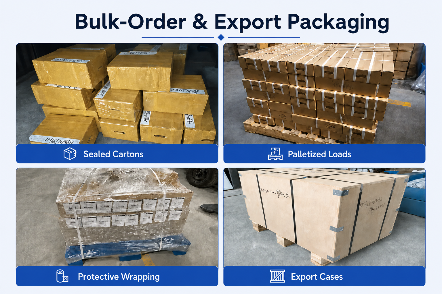
Bulk-Order & Export Packaging
Bulk shipments can be arranged with reinforced cartons, protective wrapping, palletized loading or export cases according to order quantity, shipment weight and agreed transportation requirements.
Delivery Coordination
Production completion, packing method and dispatch arrangements are confirmed according to the approved order. Courier, air, sea or customer-designated shipping options can be reviewed according to shipment size and destination. Final lead time is confirmed after product specifications, quantity and packaging requirements are approved.
Product & Application FAQs
Common questions about the PCD Combination End Mill for milling, chamfering and precision profile machining of aluminum, copper and other non-ferrous materials.
What operations can this PCD combination end mill perform?
What is the advantage of combining milling and chamfering in one tool?
Which materials is this PCD cutter suitable for?
Why is PCD used for non-ferrous machining?
Can the chamfer angle and milling profile be customized?
Can this tool be used for steel machining?
What should be considered when setting cutting parameters?
Ordering & Customization FAQs
Ordering information for distributors, tooling suppliers and OEM customers requiring standard or custom PCD combination milling and chamfering cutters.
Are standard and custom sizes available?
Can you manufacture a cutter from my component drawing?
Can the PCD edge configuration be customized?
Are OEM marking and private-label packaging available?
Thời gian thực hiện thông thường là bao lâu?
What information should I provide for quotation?
Technical Downloads
Reference documents for solid carbide and special milling tool selection and machining-data review.
Cutting Tool Catalog
Review milling cutters and related custom cutting tool series.
Speeds & Feeds Guide
Access reference machining information for application and cutting-data review.
Need Sizes, Pricing or Custom Options?
Send us the required tool type, sizes, quantities, workpiece material and any OEM or custom requirements. We will confirm suitable specifications, availability, lead time and quotation details.
Drawings, size lists and reference photos are welcome.