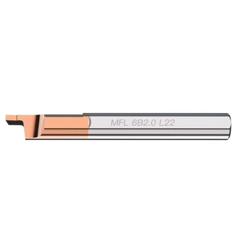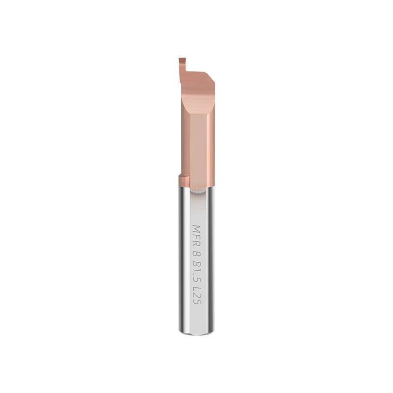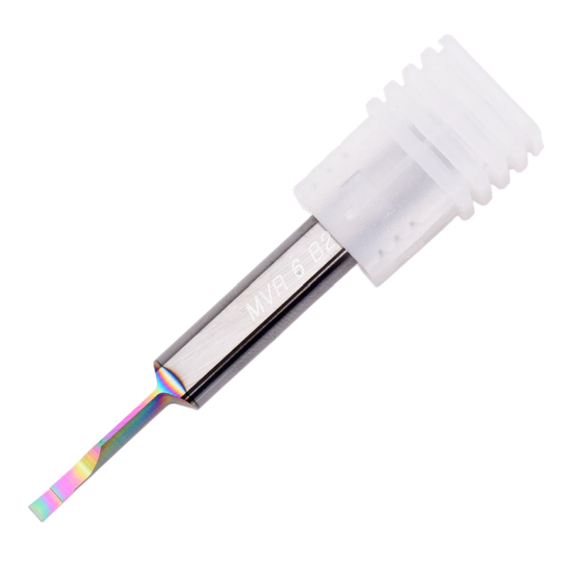


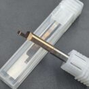


แท่งตัดร่องหน้าขนาดเล็กแบบคาร์ไบด์แข็ง MFR สำหรับรูเจาะขนาดเล็ก
Narrow Grooving
Small-Bore Access
ขนาดมาตรฐาน
ผลิตตามสั่งและ OEM
MFR Micro Face Grooving Tools for CNC Lathes
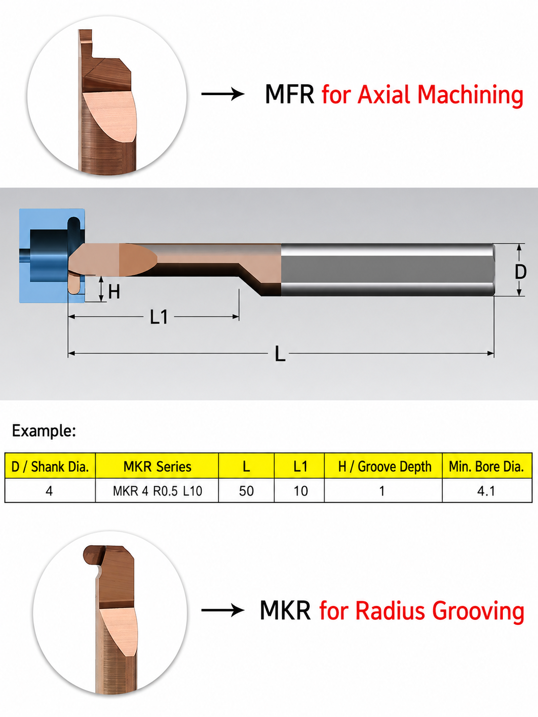
นี่ solid carbide face grooving tool enters the workpiece end face in the axial direction to produce annular grooves. Match the cutting width and tool clearance to the groove’s inner and outer diameters. Confirm groove depth, cutting direction and holder compatibility for the selected MFR model.
Micro internal tooling series — product display
Match Groove Width, Reach & Clearance
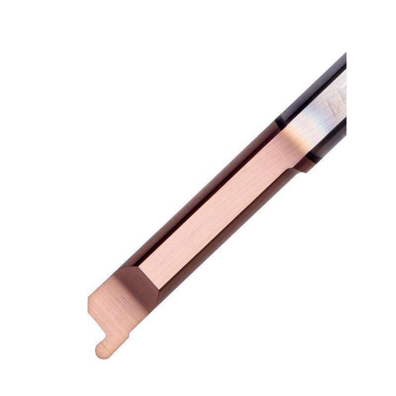
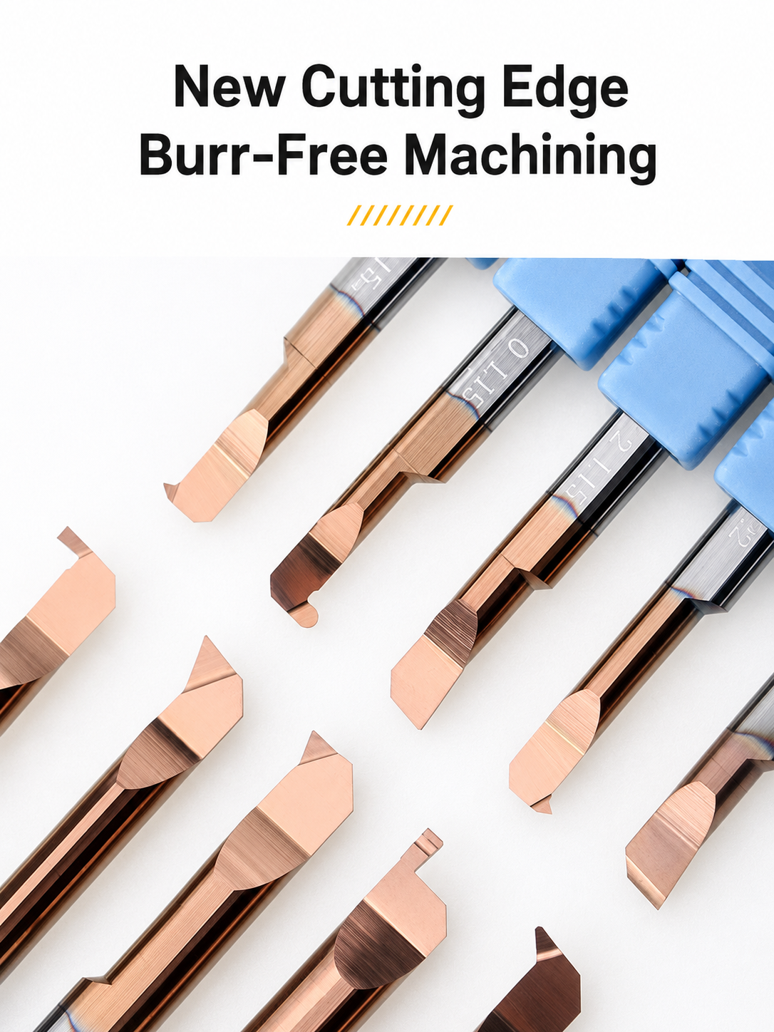
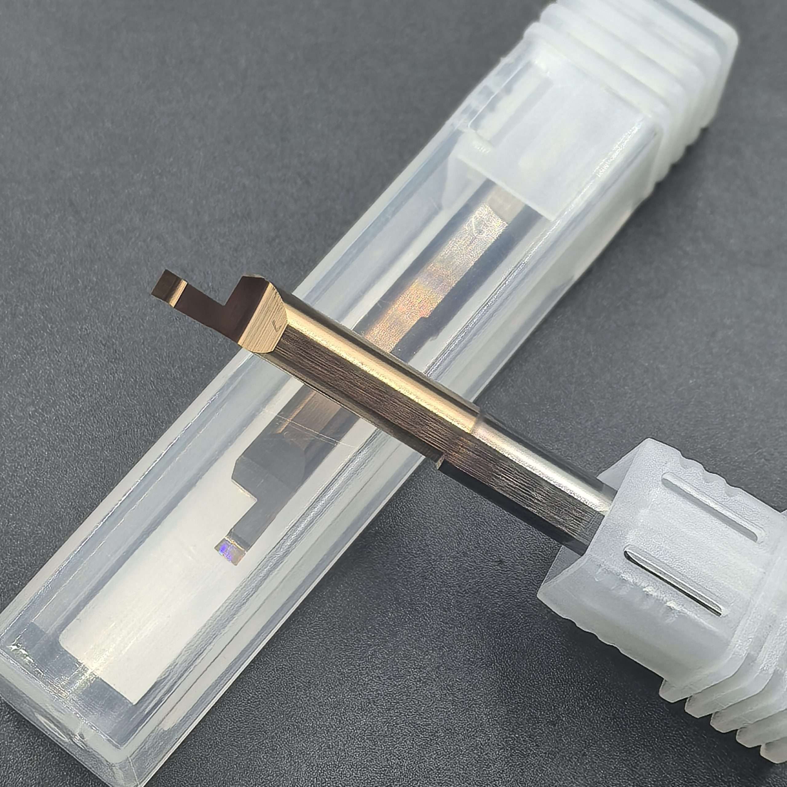
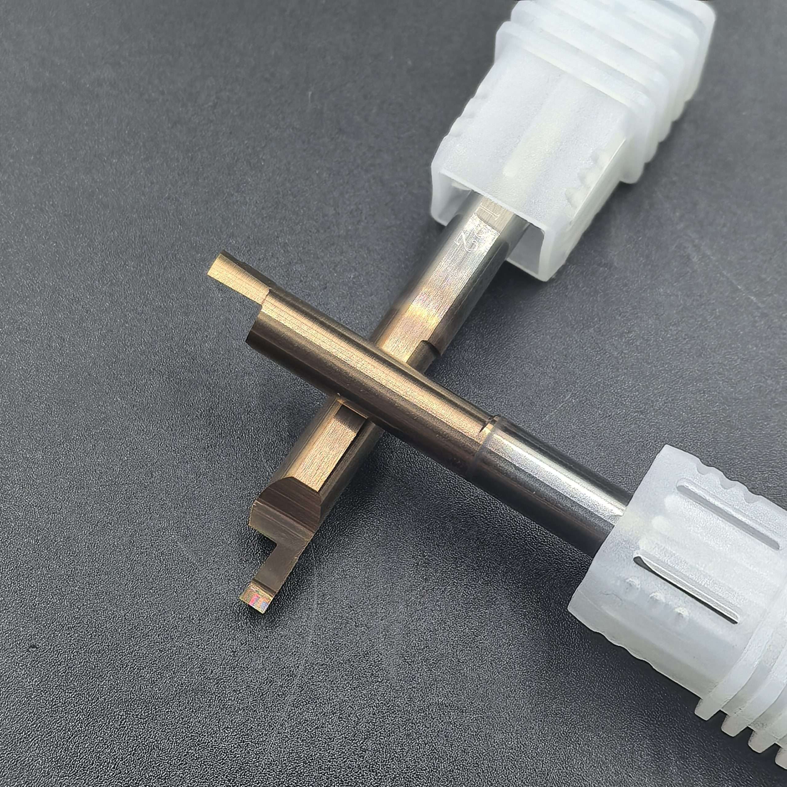
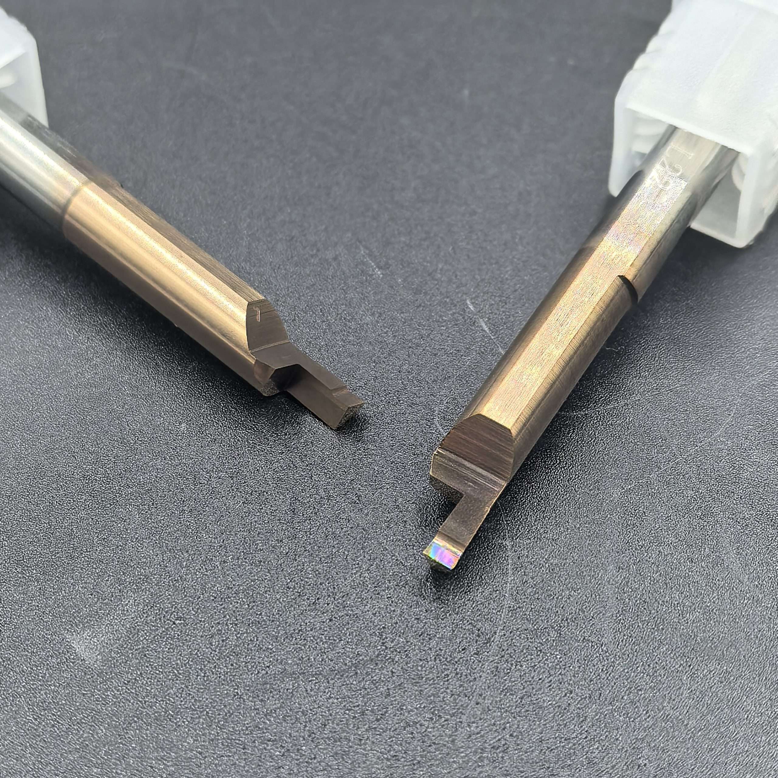
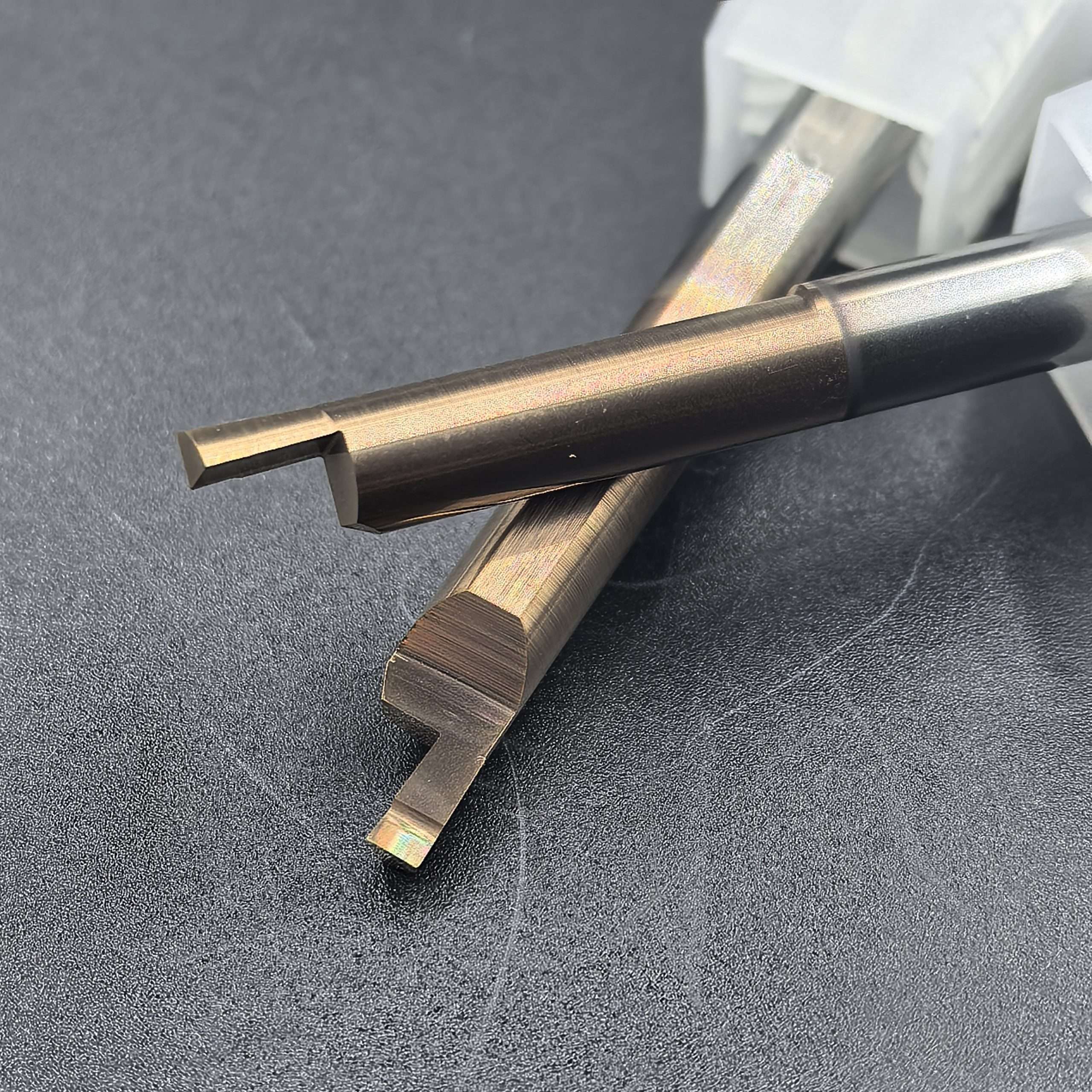
Compact Face-Grooving Profile
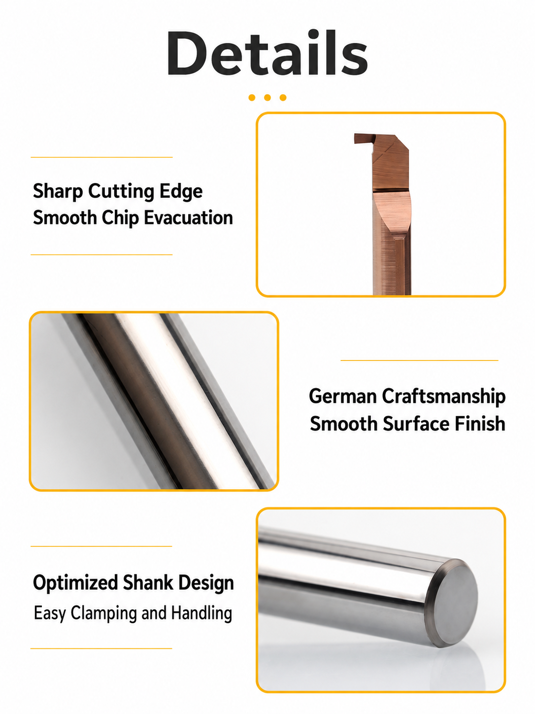
Reaches recessed end faces where bore and shoulder clearance are limited.
Precision-Ground Cutting Edge
Supports controlled groove width and consistent profile finishing.
Rigid Solid Carbide Body
Helps limit deflection with secure clamping and minimal overhang.
Standard & Custom Configurations
Select width, shank and working length by model, or request drawing-based dimensions.
Small-Bore Face Grooving Applications
- Narrow face grooves in sleeves, bushings and precision fittings.
- Recessed end-face features with restricted tool access.
- Repeat groove production on CNC lathes and Swiss-type machines with suitable holders.
เหมาะที่สุดสำหรับ: Internal end-face grooves matched to the selected tool’s width, depth and reach.
ไม่เหมาะสำหรับ: Bore-wall grooving, threading or general boring without separately matched geometry.
Tool Geometry & Application Range
Confirm groove width, axial depth, groove diameter range, bore size and access length. Check cutting direction and clearance throughout entry and retraction; shank diameter alone does not establish bore compatibility.

Material-Matched Configurations
Select cutting geometry and coating according to workpiece grade, hardness and groove requirements. Confirm material suitability for the selected MFR model.

Series material reference; configurations vary by tool.
MFR Cutting Profile & Product Details
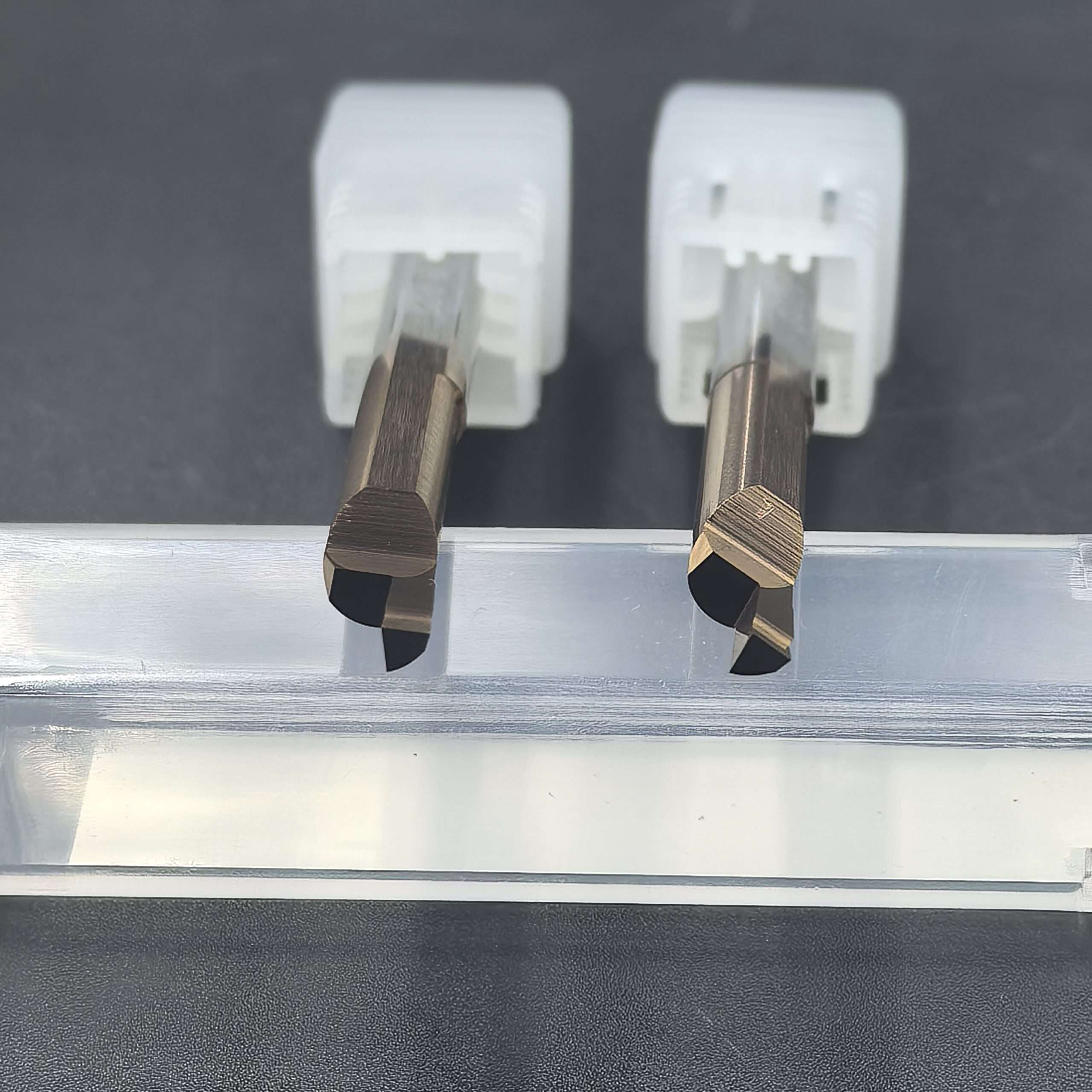
Custom Dimensions & OEM Supply
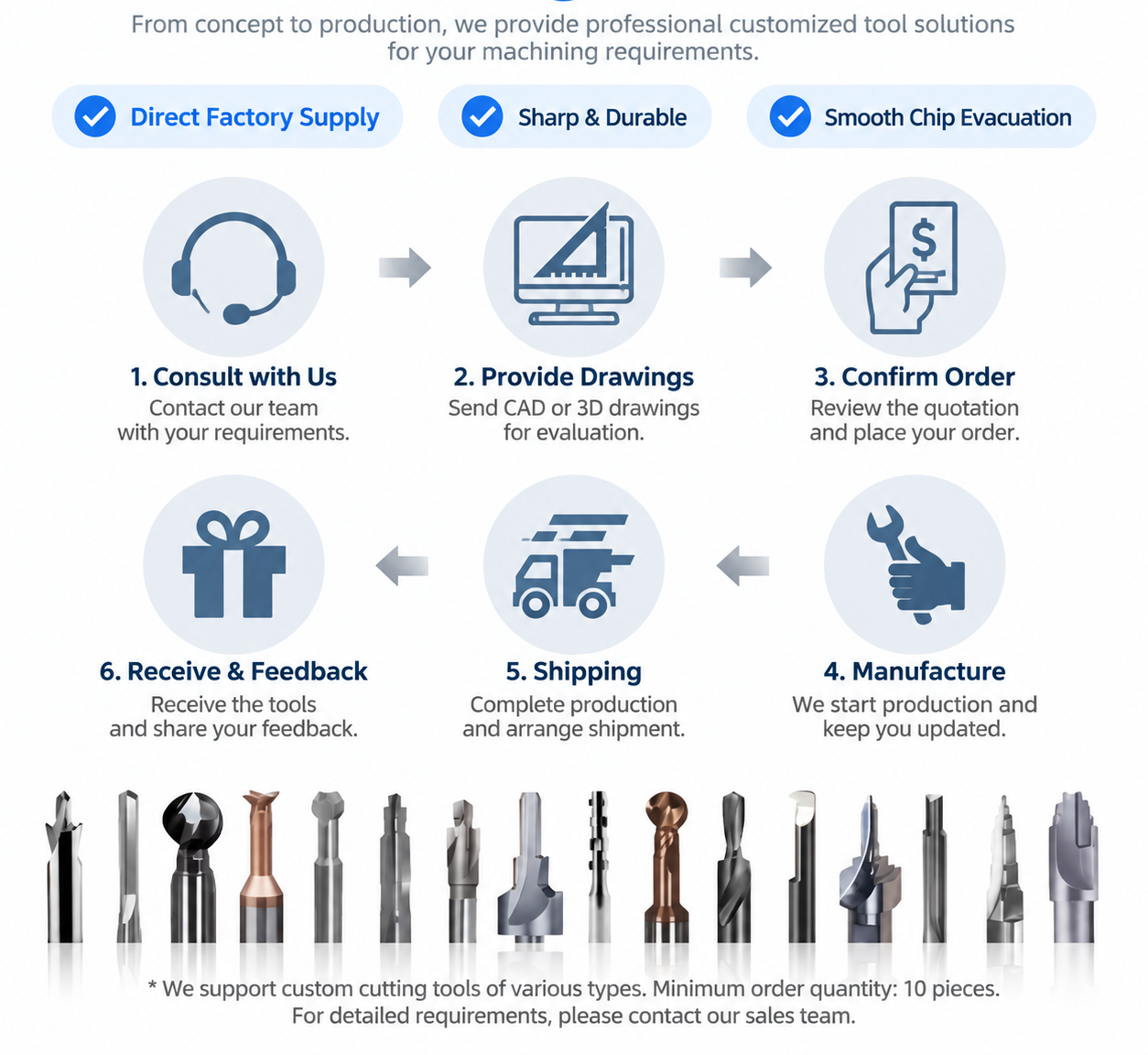
Drawing-based widths, reach, shanks, cutting profiles and coatings can be reviewed for non-standard grooves. Laser marking and private-label packaging support distributor and repeat orders.
MFR Micro Face Grooving Bar Specifications
Select MFR solid carbide face grooving bars by groove width, cutting depth, bore clearance and reach. All dimensions are in millimeters.
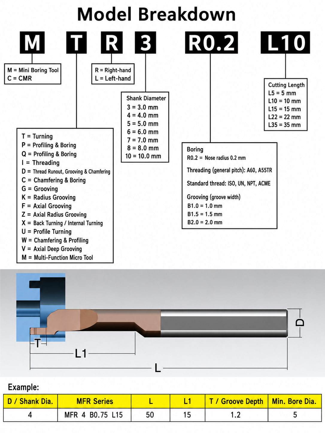
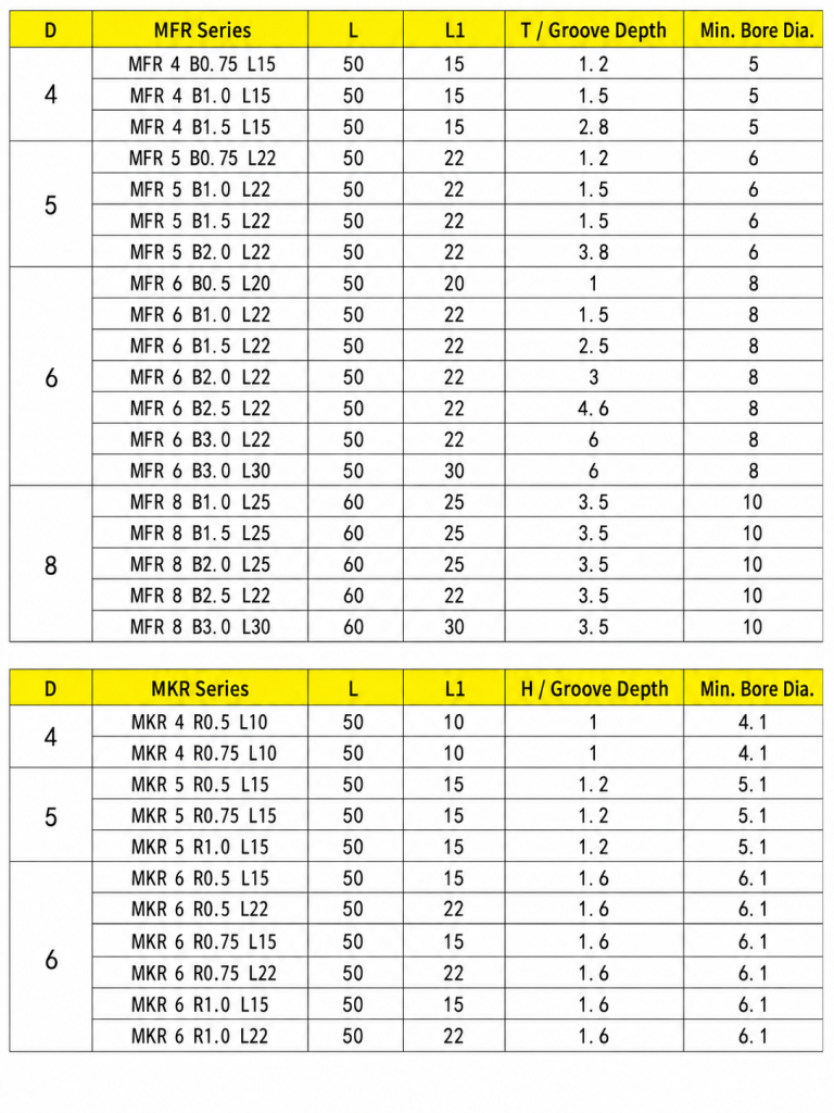
Model example: MFR 4 B0.75 L15 = MFR series · Ø4 shank · 0.75 cutting width · 15 working length.
MFR Standard Models
| แบบ | Shank D | OAL L | Reach L1 | Depth T | Min. Bore Ø |
|---|---|---|---|---|---|
| MFR 4 B0.75 L15 | 4 | 50 | 15 | 1.2 | 5 |
| MFR 4 B1.0 L15 | 4 | 50 | 15 | 1.5 | 5 |
| MFR 4 B1.5 L15 | 4 | 50 | 15 | 2.8 | 5 |
| MFR 5 B0.75 L22 | 5 | 50 | 22 | 1.2 | 6 |
| MFR 5 B1.0 L22 | 5 | 50 | 22 | 1.5 | 6 |
| MFR 5 B1.5 L22 | 5 | 50 | 22 | 1.5 | 6 |
| MFR 5 B2.0 L22 | 5 | 50 | 22 | 3.8 | 6 |
| MFR 6 B0.5 L20 | 6 | 50 | 20 | 1.0 | 8 |
| MFR 6 B1.0 L22 | 6 | 50 | 22 | 1.5 | 8 |
| MFR 6 B1.5 L22 | 6 | 50 | 22 | 2.5 | 8 |
| MFR 6 B2.0 L22 | 6 | 50 | 22 | 3.0 | 8 |
| MFR 6 B2.5 L22 | 6 | 50 | 22 | 4.6 | 8 |
| MFR 6 B3.0 L22 | 6 | 50 | 22 | 6.0 | 8 |
| MFR 6 B3.0 L30 | 6 | 50 | 30 | 6.0 | 8 |
| MFR 8 B1.0 L25 | 8 | 60 | 25 | 3.5 | 10 |
| MFR 8 B1.5 L25 | 8 | 60 | 25 | 3.5 | 10 |
| MFR 8 B2.0 L25 | 8 | 60 | 25 | 3.5 | 10 |
| MFR 8 B2.5 L22 | 8 | 60 | 22 | 3.5 | 10 |
| MFR 8 B3.0 L30 | 8 | 60 | 30 | 3.5 | 10 |
B indicates nominal cutting width. T and L1 are separate dimensions; confirm model limits and availability before ordering.
ต้องการทราบขนาด ราคา หรือตัวเลือกการปรับแต่งตามความต้องการหรือไม่?
Send your model or groove drawing, workpiece material and quantity for size confirmation and quotation.
What is the difference between face grooving and internal grooving?
Face grooving produces an annular groove by feeding into the workpiece end face. Internal grooving produces a groove on the bore wall through radial feed. The tool geometry and clearance requirements differ.Selection Checks
- Match groove width, depth and diameter range to the cutting profile.
- Check minimum bore size and full entry, cutting and retraction clearance.
- Choose the shortest suitable reach and confirm holder fit and cutting direction.
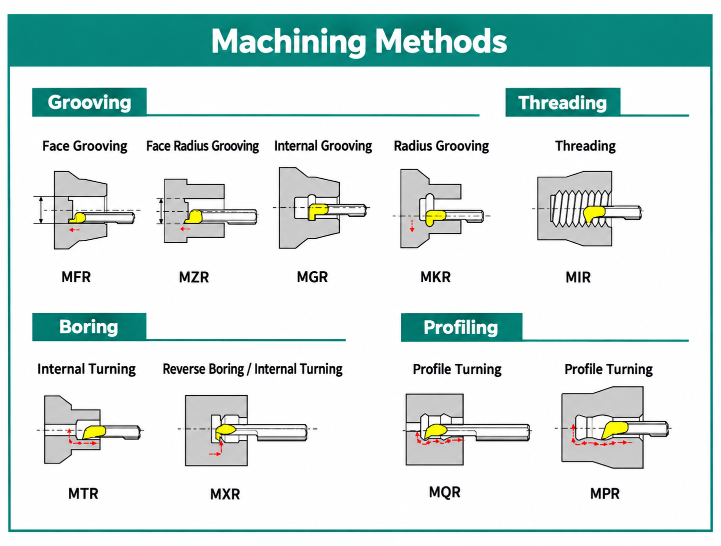
Related Face Grooving Tools
MFR Micro Face Grooving Bar Customization
Custom groove widths, cutting depths, working lengths and shanks are available for MFR solid carbide micro face grooving bars, subject to drawing review.
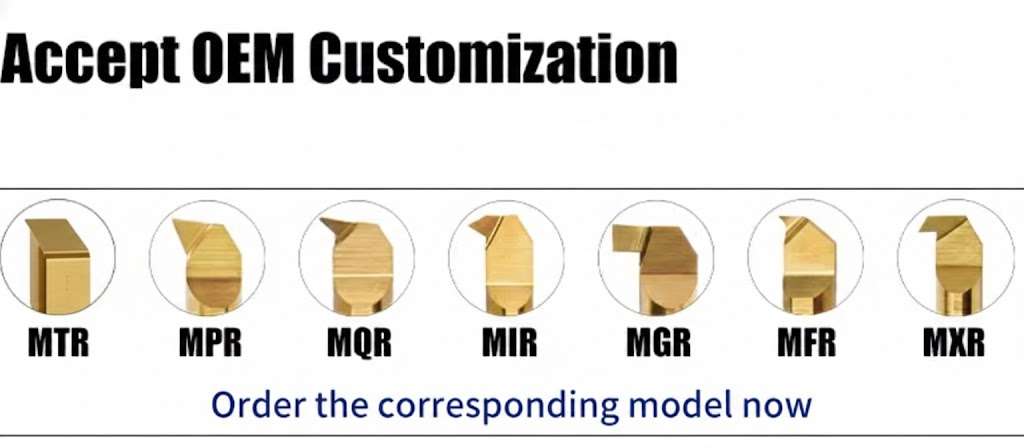
OEM & Private-Label Options
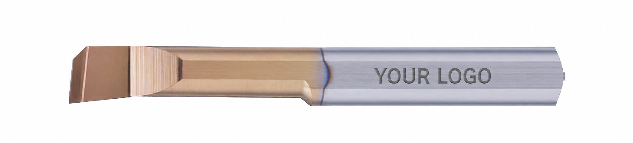
การพิมพ์ด้วยเลเซอร์
Logos and model codes, subject to shank space.
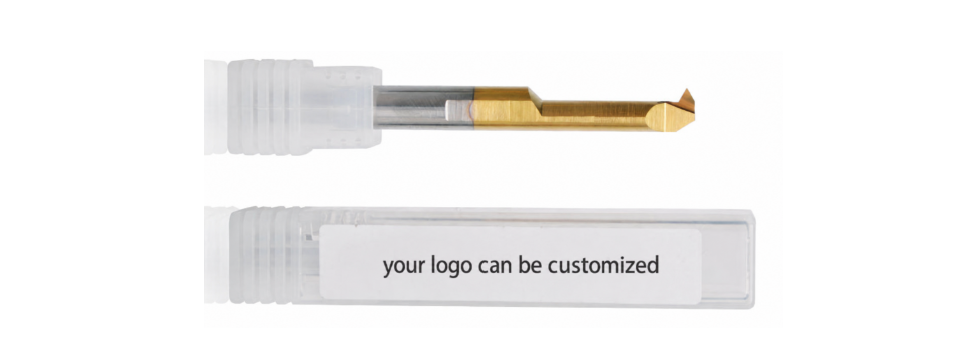
บรรจุภัณฑ์แบรนด์ส่วนตัว
Branded labels and protective packaging.
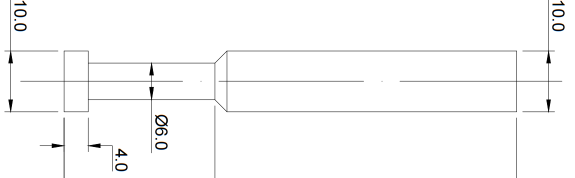
แบบวาดและข้อมูลทางเทคนิค
Approved dimensions for repeat orders.
ขั้นตอนการสั่งทำตามความต้องการ
Requirement review → Drawing approval → Samples where required → Production & inspection.
MFR Grooving Bar Quality & Delivery
Material checks, grinding control and final inspection verify MFR face grooving bars against confirmed specifications or approved drawings.

จุดตรวจสอบสำคัญ
- วัสดุ: ประเภทคาร์ไบด์และข้อมูลจำเพาะของชิ้นงานดิบ.
- เรขาคณิต: Cutting width, depth, corner profile and edge condition.
- ขนาด: Working length, shank size and overall length.
- การระบุตัวตน: Model, marking and packaging labels.
Batch-record requirements are confirmed with the order.
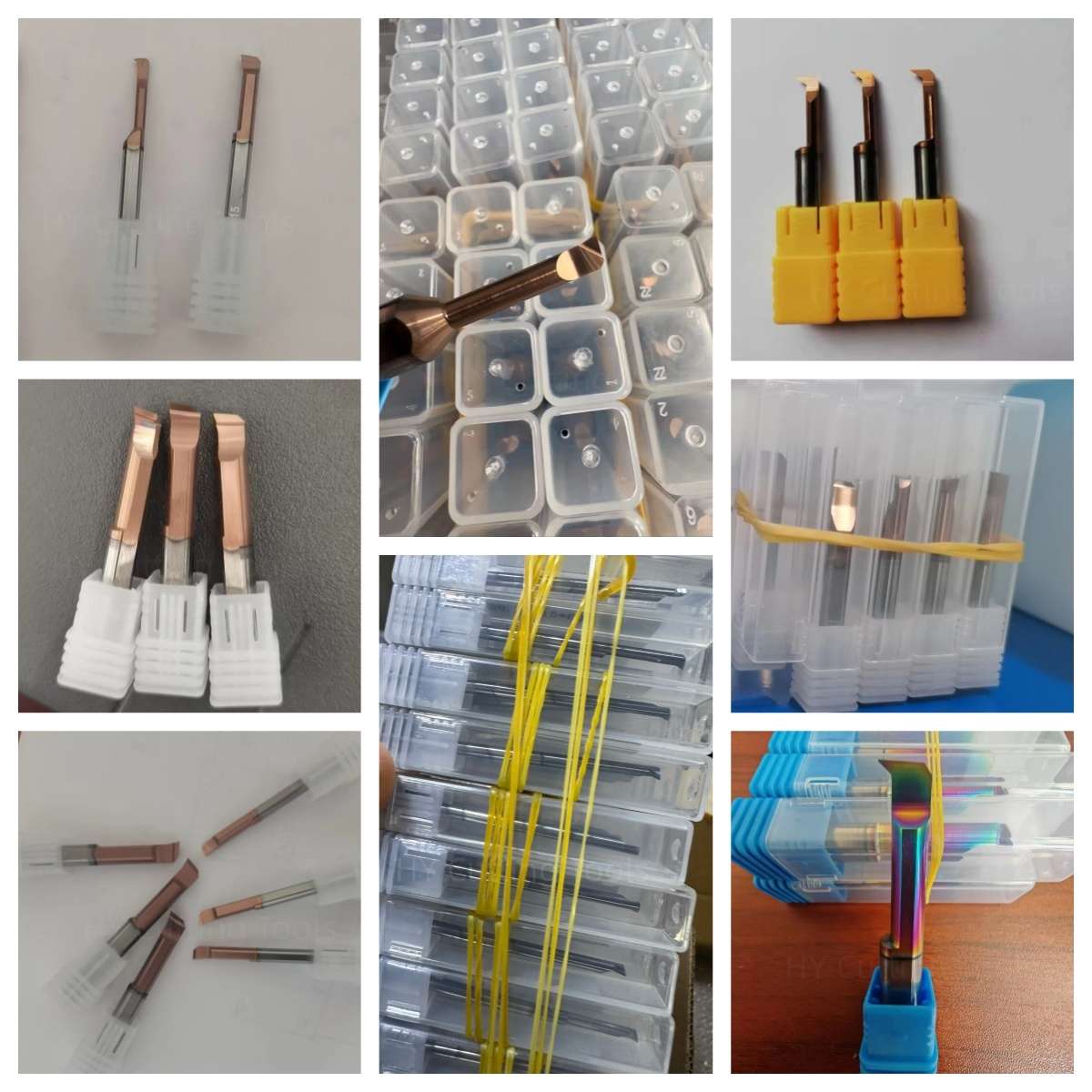
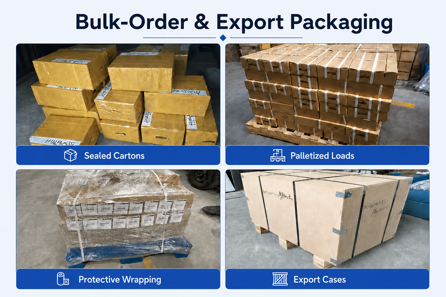
Tool Protection & Export Packing
Individual protection, clear labels and outer packing help protect cutting edges during storage and transport.

ระยะเวลาการผลิตและการจัดส่ง
เครื่องมือมาตรฐาน: โดยทั่วไป 1–3 วันทำงาน ขึ้นอยู่กับสต็อก.
เครื่องมือที่ปรับแต่งได้: Lead time confirmed by geometry, coating, quantity and production requirements.

MFR Micro Face Grooving Bar FAQs
Is MFR suitable for face grooves inside small bores?
Which MFR shank size fits my bore diameter?
The listed minimum bores are Ø5 mm for Ø4 shanks, Ø6 mm for Ø5 shanks, Ø8 mm for Ø6 shanks and Ø10 mm for Ø8 shanks.
Also confirm groove diameters, head clearance and the complete entry and retraction path. Minimum bore size alone does not establish suitability.
What groove widths and cutting depths are available?
How do I choose the correct working length?
Can MFR grooving bars machine stainless steel or aluminum?
Custom Orders & Supply
Can I order custom widths, reach or OEM packaging?
What is the MOQ, and can I mix MFR models?
What should I send for pricing and delivery confirmation?
Selection & Technical Resources
ต้องการทราบขนาด ราคา หรือตัวเลือกการปรับแต่งตามความต้องการหรือไม่?
ส่งรายละเอียดและจำนวนที่ต้องการเพื่อรับใบเสนอราคา.
- ขนาดมาตรฐาน
- คำสั่งซื้อทดลองในปริมาณน้อย
- ขนาดผสม
- OEM และตามสั่ง
ดูรหัส QR – ติดต่อฝ่ายขายผ่าน WeChat

สแกนเพื่อติดต่อเราผ่าน WeChat.
สแกนเพื่อติดต่อเราผ่าน WeChat.