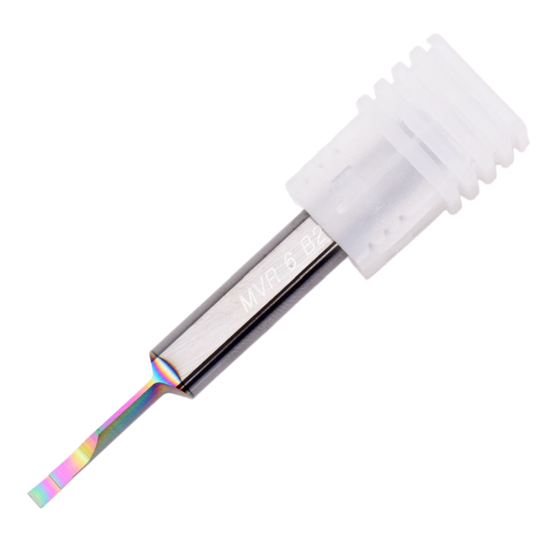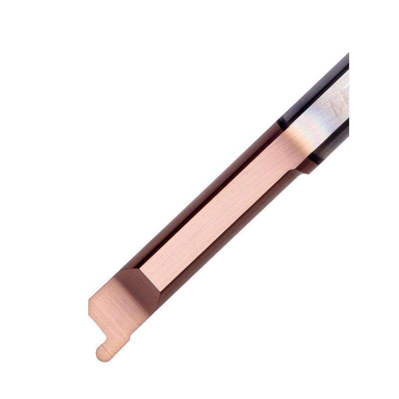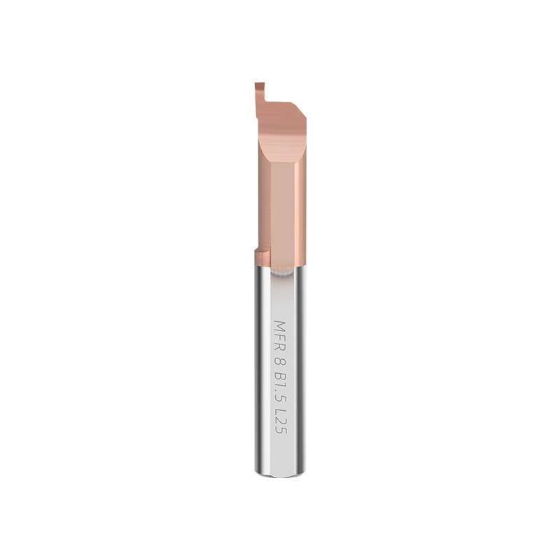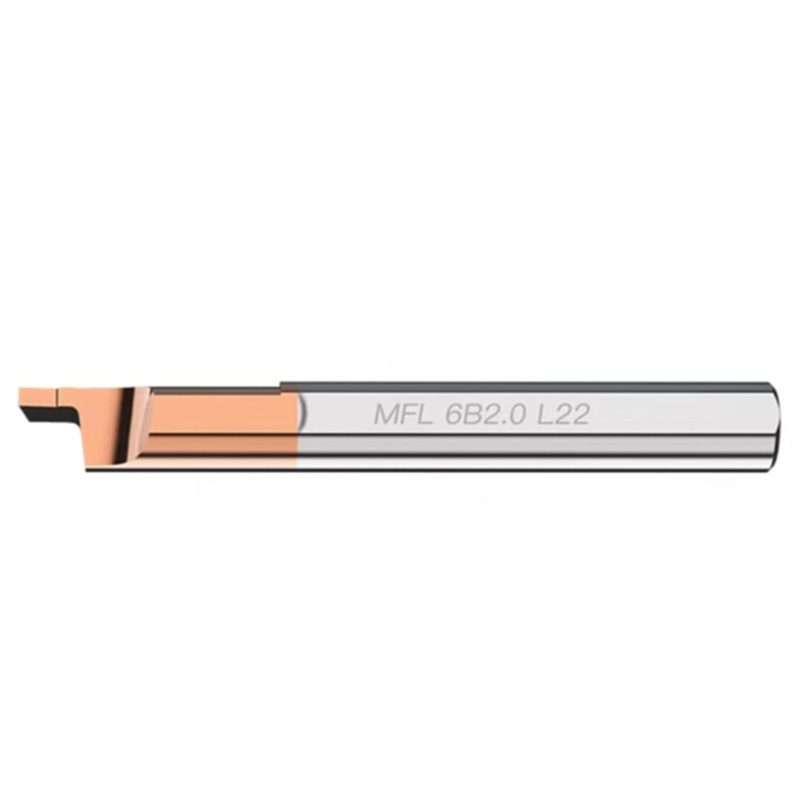




قضبان تخديد وجهي داخلي MFR من الكربيد الصلب لتشغيل مجاري دقيقة في الثقوب الصغيرة
Narrow Grooving
الوصول عبر فتحات صغيرة
الأحجام القياسية
المنتجات المخصصة وOEM
MFR Micro Face Grooving Tools for CNC Lathes
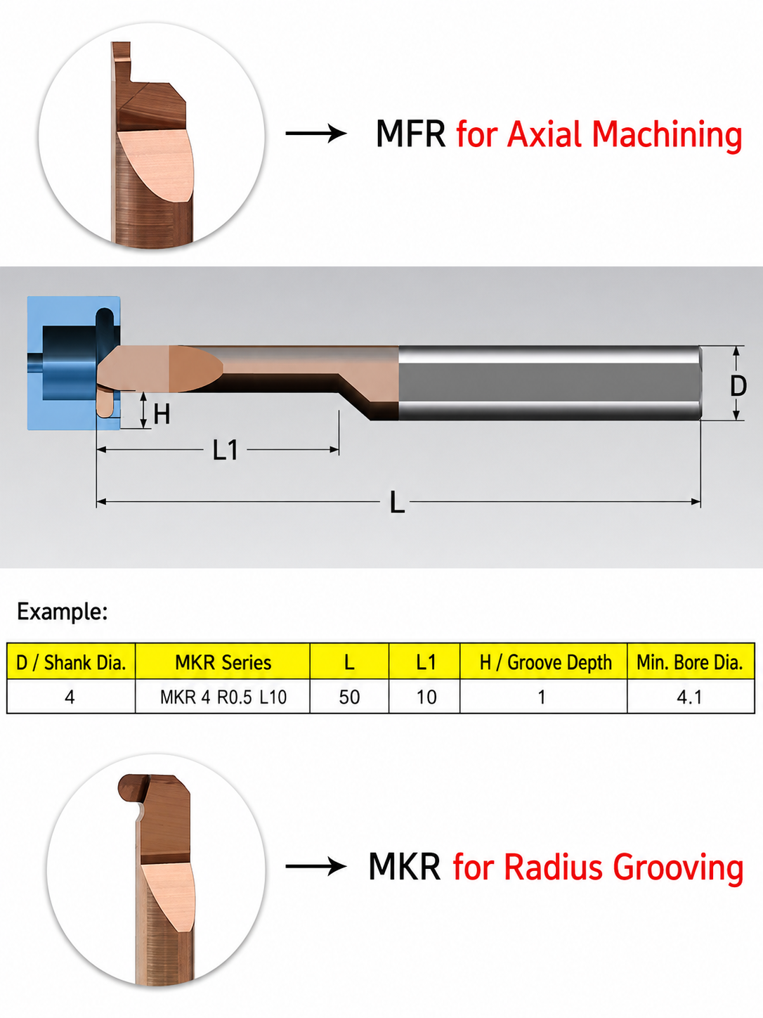
هذا solid carbide face grooving tool enters the workpiece end face in the axial direction to produce annular grooves. Match the cutting width and tool clearance to the groove’s inner and outer diameters. Confirm groove depth, cutting direction and holder compatibility for the selected MFR model.
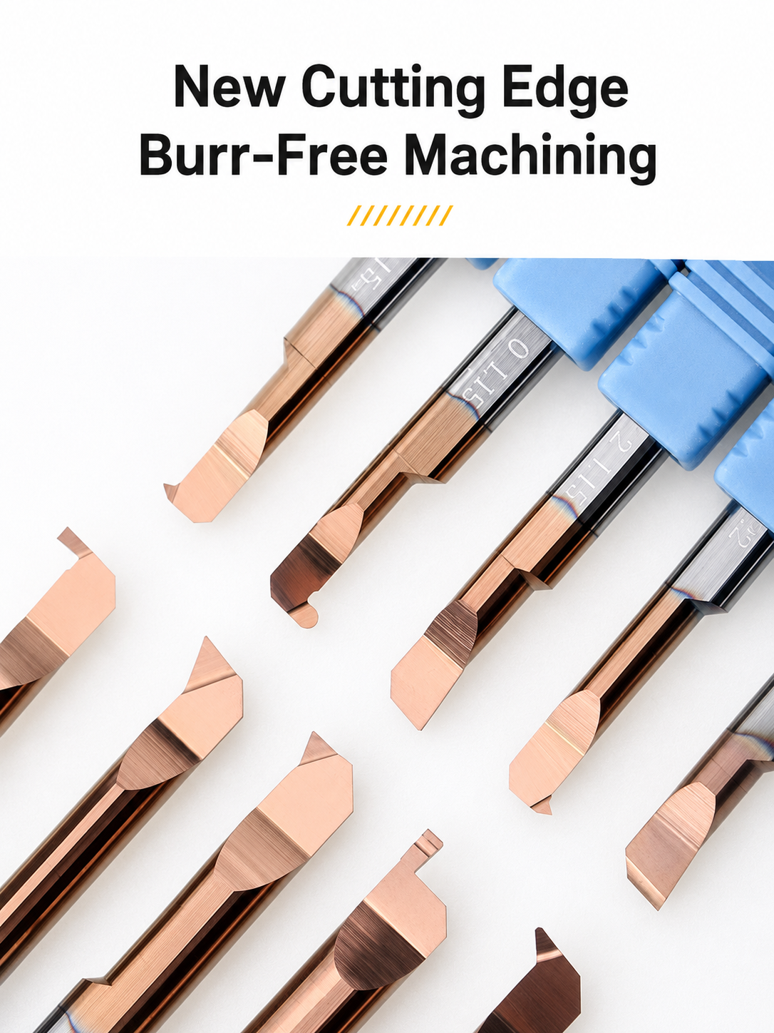
Micro internal tooling series — product display
Match Groove Width, Reach & Clearance
Compact Face-Grooving Profile
Reaches recessed end faces where bore and shoulder clearance are limited.
حافة قطع مصقولة بدقة
Supports controlled groove width and consistent profile finishing.
Rigid Solid Carbide Body
Helps limit deflection with secure clamping and minimal overhang.
Standard & Custom Configurations
Select width, shank and working length by model, or request drawing-based dimensions.
Small-Bore Face Grooving Applications
- Narrow face grooves in sleeves, bushings and precision fittings.
- Recessed end-face features with restricted tool access.
- Repeat groove production on CNC lathes and Swiss-type machines with suitable holders.
الأفضل لـ Internal end-face grooves matched to the selected tool’s width, depth and reach.
ليس مناسبًا لـ: Bore-wall grooving, threading or general boring without separately matched geometry.
Tool Geometry & Application Range
Confirm groove width, axial depth, groove diameter range, bore size and access length. Check cutting direction and clearance throughout entry and retraction; shank diameter alone does not establish bore compatibility.

Material-Matched Configurations
Select cutting geometry and coating according to workpiece grade, hardness and groove requirements. Confirm material suitability for the selected MFR model.

Series material reference; configurations vary by tool.
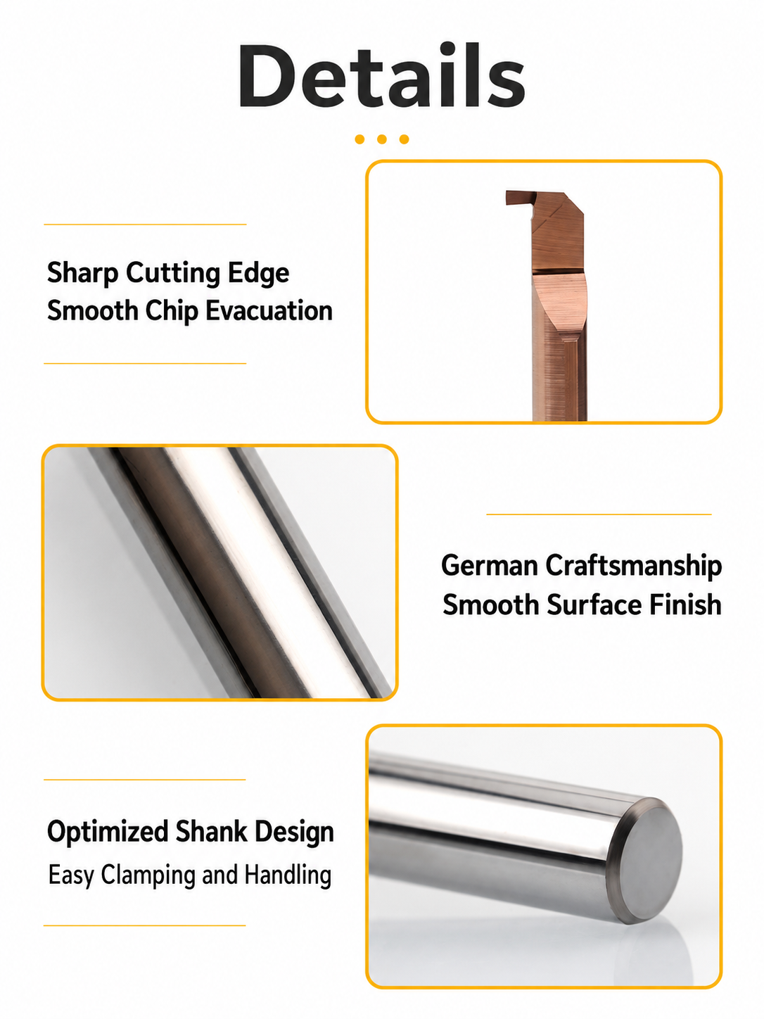
MFR Cutting Profile & Product Details
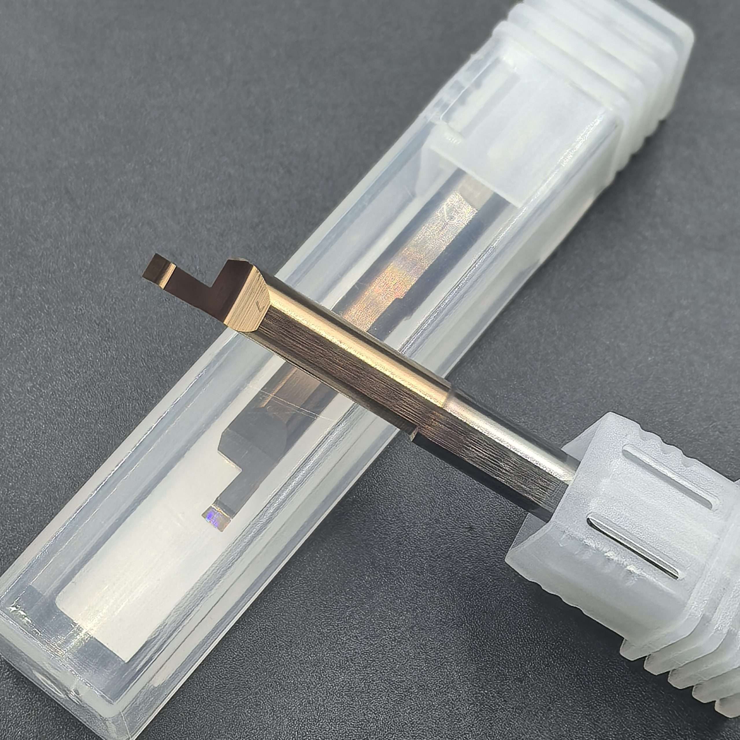
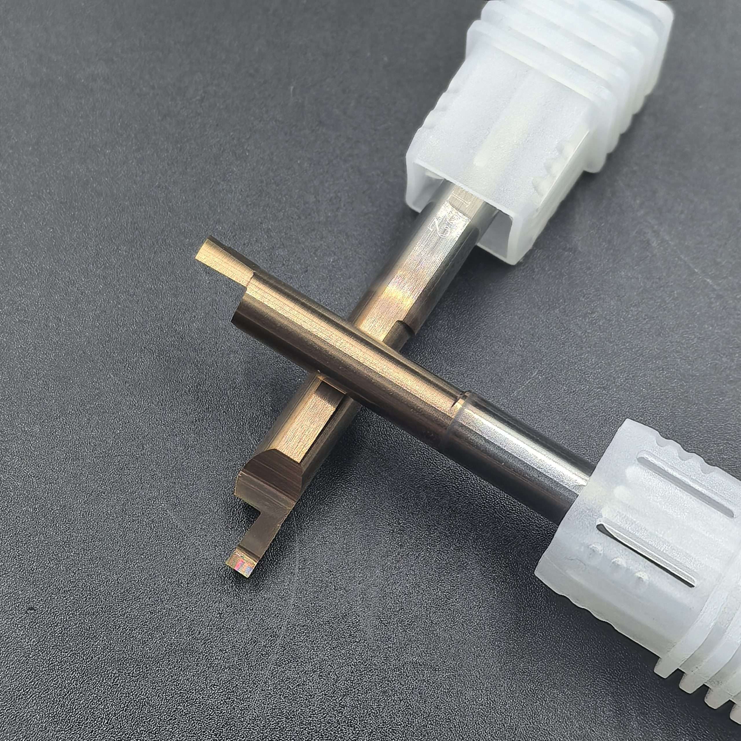
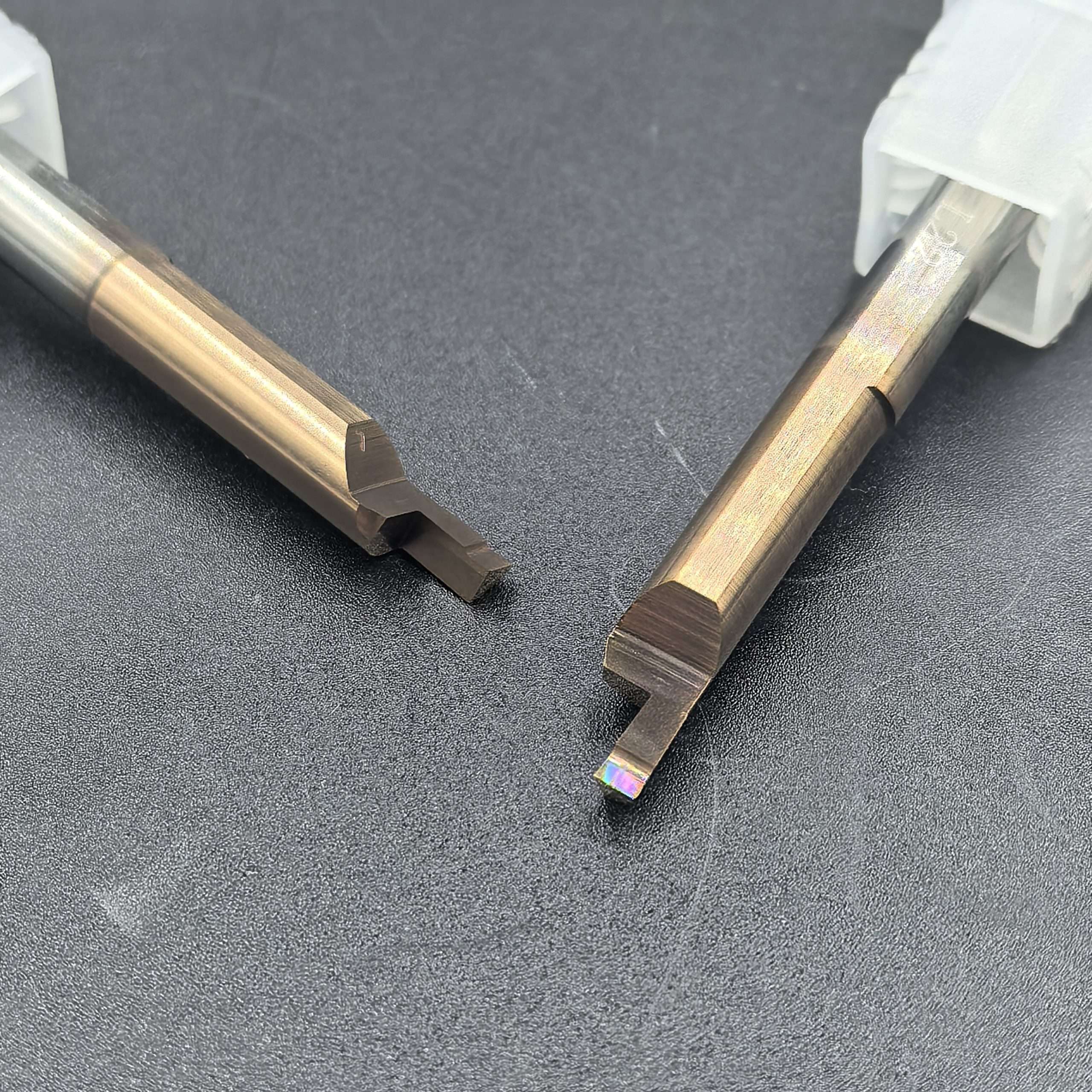
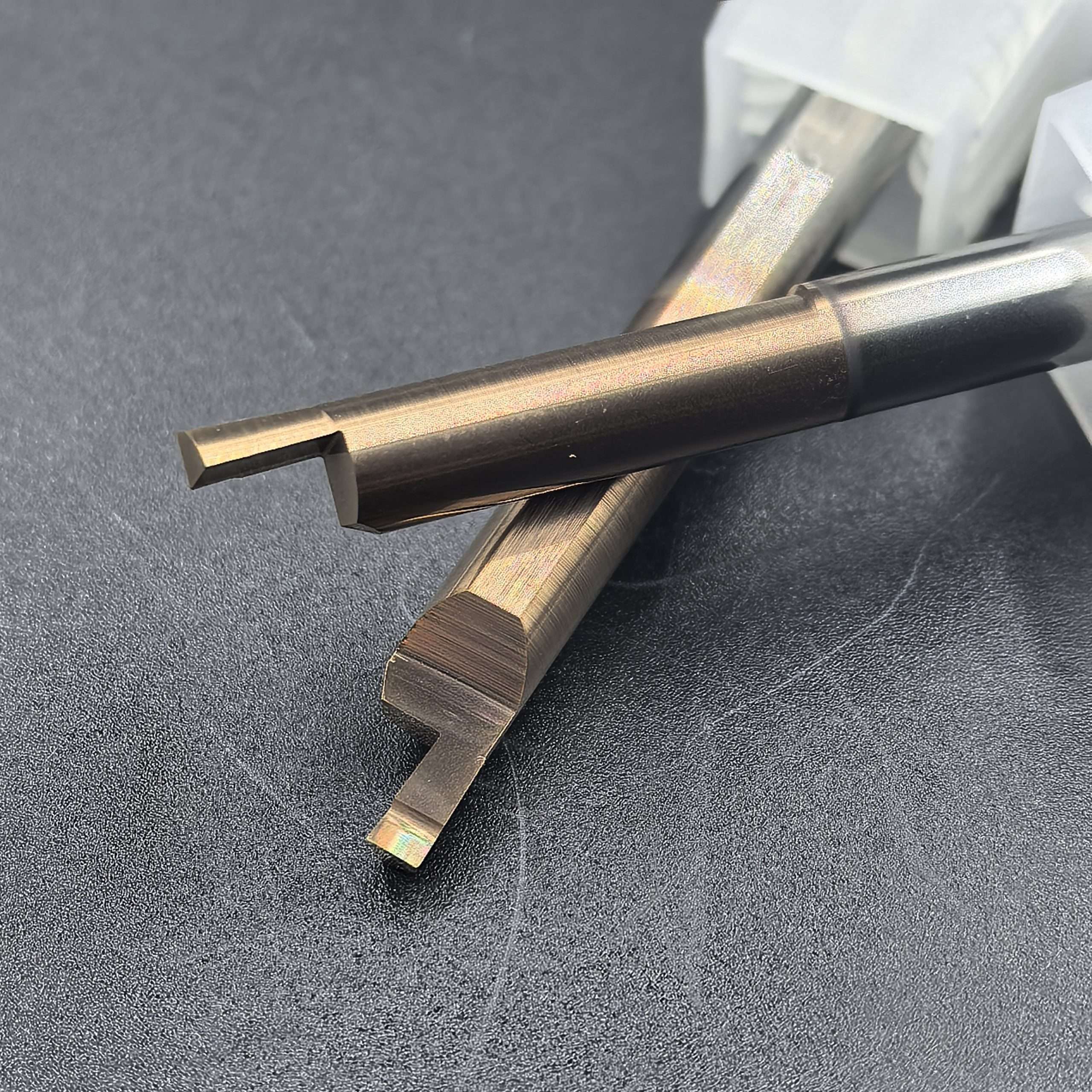
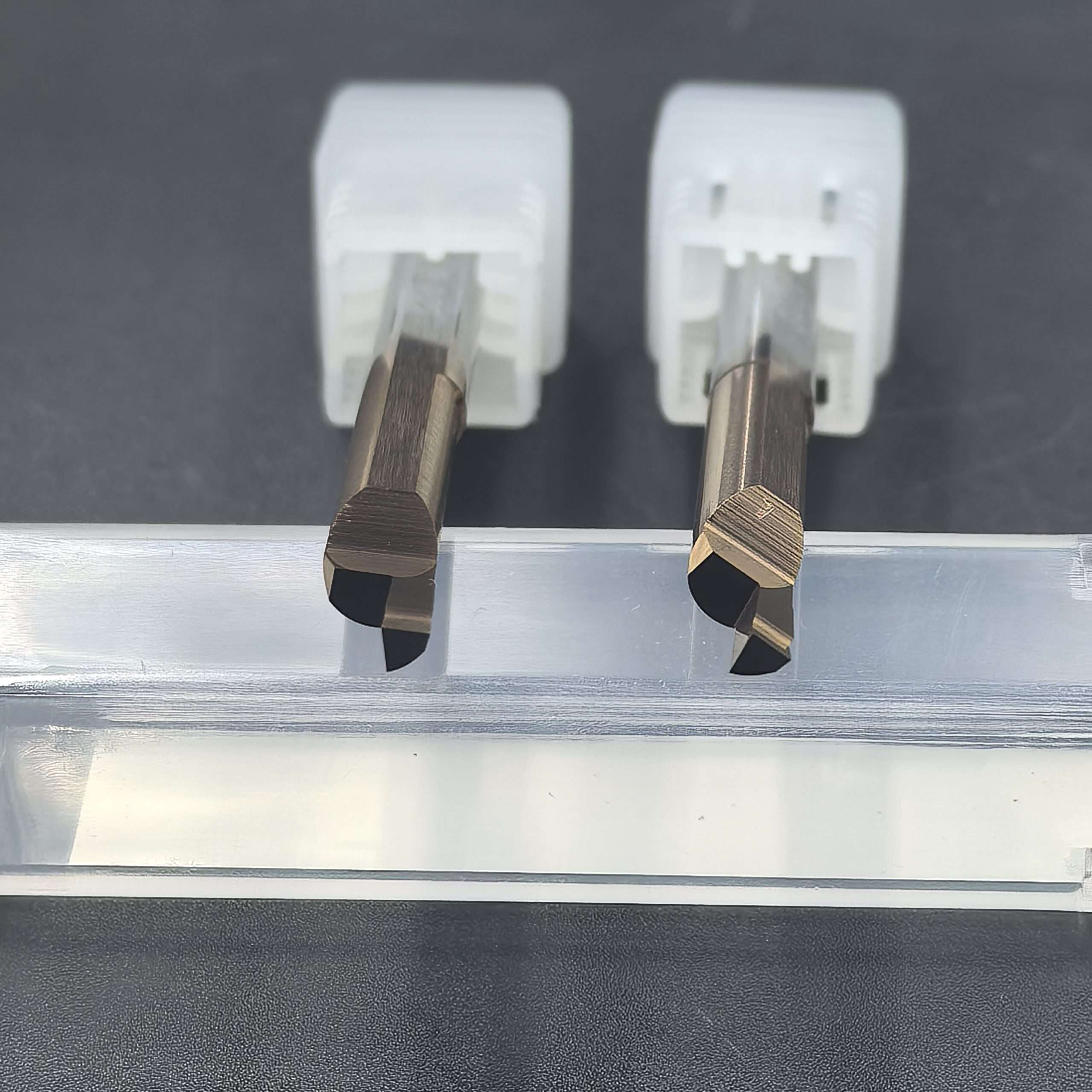
الأبعاد المخصصة والتوريد وفقًا لمواصفات المصنع الأصلي (OEM)
Drawing-based widths, reach, shanks, cutting profiles and coatings can be reviewed for non-standard grooves. Laser marking and private-label packaging support distributor and repeat orders.
MFR Micro Face Grooving Bar Specifications
Select MFR solid carbide face grooving bars by groove width, cutting depth, bore clearance and reach. All dimensions are in millimeters.
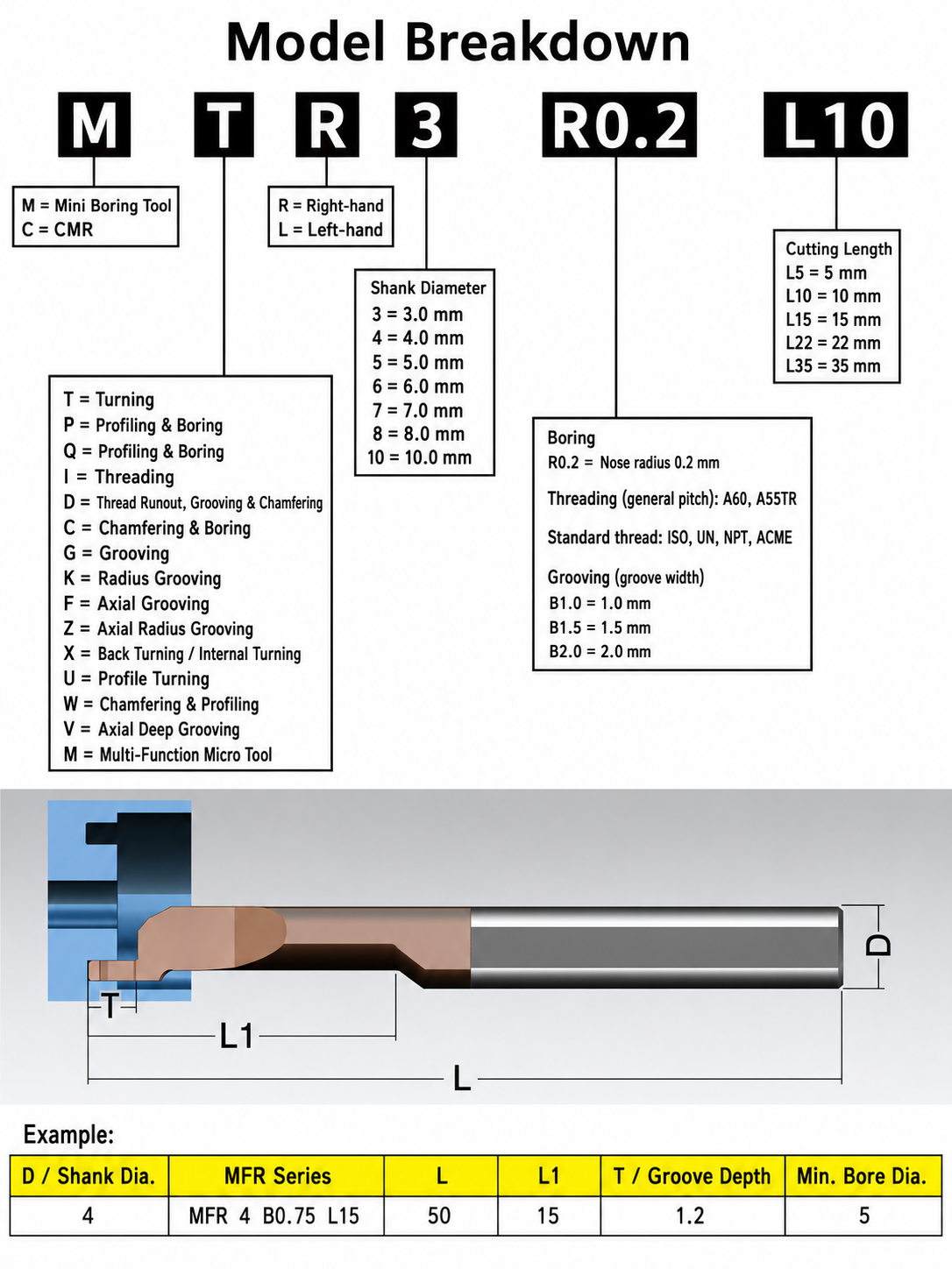
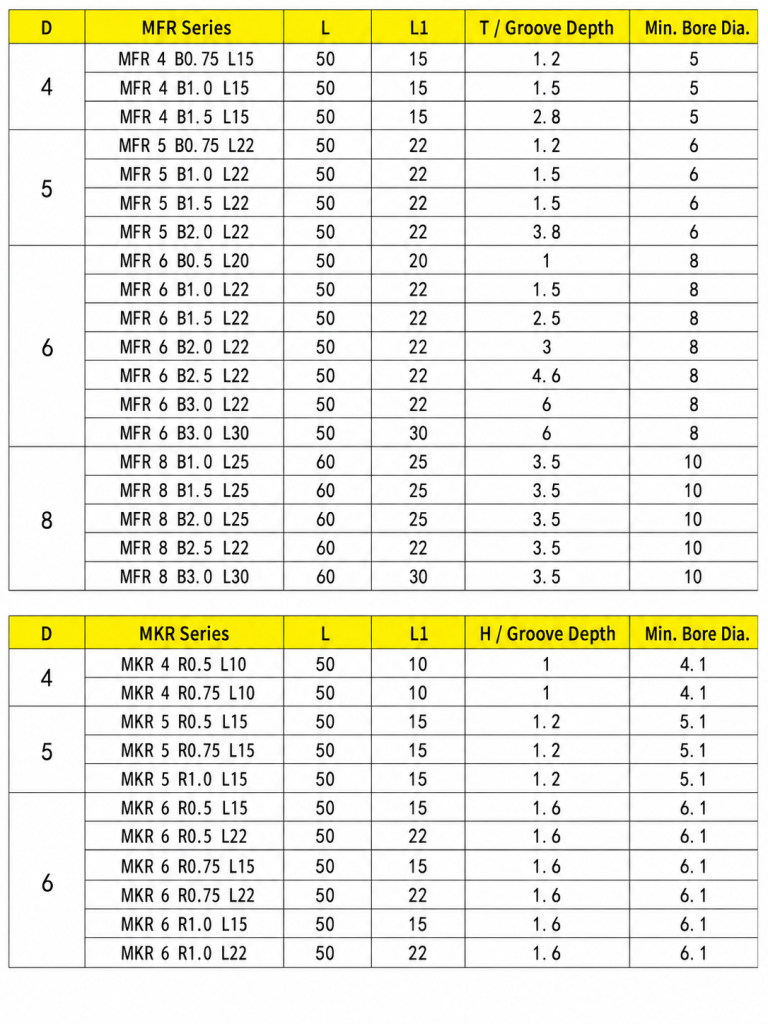
Model example: MFR 4 B0.75 L15 = MFR series · Ø4 shank · 0.75 cutting width · 15 working length.
MFR Standard Models
| الطراز | شانك د | OAL L | Reach L1 | Depth T | Min. Bore Ø |
|---|---|---|---|---|---|
| MFR 4 B0.75 L15 | 4 | 50 | 15 | 1.2 | 5 |
| MFR 4 B1.0 L15 | 4 | 50 | 15 | 1.5 | 5 |
| MFR 4 B1.5 L15 | 4 | 50 | 15 | 2.8 | 5 |
| MFR 5 B0.75 L22 | 5 | 50 | 22 | 1.2 | 6 |
| MFR 5 B1.0 L22 | 5 | 50 | 22 | 1.5 | 6 |
| MFR 5 B1.5 L22 | 5 | 50 | 22 | 1.5 | 6 |
| MFR 5 B2.0 L22 | 5 | 50 | 22 | 3.8 | 6 |
| MFR 6 B0.5 L20 | 6 | 50 | 20 | 1.0 | 8 |
| MFR 6 B1.0 L22 | 6 | 50 | 22 | 1.5 | 8 |
| MFR 6 B1.5 L22 | 6 | 50 | 22 | 2.5 | 8 |
| MFR 6 B2.0 L22 | 6 | 50 | 22 | 3.0 | 8 |
| MFR 6 B2.5 L22 | 6 | 50 | 22 | 4.6 | 8 |
| MFR 6 B3.0 L22 | 6 | 50 | 22 | 6.0 | 8 |
| MFR 6 B3.0 L30 | 6 | 50 | 30 | 6.0 | 8 |
| MFR 8 B1.0 L25 | 8 | 60 | 25 | 3.5 | 10 |
| MFR 8 B1.5 L25 | 8 | 60 | 25 | 3.5 | 10 |
| MFR 8 B2.0 L25 | 8 | 60 | 25 | 3.5 | 10 |
| MFR 8 B2.5 L22 | 8 | 60 | 22 | 3.5 | 10 |
| MFR 8 B3.0 L30 | 8 | 60 | 30 | 3.5 | 10 |
B indicates nominal cutting width. T and L1 are separate dimensions; confirm model limits and availability before ordering.
هل تحتاج إلى معلومات عن المقاسات أو الأسعار أو الخيارات المخصصة؟
Send your model or groove drawing, workpiece material and quantity for size confirmation and quotation.
What is the difference between face grooving and internal grooving?
Face grooving produces an annular groove by feeding into the workpiece end face. Internal grooving produces a groove on the bore wall through radial feed. The tool geometry and clearance requirements differ.Selection Checks
- Match groove width, depth and diameter range to the cutting profile.
- Check minimum bore size and full entry, cutting and retraction clearance.
- Choose the shortest suitable reach and confirm holder fit and cutting direction.
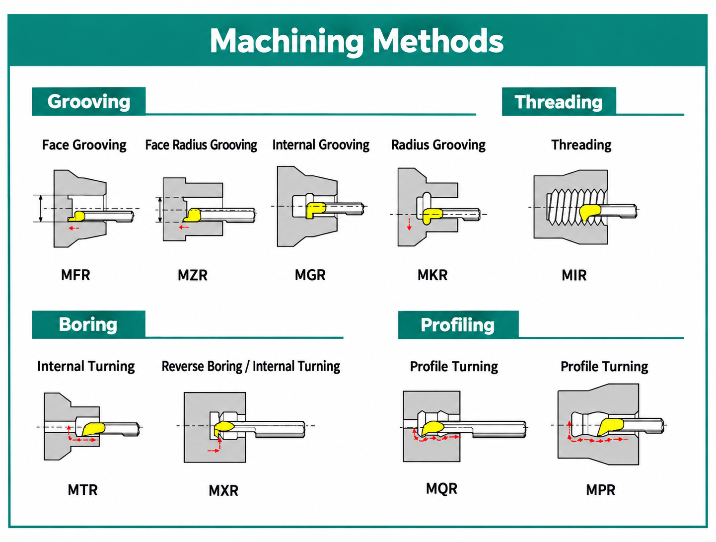
Related Face Grooving Tools
MFR Micro Face Grooving Bar Customization
Custom groove widths, cutting depths, working lengths and shanks are available for MFR solid carbide micro face grooving bars, subject to drawing review.
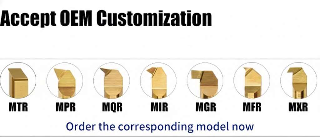
خيارات التصنيع الأصلي (OEM) والعلامات التجارية الخاصة
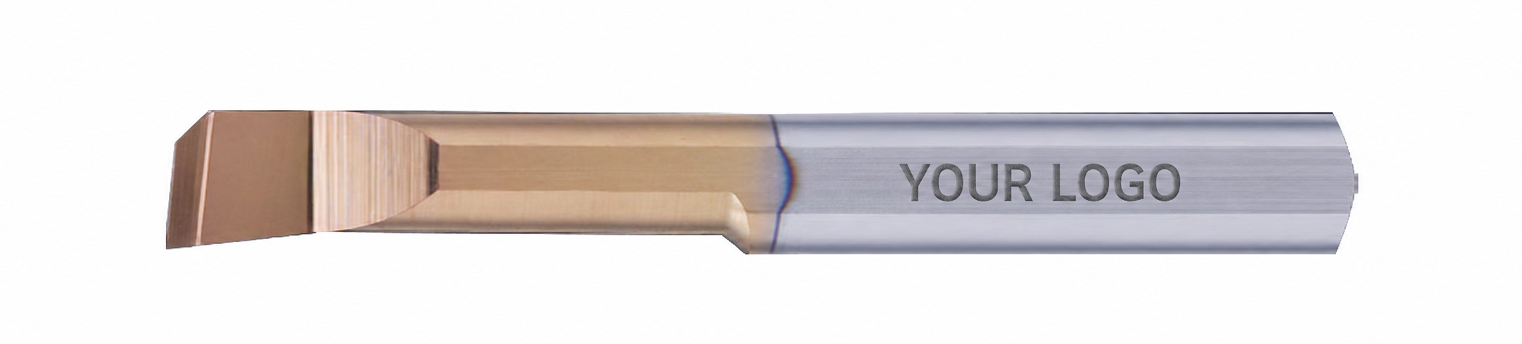
الوسم بالليزر
الشعارات ورموز الطرازات، حسب المساحة المتاحة على ساق المنتج.
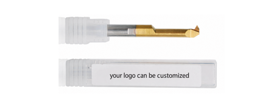
التغليف تحت العلامة التجارية الخاصة
الملصقات التي تحمل العلامة التجارية والتغليف الواقي.
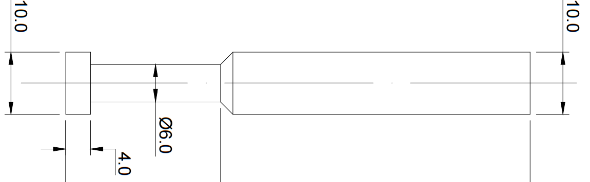
الرسومات والمواصفات
الأبعاد المعتمدة للطلبات المتكررة.
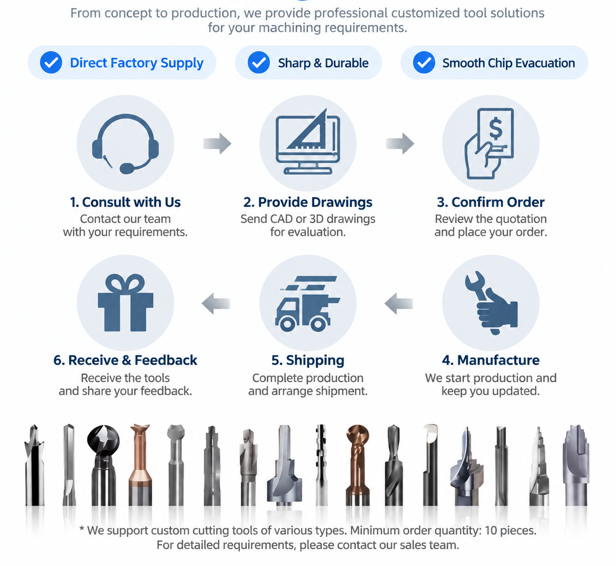
عملية الطلبات المخصصة
Requirement review → Drawing approval → Samples where required → Production & inspection.
MFR Grooving Bar Quality & Delivery
تُجرى عمليات فحص المواد ومراقبة عملية الطحن والفحص النهائي للتأكد من MFR face grooving bars وفقًا للمواصفات المؤكدة أو الرسومات المعتمدة.
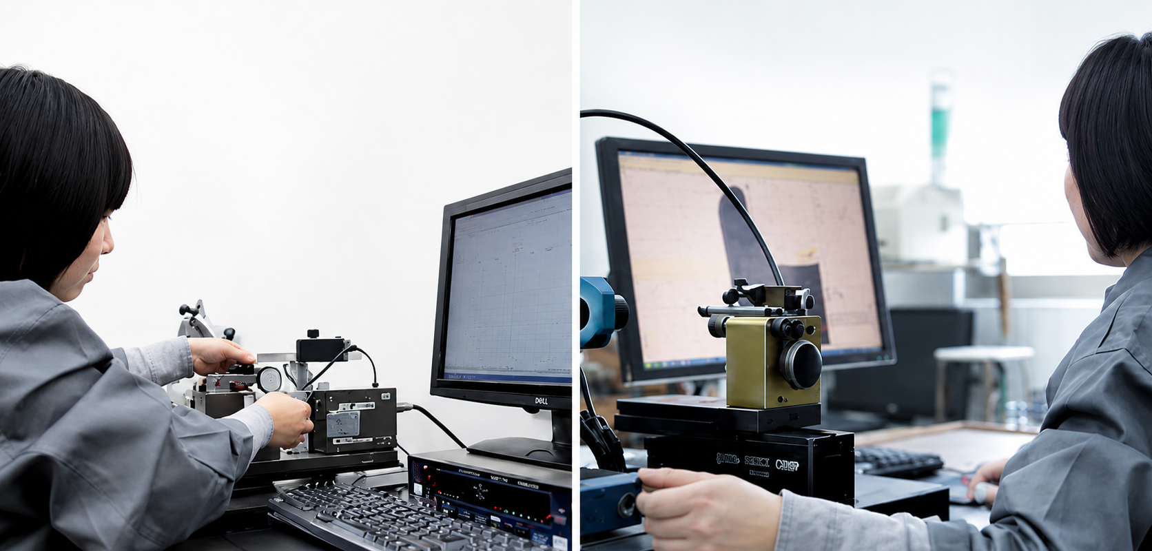
نقاط الفحص الرئيسية
- المادة: درجة الكربيد ومواصفات القطع الخام.
- الهندسة: Cutting width, depth, corner profile and edge condition.
- الأبعاد: Working length, shank size and overall length.
- التعريف: Model, marking and packaging labels.
Batch-record requirements are confirmed with the order.
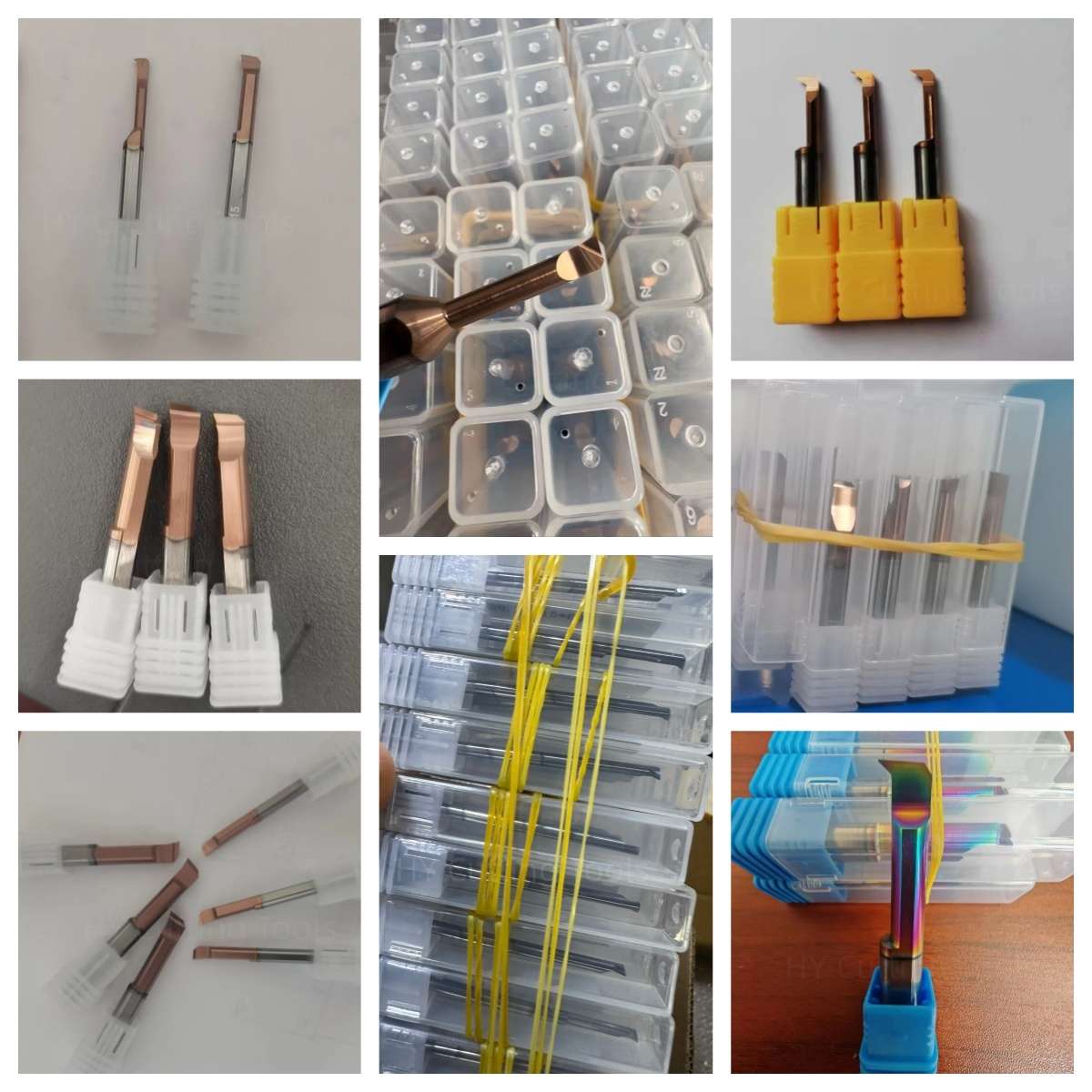
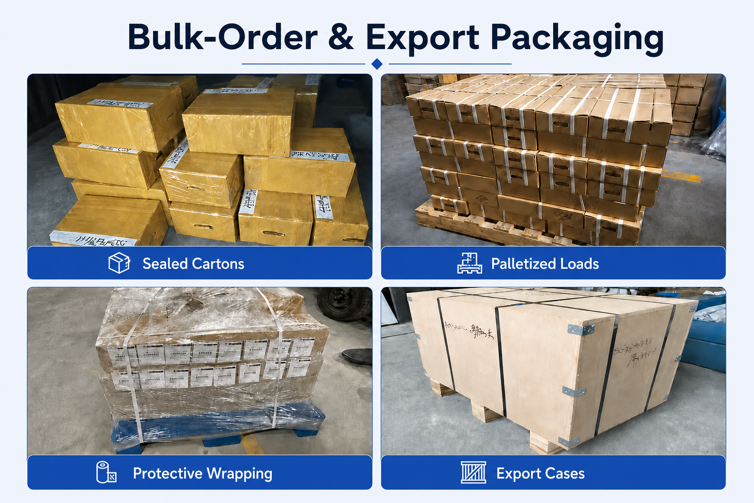
Tool Protection & Export Packing
Individual protection, clear labels and outer packing help protect cutting edges during storage and transport.

مدة التسليم والشحن
الأدوات القياسية: عادةً ما يستغرق الأمر من يوم إلى ثلاثة أيام عمل، حسب توفر المخزون.
الأدوات المخصصة: Lead time confirmed by geometry, coating, quantity and production requirements.

MFR Micro Face Grooving Bar FAQs
Is MFR suitable for face grooves inside small bores?
Which MFR shank size fits my bore diameter?
The listed minimum bores are Ø5 mm for Ø4 shanks, Ø6 mm for Ø5 shanks, Ø8 mm for Ø6 shanks and Ø10 mm for Ø8 shanks.
Also confirm groove diameters, head clearance and the complete entry and retraction path. Minimum bore size alone does not establish suitability.
What groove widths and cutting depths are available?
How do I choose the correct working length?
Can MFR grooving bars machine stainless steel or aluminum?
Custom Orders & Supply
Can I order custom widths, reach or OEM packaging?
What is the MOQ, and can I mix MFR models?
What should I send for pricing and delivery confirmation?
Selection & Technical Resources
هل تحتاج إلى معلومات عن المقاسات أو الأسعار أو الخيارات المخصصة؟
يرجى إرسال المواصفات والكمية المطلوبة للحصول على عرض أسعار.
- الأحجام القياسية
- طلبات تجريبية صغيرة
- أحجام متنوعة
- التصنيع حسب الطلب (OEM) والمنتجات المخصصة
عرض رمز الاستجابة السريعة – اتصل بقسم المبيعات عبر تطبيق WeChat

امسح الرمز ضوئيًا للتواصل معنا عبر تطبيق WeChat.
ويشات
امسح الرمز ضوئيًا للتواصل معنا عبر تطبيق WeChat.