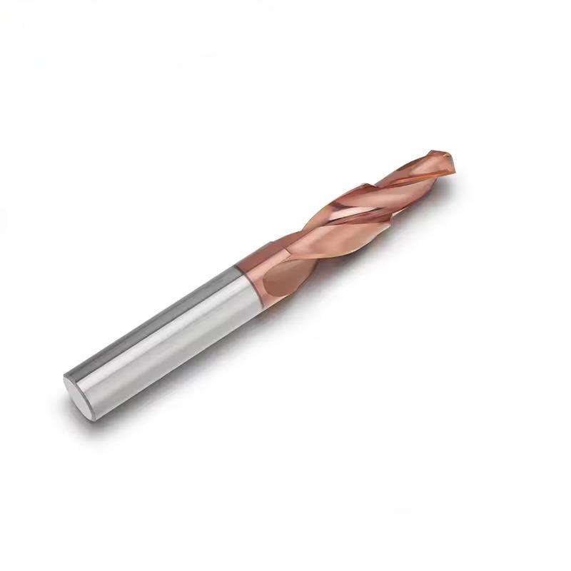
DLC-Coated 2-Flute Solid Carbide Flat-Bottom Step Drill for Aluminum
Consistent Quality
Consistent geometry across repeat orders.
Pedidos flexíveis
Small batches and mixed sizes available.
OEM Support
Custom marking, labels and packaging.
Padrão e personalizado
Standard sizes and custom configurations.
DLC-CoatedCarbide Step Drill
This DLC-coated 2-flute solid carbide flat-bottom step drill is designed to create a pilot feature and a larger flat-bottom stepped seat in one CNC machining cycle. The solid carbide body supports cutting rigidity, while the two-flute geometry provides chip space for aluminum and other suitable non-ferrous materials. Its low-friction DLC coating helps reduce aluminum adhesion and built-up edge. The tool is suitable for flat-bottom counterbores, recessed screw seats, shallow stepped holes and related precision hole-making operations where a conventional pointed drill would leave a conical bottom.
Flat-Bottom Step
2 Flutes
DLC
Alumínio
One Tool for a Stepped Flat-Bottom Hole
1
Pilot Section Starts the Hole
The smaller cutting section establishes the hole location and creates the initial diameter.
2
Step Edge Opens the Seat
The larger cutting section forms the stepped diameter or counterbore around the pilot feature.
3
Flat Shoulder Finishes the Bottom
The flat-bottom geometry produces a controlled seating surface instead of a conventional conical drill bottom.
Key Product Advantages
Flat-Bottom Seat Formation
Creates a controlled flat shoulder for recessed fasteners, counterbores and stepped-hole features.
Two Diameters in One Tool
Combines the pilot diameter and larger step diameter to reduce separate machining operations.
Low-Friction DLC Surface
Helps reduce aluminum adhesion, built-up edge and chip welding at the cutting edges.
Two-Flute Chip Space
Provides suitable chip space for aluminum while maintaining balanced two-edge cutting.
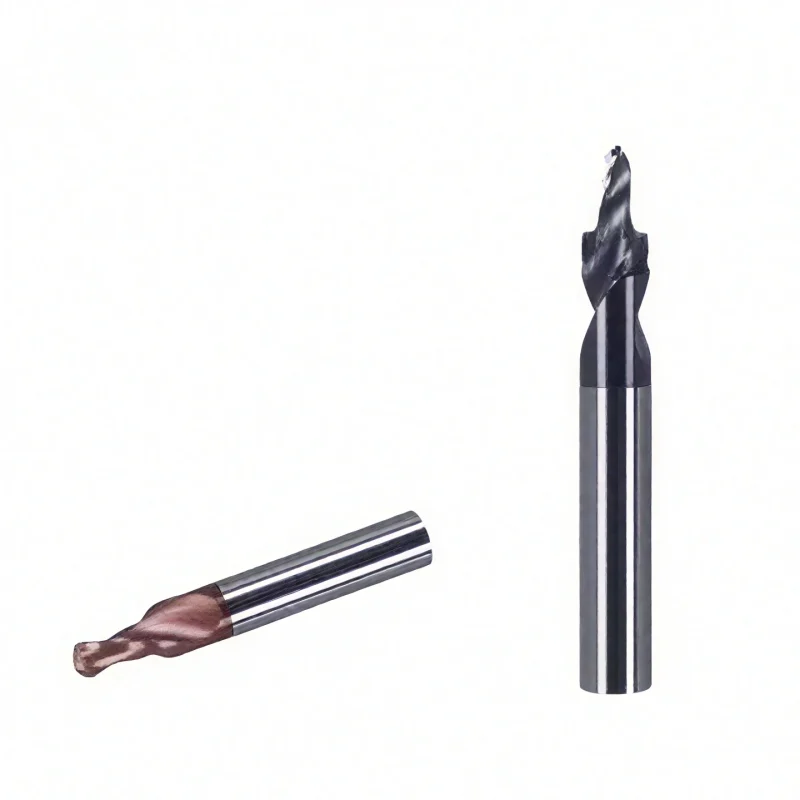
Product & Machining Demonstration
View the DLC-coated flat-bottom step-drill configuration, cutting edges and physical tool details for aluminum hole machining.
Why DLC Coating for Aluminum?
The DLC coating and aluminum-focused cutting geometry work together to address common non-ferrous machining challenges.
| ALUMINUM-MACHINING CHALLENGE | HOW DLC HELPS | PROCESS BENEFIT |
|---|---|---|
| Built-up edge and aluminum adhesion | The low-friction surface reduces the tendency of aluminum to stick. | Cleaner cutting edges and more stable dimensions |
| Chip welding around the compact step | Reduced sliding friction supports smoother chip movement. | Lower risk of chip packing and recutting |
| Repeated production wear | The coating protects the precision-ground carbide cutting edge. | More consistent hole quality across production batches |
| Burrs around the stepped seat | Sharp two-flute geometry supports cutting instead of rubbing. | Cleaner shoulders and reduced secondary deburring |
Application Materials & Tool Features

Aluminum Sheet
Suitable for screw seats, shallow counterbores and stepped holes in aluminum plate or sheet components.
Aluminum Profiles
Supports stepped mounting holes and recessed fastener features in suitable extruded profiles.
Copper Materials
Selected copper grades can be reviewed when the geometry, lubrication and chip-control conditions are suitable.
Acrylic & Selected Plastics
Application suitability should be confirmed according to brittleness, heat sensitivity and the required edge quality.
Applications & Target Scope
- Flat-bottom counterbores in aluminum components
- Recessed screw and fastener seats
- Pilot holes combined with a larger stepped diameter
- Shallow flat-bottom stepped holes
- Selected spot-facing and seating-surface operations
- Drawing-based custom stepped-hole geometries
Product Series Information
Reference configuration and application information for DLC-coated 2-flute solid carbide flat-bottom step drills for aluminum.
| Tipo de ferramenta | Flat-Bottom Step Drill |
| Substrato | Fine-Grain Solid Carbide |
| Contagem de flautas | 2 Flutes |
| Revestimento | DLC Coating |
| Cutting Form | Pilot Diameter + Larger Flat-Bottom Step |
| Primary Workpiece | Aluminum and Aluminum Alloys |
| Additional Materials | Selected Copper Grades, Acrylic and Plastics After Application Review |
| Standard Shank | Ø8 mm for the Listed Configurations |
| Standard Overall Length | 80 mm for the Listed Configurations |
| Personalização | Diameters, Step Depth, Lengths, Shank, Tolerance, Edge Geometry and Marking |
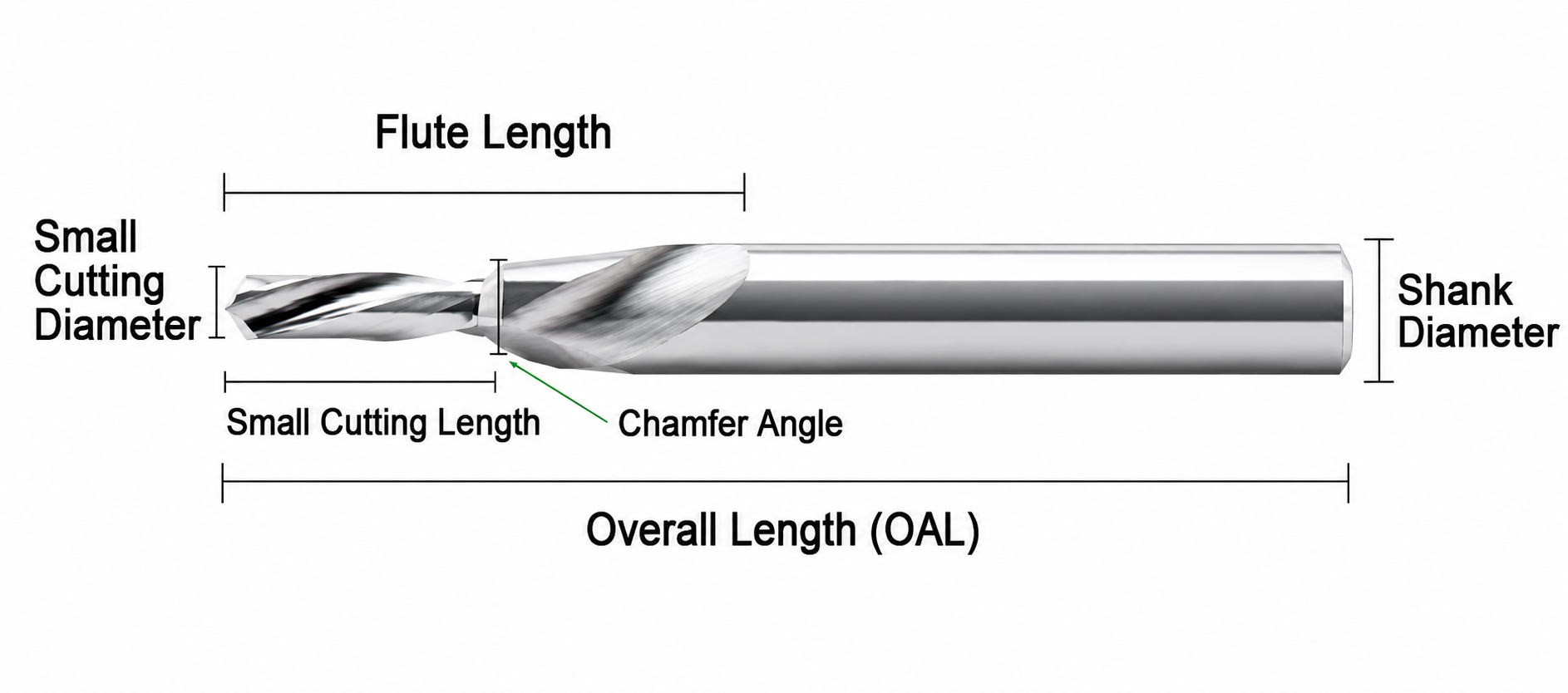
Tool Nomenclature & Dimension Reference
Confirm both step diameters and the required flat-bottom geometry against the workpiece drawing before ordering.
Standard Size Matrix
Reference dimensions transcribed from the supplied product information. All dimensions are in millimeters.
| Modelo | Cutting Diameter D | Cutting Length l | Shank Diameter d | Overall Length L |
|---|---|---|---|---|
| 4.1 × 6 × D8 × 80L | 4.1 | 6 | 8 | 80 |
| 4.2 × 5 × D8 × 80L | 4.2 | 5 | 8 | 80 |
| 4.5 × 5 × D8 × 80L | 4.5 | 5 | 8 | 80 |
| 5.0 × 5 × D8 × 80L | 5.0 | 5 | 8 | 80 |
Machining Recommendations
General setup and application guidance for stable flat-bottom step drilling in aluminum.
Information Required for Custom Step Drills
- Pilot Feature: Small diameter, pilot length and bottom condition
- Step Feature: Large diameter, step depth and shoulder profile
- Tool Dimensions: Flute length, overall length and shank diameter
- Workpiece: Aluminum grade, hole type and machining conditions
- Quality Requirements: Dimensional tolerances, surface finish and inspection points
- Order Information: Required quantity, marking and packaging requirements
Recommended Starting Cutting Parameters
Starting values should be adjusted according to the exact aluminum alloy, step geometry, machine rigidity, coolant method and required surface finish.
Solid Carbide Drill Cutting Data Guide
Access starting speeds and feeds for product selection and application testing.
Flat-Bottom Step Drill Customization
Custom pilot diameters, step diameters, flat-bottom profiles, cutting lengths, DLC coating and dimensional tolerances are engineered according to the aluminum grade, required hole geometry and machining conditions.
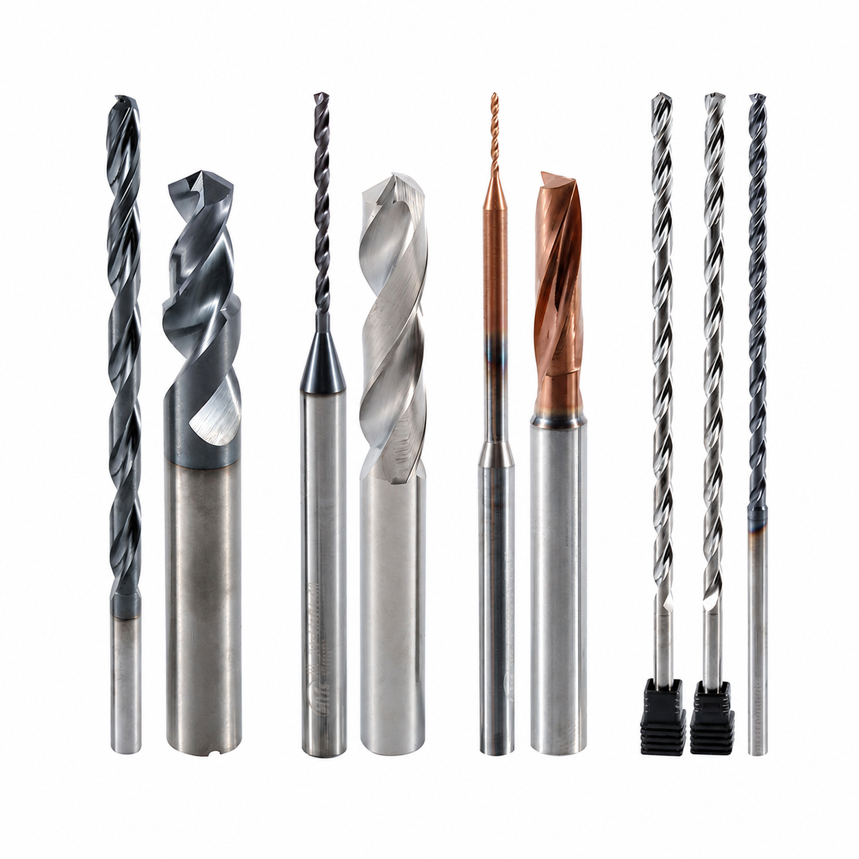
Custom Geometry & Edge Preparation
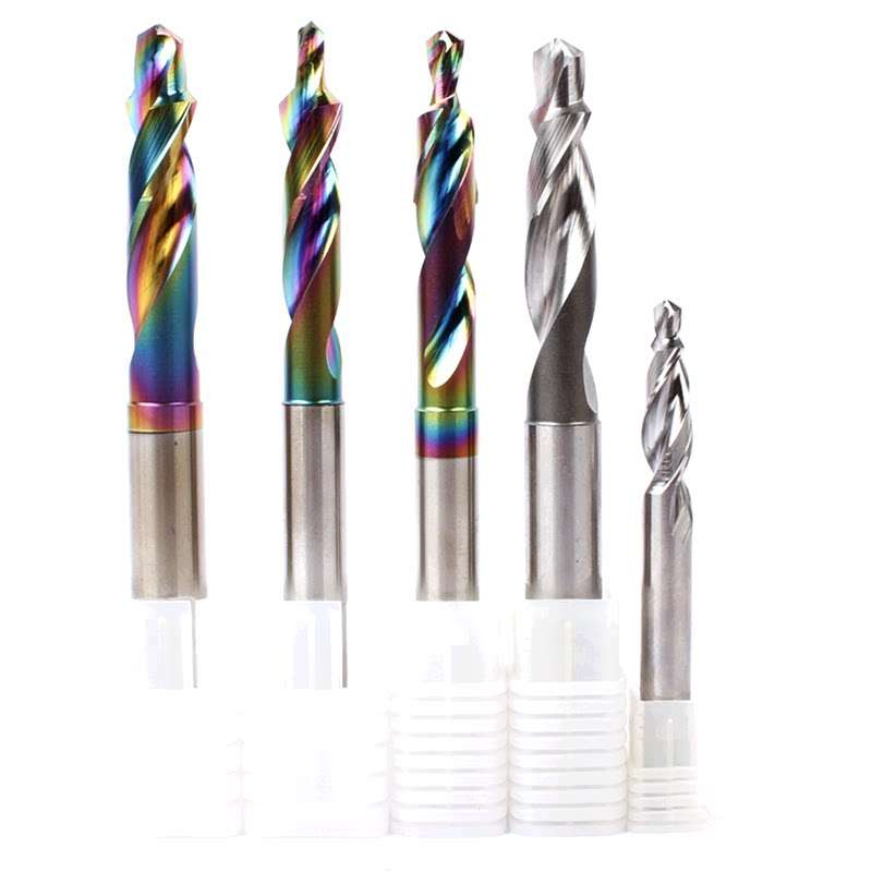
Drawing-based pilot diameters, step diameters, step depths, flat shoulders, corner forms and cutting-edge preparation optimized for aluminum chip control.
Dimensions & Reach Options
Pilot length, step depth, flute length, overall length and shank dimensions can be configured around the required flat-bottom stepped-hole profile.
Serviços de OEM e marca própria
OEM manufacturing and private-label supply options for industrial distributors, tooling brands and aluminum-machining customers.
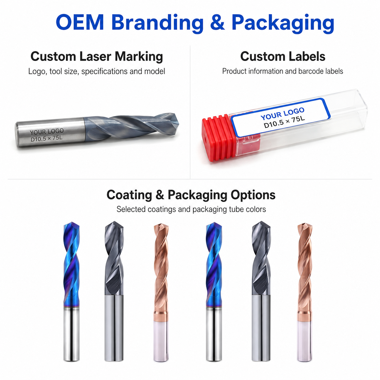
Laser Etching
High-precision laser marking for logos, tool codes, model numbers, diameter specifications and batch identification.
Custom Packaging
Single plastic tubes, multi-pack boxes, specialized inserts, custom labels and private-label color selections.
Commercial Terms
Flexible MOQ options for standard sizes, custom step geometries, trial orders and scheduled repeat supply.
Technical Workflow
Inquiry
Submit the hole drawing, aluminum grade, tolerance and required quantity.
Engineering
Step geometry, dimensions, coating and application requirements are reviewed.
Commercial
Quotation approval, pricing, MOQ and production lead time are confirmed.
Production
Carbide grinding, flat-bottom step formation, edge preparation and DLC coating.
Quality Control
Dimension inspection, step-profile verification, packaging and dispatch.
Inspection & Quality Control
Drill dimensions, cutting-edge geometry and visible surface condition are checked according to the confirmed product specification and application requirements.

Protective Packing for Shipment
Finished drills are protected individually before batch labeling and export-carton reinforcement.

Individual Tool Protection
Each drill is individually protected in a plastic tube to reduce contact damage during storage, handling and transportation.
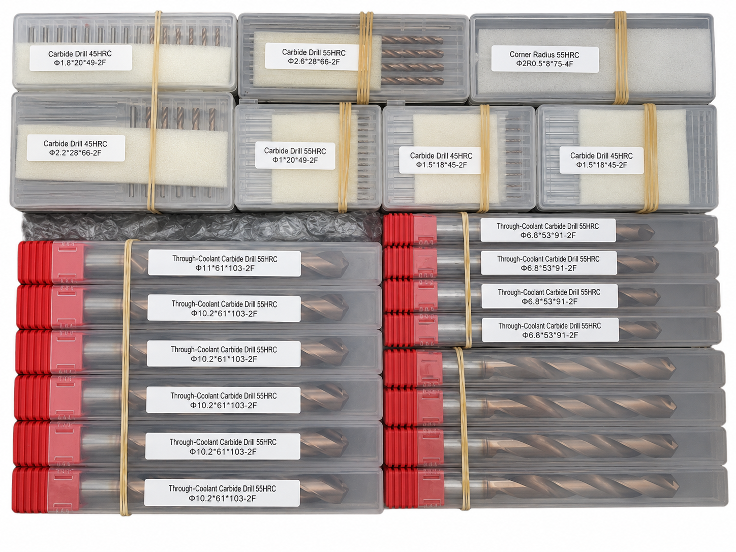
Batch & Label Verification
Tools are grouped and labeled by specification to support order verification before carton packing.

Export Carton Protection
Batch packaging, cushioning materials and reinforced export cartons are selected according to the order quantity and shipping method.
Reference Lead Time
The following timeframes are general references. Availability and production scheduling are reviewed for each order.
Shipping Options
Shipping arrangements can be selected according to order size, delivery schedule and destination.

Product FAQs
Product-specific information about applications, step geometry, DLC coating, available configurations and machining requirements for this solid carbide flat-bottom step drill.
What materials is this flat-bottom step drill designed for?
This drill is primarily designed for aluminum and selected non-ferrous materials. Final suitability should be confirmed according to the exact alloy, silicon content, hole geometry, cutting depth and machining conditions.
What machining operations can the step geometry perform?
The two-diameter geometry can produce a pilot hole and a larger stepped feature in one machining cycle. It is suitable for selected stepped holes, clearance features, counterbores and drawing-specific precision hole profiles.
What is the advantage of the flat-bottom geometry?
The flat-bottom cutting geometry is intended to form a controlled hole-bottom or counterbore profile without leaving the conventional conical bottom produced by a standard twist drill. Machine rigidity and correct entry conditions remain important for stable machining.
Why is DLC coating suitable for aluminum machining?
DLC coating provides a low-friction cutting surface that helps reduce aluminum adhesion and built-up edge. Together with the two-flute geometry, it supports smoother chip flow and more stable surface quality under suitable cutting conditions.
Can the step dimensions and tool geometry be customized?
Yes. The small diameter, large diameter, step length, flute length, overall length, shank diameter, dimensional tolerances and selected cutting-edge details can be reviewed according to your drawing and application requirements.
What information is required for a quotation?
Please provide the small and large diameters, step length, flute length, overall length, shank diameter, workpiece material, hole type, dimensional tolerances and estimated quantity. A technical drawing is recommended for custom step-drill requirements.
Ordering & OEM FAQs
General information for trial orders, drawing-based production, private labeling and repeat purchasing.
Do you accept small trial orders?
Yes. Small sample or trial orders are welcomed for dimensional verification and machining evaluation before committing to volume purchasing.
Can you manufacture the drill according to our drawing?
Yes. Drawing-based production is available for non-standard diameters, step positions, lengths, tolerances and cutting geometries. The drawing is reviewed before production to confirm manufacturability and inspection requirements.
Is OEM laser marking available?
Yes. Custom shank laser marking such as a logo, model number, dimensions or batch identification can be reviewed together with OEM labels and packaging requirements.
Can approved specifications be repeated for future orders?
Yes. Confirmed dimensions, geometry, coating, marking and packaging requirements can be recorded to support consistent repeat production. The final delivery schedule is confirmed according to specification, quantity and current production capacity.
Downloads & Technical Resources
Access product dimensions, series information and starting cutting data for product selection and application review.
Need Sizes, Pricing or Custom Options?
Send us the required tool type, sizes, quantities, workpiece material and any OEM or custom requirements. We will confirm suitable specifications, availability, lead time and quotation details.
Drawings, size lists and reference photos are welcome.