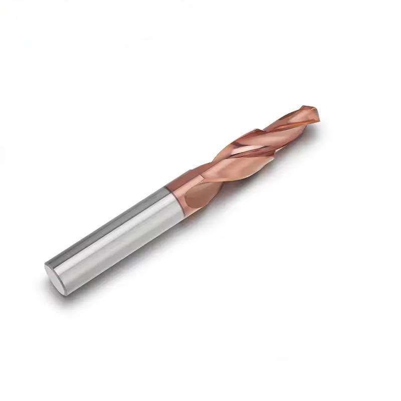
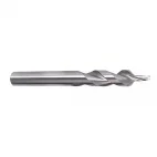
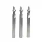
Custom Solid Carbide Step Drill for Multi-Diameter Hole Machining
Consistent Quality
Consistent geometry across repeat orders.
Pedidos flexíveis
Small batches and mixed sizes available.
OEM Support
Custom marking, labels and packaging.
Padrão e personalizado
Standard sizes and custom configurations.
Custom Solid Carbide Step Drill Overview
This custom solid carbide step drill is developed around the required finished hole rather than a fixed catalog size. Multiple diameters, step depths, shoulders, chamfers and pilot features can be combined into one tool to reduce separate machining operations and support consistent alignment between related hole features. Each design is reviewed according to the workpiece material, hole drawing, machine capability, coolant method, production volume and required surface finish. Geometry, carbide grade, edge preparation, coating and dimensional tolerances are finalized on the approved tool drawing.
Custom Step Drill
Multi-Diameter
Carbeto sólido
Drawing Based
Application-Specific Combination Tool Example
The illustrated tool is one example of a custom solid carbide step and compression geometry for composite-material machining.
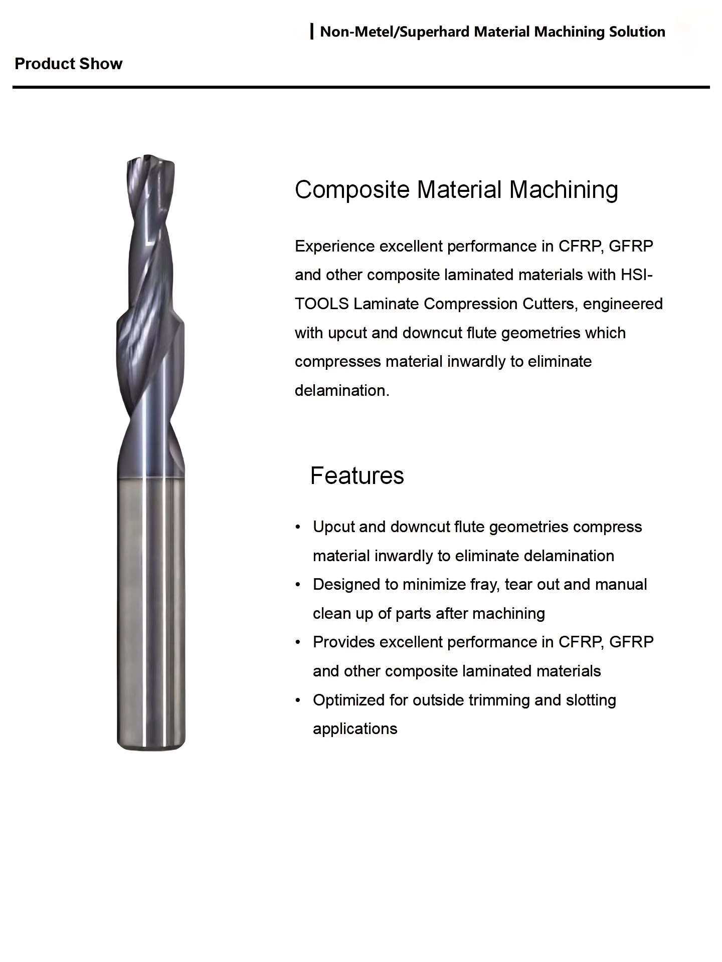
Upcut and downcut compression geometry, step diameters and cutting lengths can be engineered around the component and workpiece material. Final tool construction is subject to engineering review and drawing approval.
Key Product Advantages
Multiple Features in One Tool
Combines pilot, clearance, counterbore, shoulder and chamfer features in one sequence.
Consistent Diameter Alignment
Related diameters are ground on one carbide body to support concentricity.
Material-Matched Geometry
Point form, flute direction, edge preparation and coating match the workpiece.
Controlled Repeat Production
Approved drawings and tool identification support consistent repeat orders.
Why Use a Custom Step Drill?
| PRODUCTION CHALLENGE | CUSTOM TOOL RESPONSE | POTENTIAL PROCESS BENEFIT |
|---|---|---|
| Pilot drilling, counterboring and chamfering require separate tools | Combine selected diameters and transitions into one step drill | Fewer tool changes and a shorter machining sequence |
| Alignment between related hole features is difficult to maintain | Grind the related cutting features on one carbide body | More consistent alignment between diameters |
| Burrs, delamination or edge breakout occur in application-specific materials | Match the rake, flute direction, point style and edge preparation to the material | Cleaner entry, exit and shoulder formation |
| A standard tool does not match the component drawing | Define every diameter, step length, angle, shank and overall length to print | A tool designed around the actual finished feature |
Typical Custom Step-Drill Projects
Fastener & Seat Holes
Pilot, clearance diameter, counterbore and chamfer combined in one setup.
Composite Laminates
Application-specific geometry for CFRP, GFRP, G10, fiberglass and selected filled plastics.
Bushing & Alignment Features
Related diameters machined from one tool body for consistent feature alignment.
Combination Drilling
Production applications where fewer tool changes can support stable cycle time and process control.
From Hole Drawing to Finished Tool
STAGE 01
Requirements
Submit the drawing, material and production target.
STAGE 02
Engineering
Review geometry, coating and inspection needs.
STAGE 03
Approval
Confirm dimensions and tool construction.
STAGE 04
Manufacturing
Grinding, edge preparation and coating.
STAGE 05
Inspection
Verify agreed features before delivery.
Product Video
View the custom solid carbide step-drill configuration and physical cutting geometry.
Product Series Information
General configuration framework for drawing-based custom solid carbide step drills used in multi-diameter hole machining.
| Tipo de ferramenta | Custom Solid Carbide Step Drill |
| Tool Construction | One-Piece Solid Carbide |
| Diameter Configuration | Two-Diameter and Selected Multi-Step Profiles |
| Geometria | Drawing-Defined Point, Shoulder, Chamfer, Radius or Flat-Bottom Features |
| Configuração da flauta | Application-Specific Flute Count, Helix Direction, Chip Space and Edge Preparation |
| Haste | Straight, Reduced or Drawing-Defined Cylindrical Shank |
| Revestimento | Selected According to Workpiece Material and Wear Mechanism |
| Método de resfriamento | External or Internal Coolant Where Tool Geometry Permits |
| Tolerância | Defined and Confirmed on the Approved Tool Drawing |
| Primary Supply Method | Drawing-Based Custom Manufacturing |
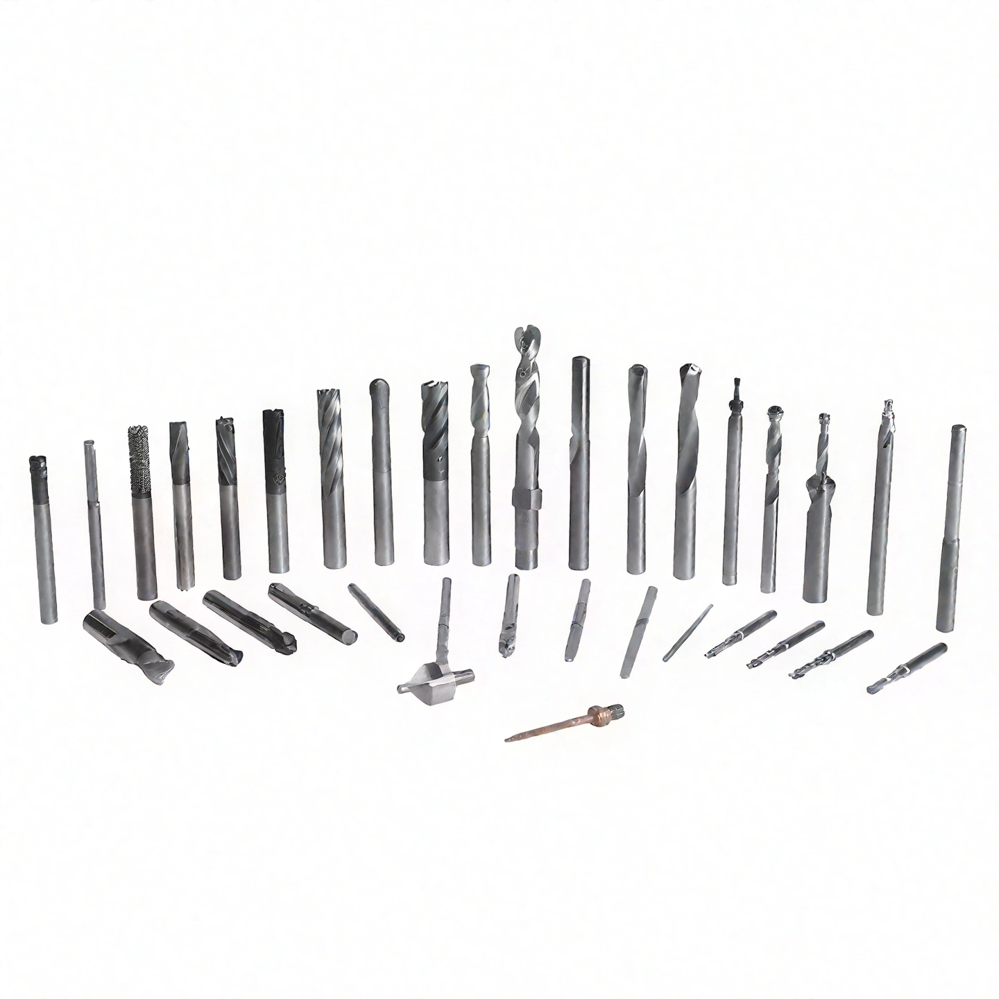
Reference Geometry & Size Examples
The illustrated models show reference examples of non-standard step and combination-tool configurations.
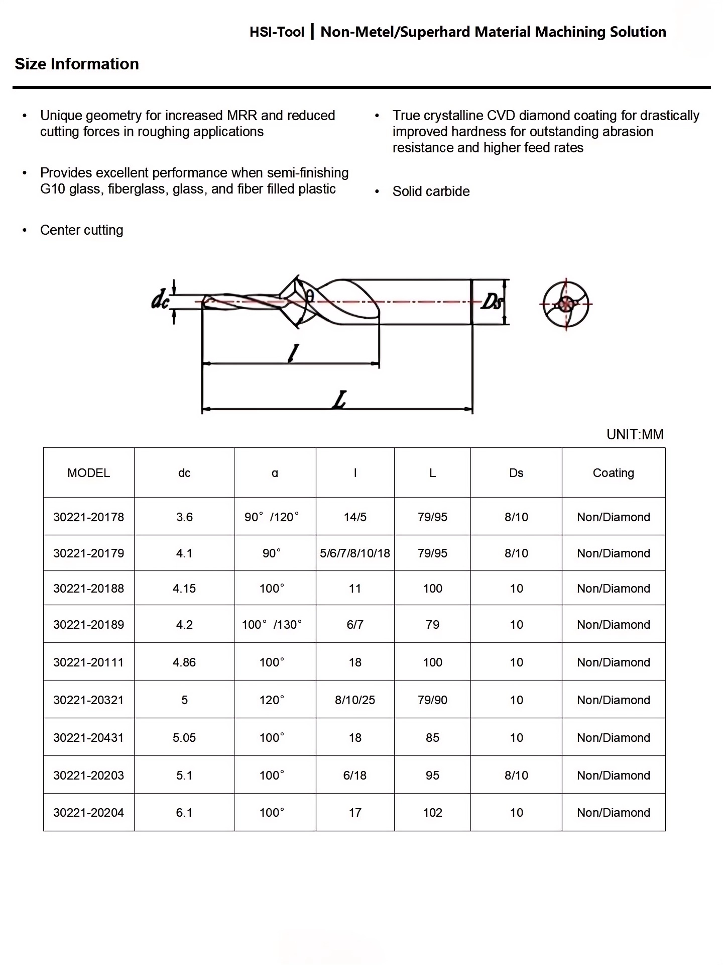
The illustrated dimensions and models are reference examples for non-metal and abrasive-material tooling. Production tools may use different diameters, angles, cutting lengths, shank dimensions and coatings according to the approved drawing.
Custom Configuration Matrix
Available features are reviewed according to diameter, tool strength, machining conditions and inspection requirements.
| PARAMETER | CONFIGURATION OPTIONS |
|---|---|
| Hole Geometry | D1/D2/D3 diameters, step depths, shoulder widths, pilot lengths and blind- or through-hole configurations |
| Point & Transition Form | Point angle, flat or center-cutting end, drawing-defined transitions, chamfers, radii and corner forms |
| Geometria da flauta | Flute count, helix direction, chip space, compression-style geometry, margin design and edge preparation |
| Carbide & Coating | Carbide grade and coating selected according to workpiece material, abrasiveness, temperature and adhesion tendency |
| Shank & Overall Length | Straight or reduced shank, shank diameter, clamping length, reach, neck clearance and overall tool length |
| Coolant Delivery | External coolant or internal coolant channels where diameter, length and tool geometry permit |
| Identification | Laser marking, tool numbers, drawing revisions, private labels and custom packaging |
Information Required for an Accurate Quotation
Hole Drawing
- Every diameter and tolerance
- Each step depth and shoulder form
- Point, chamfer, radius or flat-bottom requirement
- Through-hole or blind-hole condition
Peça de trabalho
- Exact material grade and hardness
- Solid, laminated, stacked or interrupted condition
- Entry and exit surface conditions
- Required finish and burr control
Machining Setup
- CNC machine and spindle interface
- Holder and maximum allowable length
- Coolant or dust-extraction method
- Current process, cycle target and order quantity
Design Confirmation & Quality Control
Custom tools are controlled by an agreed drawing rather than a generic product-size table.
Custom Multi-Diameter Step Drill Configuration
Multiple cutting diameters, step positions, shoulder profiles, tool lengths, coatings and dimensional tolerances are configured according to the component drawing, workpiece material and required hole-making process.
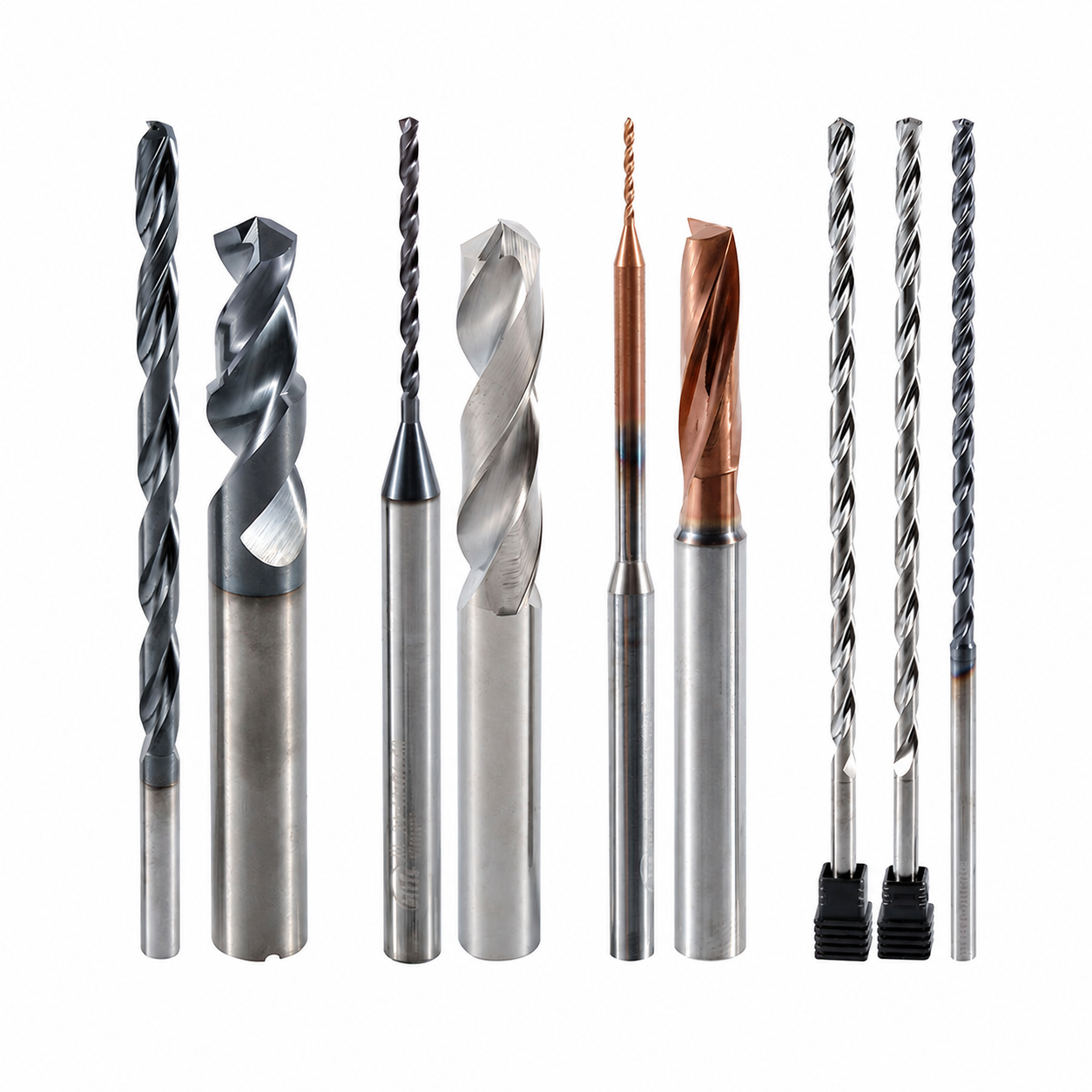
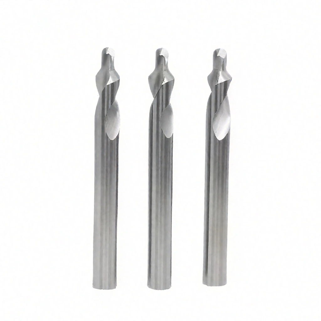
Custom Step Geometry & Edge Preparation
Two-diameter and selected multi-step geometries can combine pilot holes, clearance diameters, counterbores, chamfers and drawing-defined transitions in one tool.
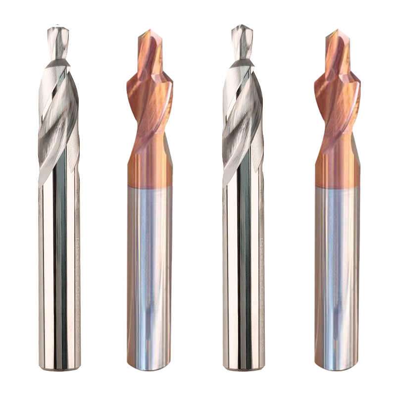
Dimensions & Step-Position Options
Each cutting diameter, step position, step length, flute length, overall length and shank dimension can be configured around the required multi-diameter hole profile.
Serviços de OEM e marca própria
Drawing-based manufacturing and private-label supply options for industrial distributors, tooling brands and repeat-production customers.
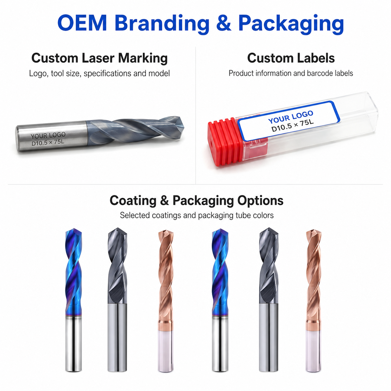
Laser Etching
Custom laser marking for logos, tool codes, drawing numbers, diameter specifications and batch identification.
Custom Packaging
Individual protective tubes, custom labels, multi-pack boxes, specialized inserts and private-label packaging.
Commercial Terms
Flexible MOQ options for prototype tools, trial batches, repeat orders and scheduled supply programs.
Technical Workflow
Inquiry
Submit the drawing, workpiece material, tolerances and required quantity.
Engineering
Diameter transitions, step positions, geometry and coating are reviewed.
Commercial
Quotation, MOQ, production schedule and delivery terms are confirmed.
Production
CNC grinding, step formation, edge preparation, coating and marking.
Quality Control
Diameter, step position, profile and concentricity inspection before dispatch.
Inspection & Quality Control
Drill dimensions, cutting-edge geometry and visible surface condition are checked according to the confirmed product specification and application requirements.

Protective Packing for Shipment
Finished drills are protected individually before batch labeling and export-carton reinforcement.

Individual Tool Protection
Each drill is individually protected in a plastic tube to reduce contact damage during storage, handling and transportation.
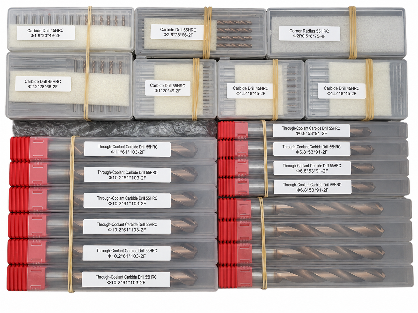
Batch & Label Verification
Tools are grouped and labeled by specification to support order verification before carton packing.

Export Carton Protection
Batch packaging, cushioning materials and reinforced export cartons are selected according to the order quantity and shipping method.
Reference Lead Time
The following timeframes are general references. Availability and production scheduling are reviewed for each order.
Shipping Options
Shipping arrangements can be selected according to order size, delivery schedule and destination.

Product FAQs
Product-specific information about multi-diameter hole machining, custom step geometry, available configurations and technical requirements for this solid carbide step drill.
What machining operations is this custom step drill designed for?
This tool is designed to machine two or more related hole diameters in one operation. It can be configured for stepped holes, pilot-and-clearance holes, counterbores, recessed fastener features and drawing-specific multi-diameter hole profiles.
What is the advantage of combining multiple diameters in one tool?
Combining multiple cutting diameters can reduce separate drilling and counterboring operations, shorten tool-change time and help maintain alignment between related hole features. The final benefit depends on the component geometry, machine rigidity and production setup.
How many step diameters can be combined?
Two-diameter and selected multi-step configurations can be reviewed. The practical number of steps depends on the diameter transitions, step lengths, overall tool rigidity, chip-evacuation space and required dimensional tolerances.
What workpiece materials can the step drill be designed for?
The substrate, cutting geometry, edge preparation and coating can be selected for steel, stainless steel, cast iron, aluminum and selected non-ferrous materials. Final suitability should be confirmed from the exact material grade, hardness and machining conditions.
Which dimensions and tool features can be customized?
The individual cutting diameters, step lengths, flute length, overall length, shank diameter, point geometry, shoulder form, corner transitions, dimensional tolerances, coolant configuration and coating can be reviewed according to the hole drawing.
What information is required for a quotation?
Please provide a hole or tool drawing showing every diameter, step length, flute length, overall length, shank size and tolerance. The workpiece material, hardness, hole type, machine setup, coolant method and estimated quantity should also be included.
Ordering & OEM FAQs
General information for drawing review, trial orders, repeat production, private labeling and production scheduling.
Can you manufacture the step drill according to our drawing?
Yes. Drawing-based production is available for non-standard diameters, multiple step positions, special lengths, shoulder forms and dimensional tolerances. The drawing is reviewed before production to confirm manufacturability and inspection requirements.
Do you accept small trial orders?
Yes. Small trial orders can be reviewed for dimensional verification and machining evaluation before volume purchasing. The applicable MOQ depends on the tool geometry, coating and production requirements.
Is OEM laser marking and custom packaging available?
Yes. Custom shank laser marking such as a logo, model number, dimensions or batch identification can be reviewed together with private-label tubes, labels, boxes and packaging requirements.
Can approved specifications be repeated for future orders?
Yes. Confirmed dimensions, geometry, coating, tolerances, marking and packaging requirements can be recorded to support controlled repeat production. The delivery schedule is confirmed according to specification, quantity and current production capacity.
Downloads & Technical Resources
Access product series information and starting cutting data for application review and custom-tool planning.
Need Sizes, Pricing or Custom Options?
Send us the required tool type, sizes, quantities, workpiece material and any OEM or custom requirements. We will confirm suitable specifications, availability, lead time and quotation details.
Drawings, size lists and reference photos are welcome.