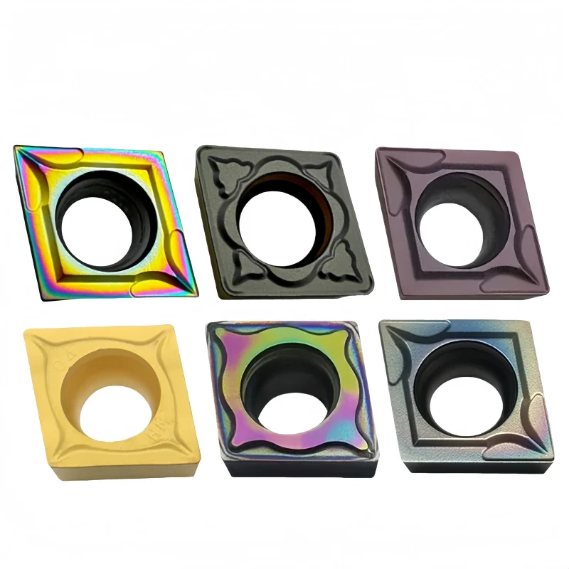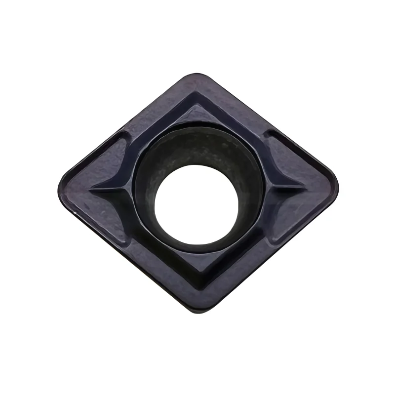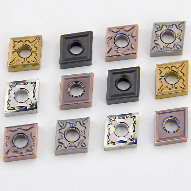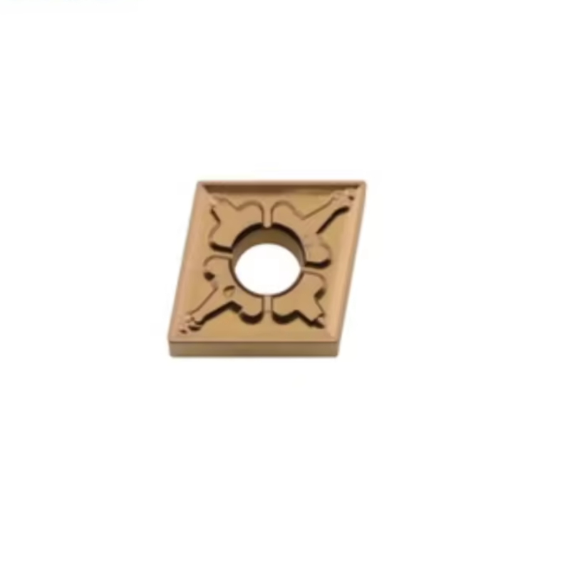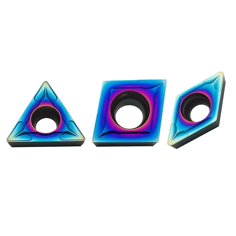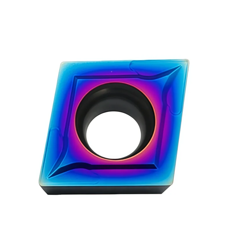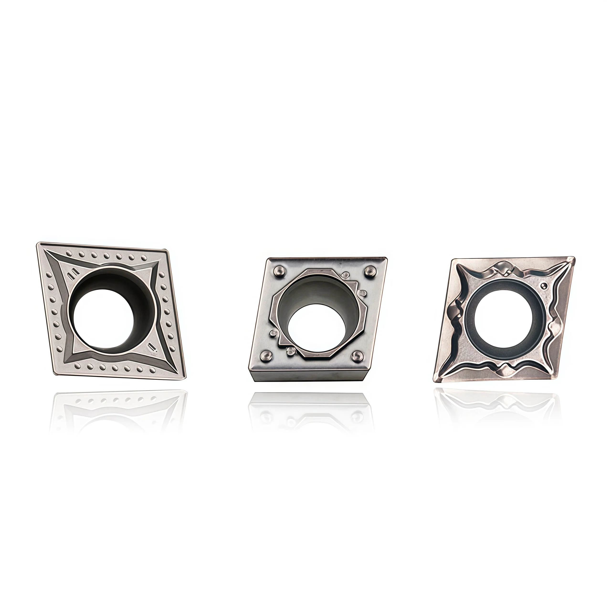


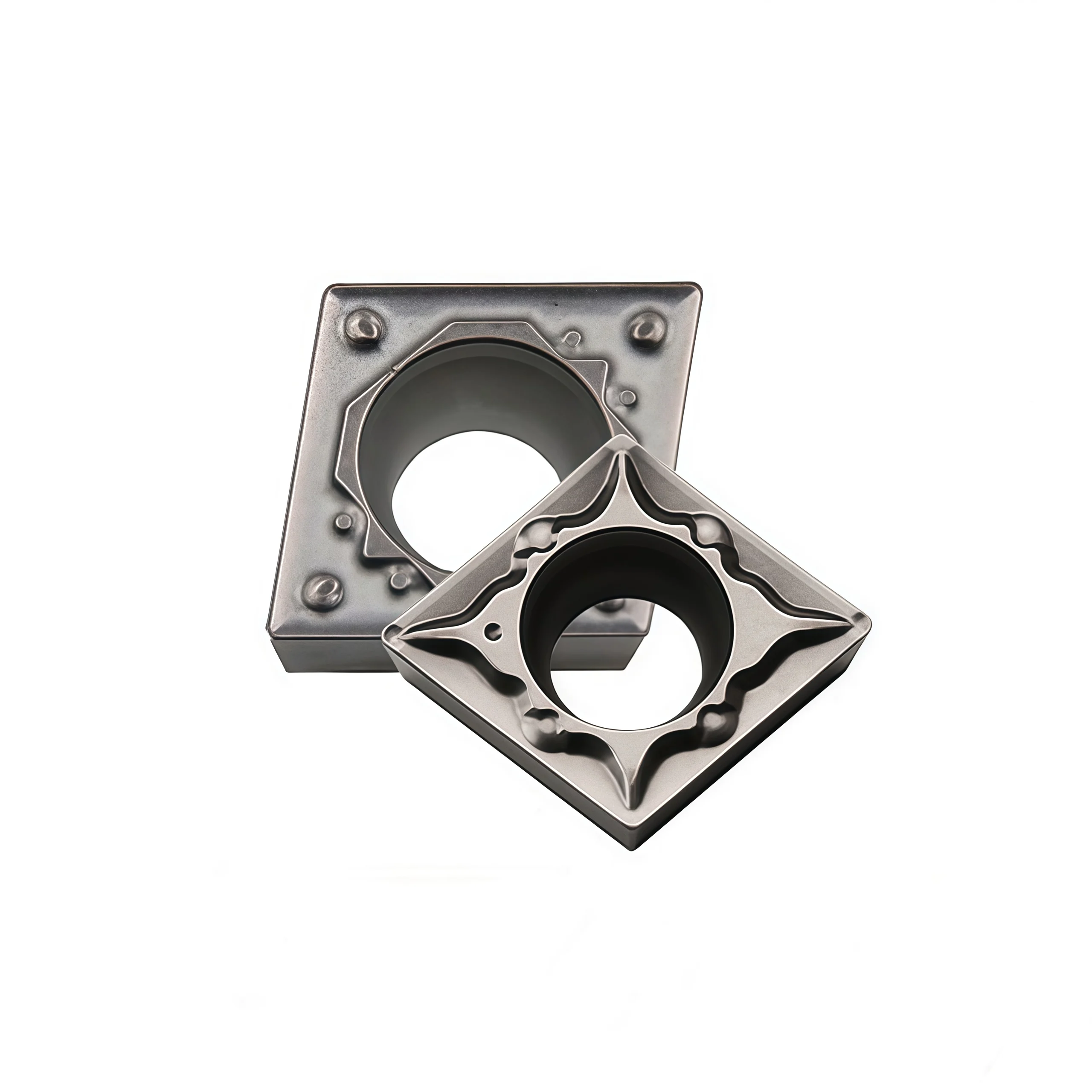


CCMT 09T304/09T308 FG Cermet Turning Inserts for Steel Finishing
CCMT09T304 and CCMT09T308 FG cermet inserts are intended for stable steel finishing and semi-finishing. The positive 80° geometry and finishing chipbreaker support low cutting resistance, controlled chips and consistent surface quality, making the series suitable for distributors serving precision CNC turning customers.
Consistent Quality
Consistent geometry across repeat orders.
Flexible Orders
Small batches and mixed sizes available.
OEM Support
Custom marking, labels and packaging.
Standard & Custom
Standard sizes and custom configurations.
Product Overview
The CCMT09T308 / CCMT09T304 FG Cermet CNC Turning Inserts are engineered for high-efficiency semi-finishing and finishing operations on carbon steel, alloy steel, and low-hardness stainless steel. Manufactured with a premium titanium-based cermet substrate and precision-ground cutting edges, these inserts provide excellent wear resistance, high temperature stability, and consistent machining performance under continuous cutting conditions.
Compliant with ISO standards, the CCMT09T3 series fits a wide range of toolholders, making it a reliable and cost-effective choice for high-speed CNC turning applications.
Key Features
-
Premium Titanium-Based Cermet Substrate
Exceptional wear resistance, low friction coefficient, and high thermal stability. -
Sharp Cutting Edge
Ideal for semi-finishing and finishing, ensuring reduced cutting forces and improved surface finish. -
Optimized Chip Breaker
Ensures smooth chip control and prevents chip entanglement. -
Anti Built-Up Edge (Anti-BUE)
Reduces welding and adhesion, ensuring stable dimensional accuracy. -
High-Speed Machining Capability
Maintains edge stability even at high cutting speeds. -
ISO Standard Compatibility
Fits standard CCMT toolholders for easy replacement and versatility.
Suitable Materials
| Material Type | Performance |
|---|---|
| Carbon Steel (C45 / 1045 / Q235) | Stable semi-finishing with excellent finish |
| Alloy Steel (42CrMo / SCM440) | High efficiency & long tool life |
| Low-Hardness Stainless Steel (201 / Some 304 applications) | Clean cutting, smooth surface |
| Free-Cutting & Pre-Hardened Steels | Extended durability |
Machining Applications
-
CNC automatic lathes
-
Mass production turning lines
-
Precision shaft machining
-
Automotive & motorcycle parts finishing
-
High-speed continuous machining
Advantages
-
Longer tool life due to superior cermet wear resistance
-
Mirror-level surface finish (Ra0.4–0.8 achievable)
-
Reduced tool change frequency, improving productivity
-
High precision edge geometry ensures consistent dimensions
-
Excellent for high-speed and continuous cuts, resisting thermal cracking and edge chipping
Technical Specifications
| Specification | CCMT09T308 FG | CCMT09T304 FG |
|---|---|---|
| ISO Model | CCMT 09T3 08 | CCMT 09T3 04 |
| Material | Titanium-Based Cermet | Titanium-Based Cermet |
| Nose Radius (Re) | 0.8 mm | 0.4 mm |
| Application | Semi-Finishing / Finishing | Finishing |
| Work Materials | Steel, Alloy Steel, Stainless Steel | Steel, Alloy Steel |
| Coating | Uncoated / Optional PVD | Uncoated / Optional PVD |
| Insert Shape | 80° Rhombic Insert | 80° Rhombic Insert |
| Parameter | Specification |
|---|---|
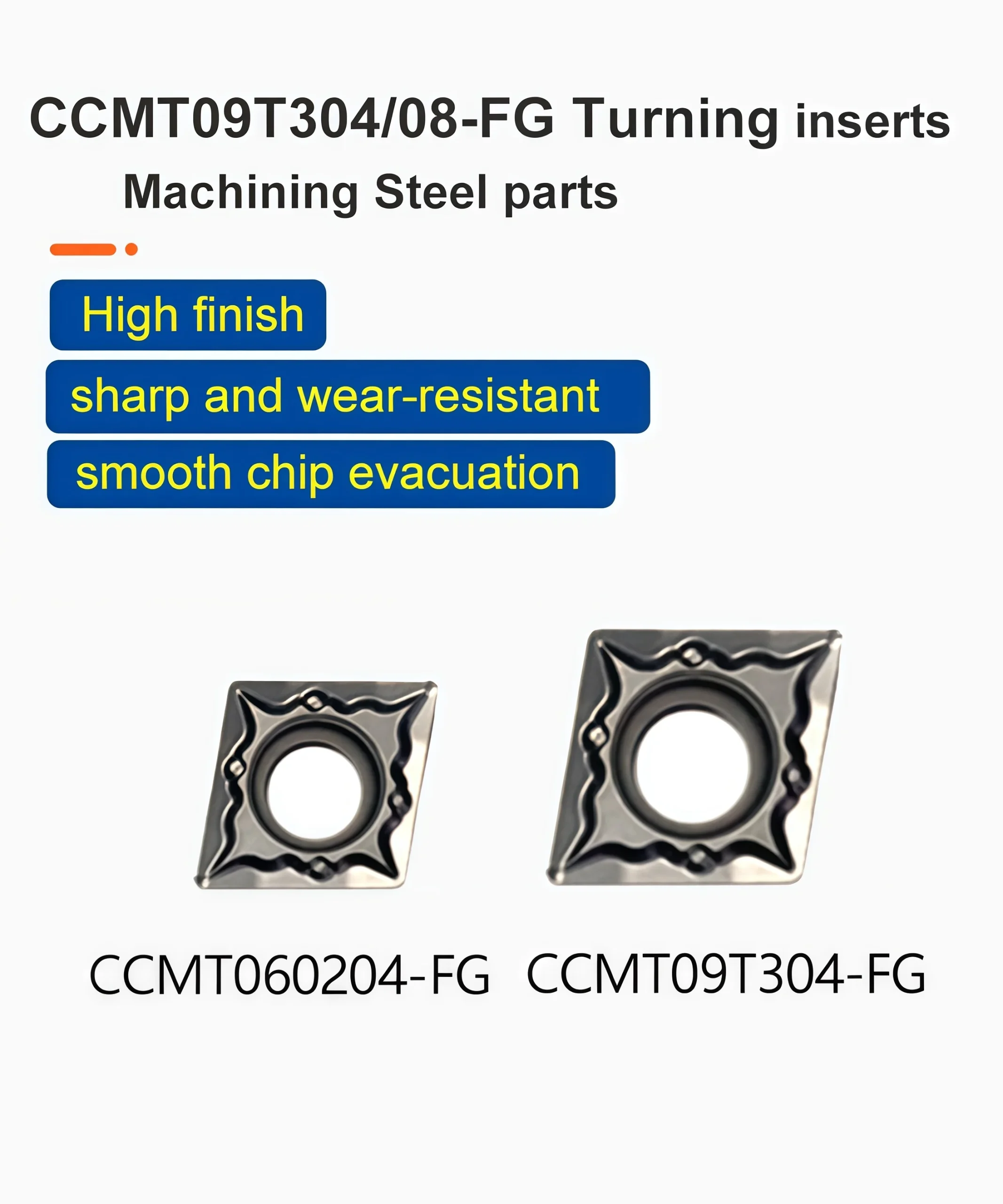
| Model | CCMT060204-FG, CCMT09T304/08-FG |
| Material | CERMET |
| Workpiece | aluminum/copper/steel/hardened steel/stainless steel/cast iron |
| Processing | Finishing, Semi-finishing and rough |
| Coating | no coating |
| Color | grey |
| MOQ Quantity | 10 pieces |
| Package | 10pcs / box |
Recommended Cutting Parameters (For Reference)
Machining Steel
-
Cutting speed (Vc): 120–220 m/min
-
Feed rate (F): 0.08–0.25 mm/rev
-
Depth of cut (Ap): 0.2–1.2 mm
Machining Alloy Steel
-
Cutting speed (Vc): 100–180 m/min
-
Feed rate (F): 0.06–0.2 mm/rev
-
Depth of cut (Ap): 0.1–1.0 mm



Size Chart & Specifications
The supplied FG dimension chart lists CCMT09T304-FG and CCMT09T308-FG. Both have a 9.7 mm listed cutting-edge length (L), 9.525 mm inscribed-circle diameter (D), 3.97 mm thickness (S) and 4.4 mm fixing-hole diameter (d1). Their corner radii are 0.4 and 0.8 mm respectively. Select the complete code and confirm the cermet grade, coating and chipbreaker application range before ordering.
| Ordering Code | L (mm) | D / IC (mm) | S (mm) | d1 (mm) | R (mm) |
|---|---|---|---|---|---|
| CCMT09T304-FG | 9.7 | 9.525 | 3.97 | 4.4 | 0.4 |
| CCMT09T308-FG | 9.7 | 9.525 | 3.97 | 4.4 | 0.8 |
Product Drawings & Model Reference


Grade & Application Confirmation
The product title specifies cermet inserts for steel finishing. Neither supplied image identifies the cermet substrate grade, coating, edge preparation or recommended steel hardness range for these two FG codes. Confirm the material and grade on the supplier's box label or approved specification before publishing a grade-specific claim.
The broad workpiece list in the model-breakdown image does not verify suitability for stainless steel, hardened steel, cast iron or aluminum with these FG variants. Evaluate each material and cutting condition separately.
How to Select the FG Insert
Holder fit: Match the 09T3 CCMT size, seat, fixing hole, clamp and tool orientation to the holder or boring bar.
Corner radius: Choose 0.4 or 0.8 mm according to finish, feed, profile clearance and setup rigidity. A larger radius can raise radial force and vibration risk in slender or boring setups.
Grade: Confirm the exact cermet grade and FG geometry for the steel grade, stock allowance, cut continuity and coolant before machining.
Starting Cutting Data
The supplied images do not give cutting speed, feed or depth-of-cut values for FG cermet. Obtain the selected grade's recommended range, then adjust for steel grade, hardness, finish allowance, bar overhang and coolant. Validate chip control, surface finish and edge wear in a trial cut.
For more on insert shape, nose radius, chipbreaker and grade selection, see our CNC Insert Selection Guide.
Carbide Insert Customization & OEM
Specify the insert around the machining operation, workpiece and holder. We can review standard replacements, application-specific geometry and private-label requirements using your insert designation, drawing or sample. Available grades, coatings, dimensions and order quantities are confirmed for each requested series.
Geometry & Chip Control
Review chipbreaker, rake, cutting-edge preparation, nose radius and corner design for the operation and workpiece. Confirm holder compatibility before approving a modified geometry.
Substrate & Coating
Select an available carbide grade and coating for the workpiece material, cutting conditions and desired balance of wear resistance and edge toughness.
Dimensions & OEM
Review insert size, thickness, locating and clamping features, tolerances, laser marking and private-label packaging against the approved specification.
Customization Options
Use the fields below when sending an inquiry. The exact options depend on the insert family and are confirmed in the quotation or approved drawing.
| Specification | Details to Confirm |
|---|---|
| Insert Type | Turning, milling, threading, grooving or drilling insert; send the designation or drawing. |
| Size & Fit | Shape, size, thickness, inscribed circle or edge length, hole or clamping form, and holder model. |
| Cutting Geometry | Chipbreaker, nose or corner radius, edge preparation, cutting direction and application-specific profile. |
| Grade & Coating | Workpiece group and grade, carbide substrate, coating system and wet or dry cutting conditions. |
| Tolerance & Inspection | Critical dimensions, profile requirements, inspection method and any required report. |
| OEM Presentation | Insert or box marking, label content, packaging format and quantity per pack. |
 How to Request a Custom Insert
Send your insert requirements through our contact form or review our OEM and private-label service.
Carbide Insert Quality Control
Insert quality depends on the approved grade, geometry, coating and dimensional specification. We review the requirements at order confirmation and align the inspection scope with the insert series and any customer drawing. Share critical dimensions or documentation needs before production so they can be included in the agreed inspection plan.
01 · Incoming Material
Confirm the specified carbide grade or material documentation against the order requirements.
02 · In-Process Checks
Review dimensions and cutting-edge features during production against the approved specification.
03 · Final Inspection
Check the agreed dimensions, appearance, edge condition, coating identification and marking as applicable.
04 · Packing Review
Verify the item code, quantity, labels and protective packing against the approved order.
Inspection & Documentation
Inspection points and acceptance criteria should be agreed for the ordered series. For custom inserts, the approved drawing takes priority over a generic catalogue description.
| Check Area | What to Confirm |
|---|---|
| Dimensions & Fit | Insert size, thickness, corner radius, clamping features and any drawing tolerances. |
| Cutting Geometry | Chipbreaker, edge preparation, usable corners and profile where applicable. |
| Grade & Coating | Approved grade and coating designation; any requested verification method. |
| Appearance & Packing | Visible edge damage, marking, item code, count and packing format. |
| Requested Records | Inspection report, material or coating documentation, sample approval or batch identification when agreed. |
Order & Delivery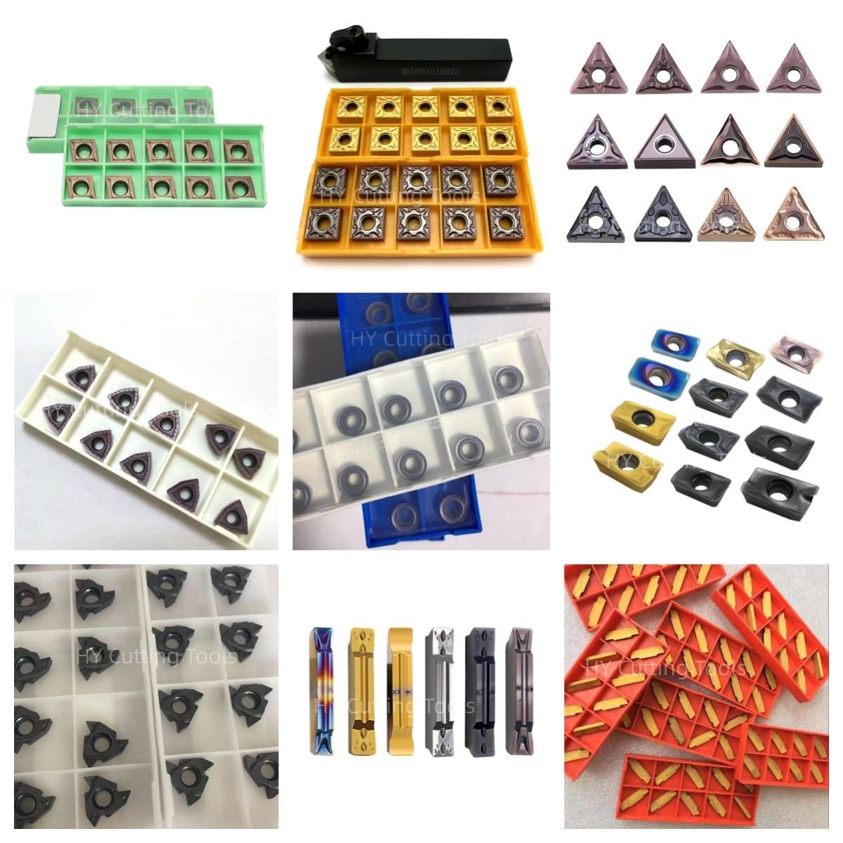

Share a line-by-line list of insert codes and quantities for a mixed-size quotation. Stock status, minimum quantity, sample requirements and production lead time are confirmed for each grade, coating and configuration.
Send your item list and quality requirements through our contact form for specification, availability and delivery confirmation.
Product FAQs
What is the difference between CCMT09T304-FG and CCMT09T308-FG?
The supplied FG table gives both inserts the same L 9.7 mm, IC 9.525 mm, thickness 3.97 mm and fixing-hole diameter 4.4 mm. CCMT09T304-FG has a 0.4 mm corner radius; CCMT09T308-FG has a 0.8 mm radius.
Which radius should I choose for steel finishing?
Select the radius in relation to the required surface finish, feed, stock allowance and rigidity. A 0.4 mm radius can help with finer features and lower cutting force; a 0.8 mm radius may provide more corner support in a stable setup. Check the FG chipbreaker's recommended operating range for the exact cermet grade.
Are the FG inserts suitable for internal boring?
They may be considered with a compatible CCMT 09-size boring bar. Confirm insert seat, clamp, tool orientation, minimum bore, clearance and bar overhang. The insert chart alone does not establish a minimum bore size or maximum overhang.
Which cermet grade and coating do these FG inserts use?
The supplied images do not name a substrate grade or coating for the FG rows. Confirm the grade designation, coating and edge preparation from the product label or supplier specification before selecting cutting data.
Can I use these inserts for stainless steel, hardened steel, cast iron or aluminum?
The general product-information image lists several workpiece materials, but it does not establish an FG grade or application range for each material. This page is positioned for steel finishing; confirm any other workpiece against the exact grade's application data and a machining trial.
Does the “diamond insert” description mean PCD?
No. In the supplied model image, “diamond” describes the 80° rhombic insert shape. It does not identify a polycrystalline diamond cutting material. Confirm that the supplied FG variant is cermet through its grade specification.
Ordering & OEM FAQs
What should I include in an inquiry?
Send CCMT09T304-FG or CCMT09T308-FG, quantity, holder or boring-bar model, steel grade and hardness, operation, finishing allowance, current cutting conditions and required surface finish. Include the grade code or box-label photo when replacing an existing insert.
Can I request a specific grade or custom packaging?
Provide the requested grade, coating or performance target and the packaging or branding requirements. Material, availability, MOQ and lead time must be confirmed for the selected full ordering code.
Are CCMT09T304-HQ, -MT or -TC equivalent to -FG?
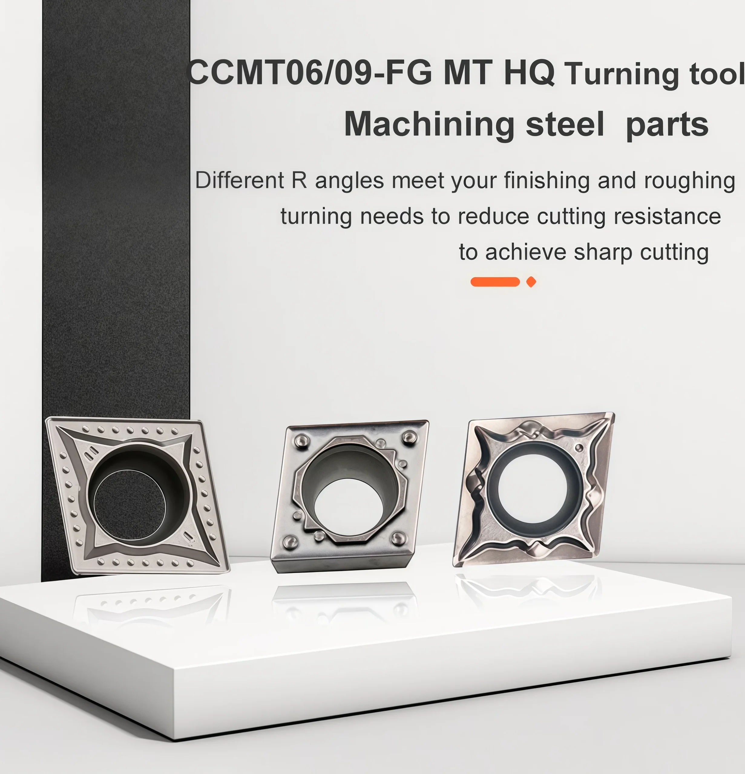
Not automatically. The supplied images show HQ in an illustrative model breakdown and MT/TC as separate table rows. Suffixes can identify different chipbreaker designs; compare the complete code, grade, application range and holder fit before treating another suffix as a replacement.
Downloads & Technical Reference
For shape, radius, chipbreaker and grade selection, read our CNC Insert Selection Guide.
Review the supplied FG dimension chart and model illustration. Confirm the actual cermet grade and cutting data for the order.
Need Sizes, Pricing or Custom Options?
Send us the required tool type, sizes, quantities, workpiece material and any OEM or custom requirements. We will confirm suitable specifications, availability, lead time and quotation details.
Drawings, size lists and reference photos are welcome.