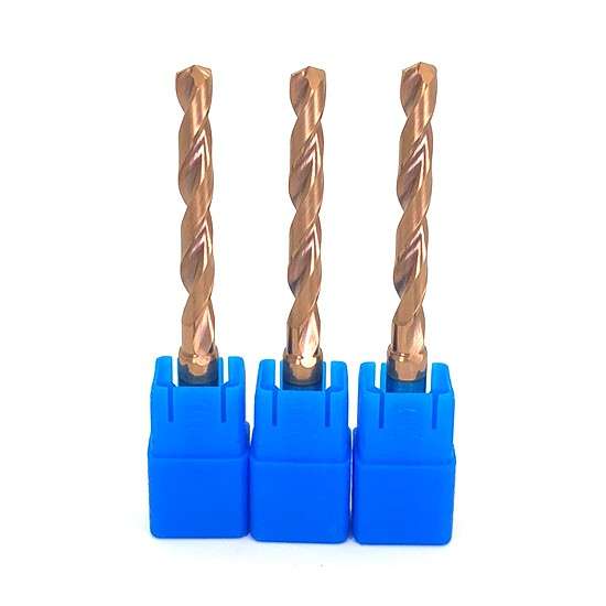
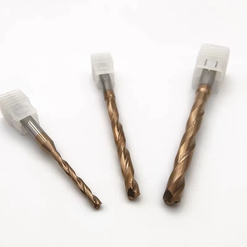
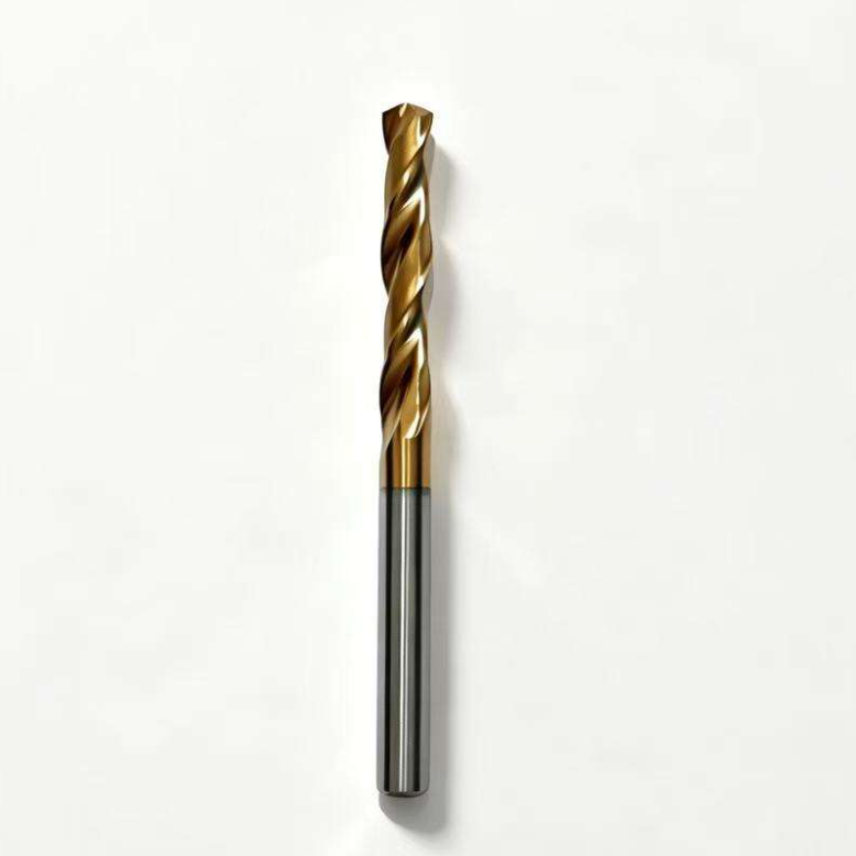
135° Split-Point Solid Carbide Twist Drill for Steel
Consistent Quality
Consistent geometry across repeat orders.
سفارشهای انعطافپذیر
Small batches and mixed sizes available.
OEM Support
Custom marking, labels and packaging.
استاندارد و سفارشی
Standard sizes and custom configurations.
135° Split-Point Solid Carbide Twist Drill Overview
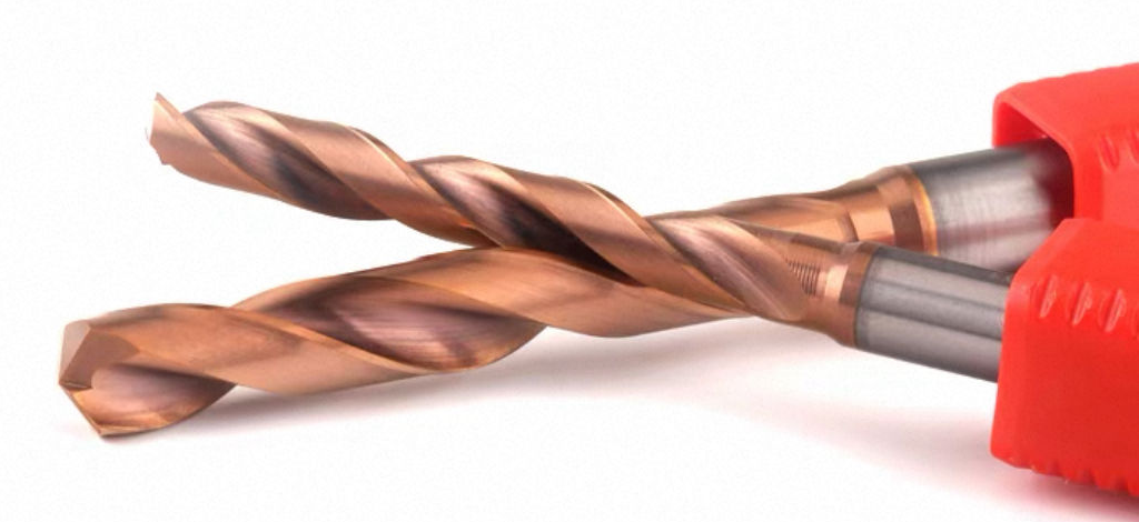
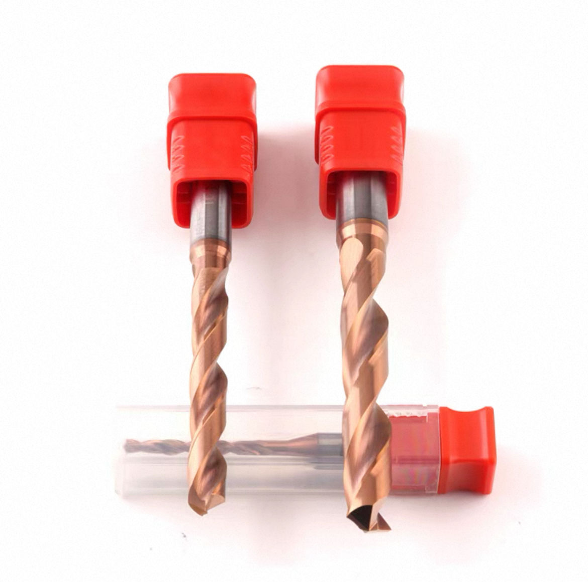
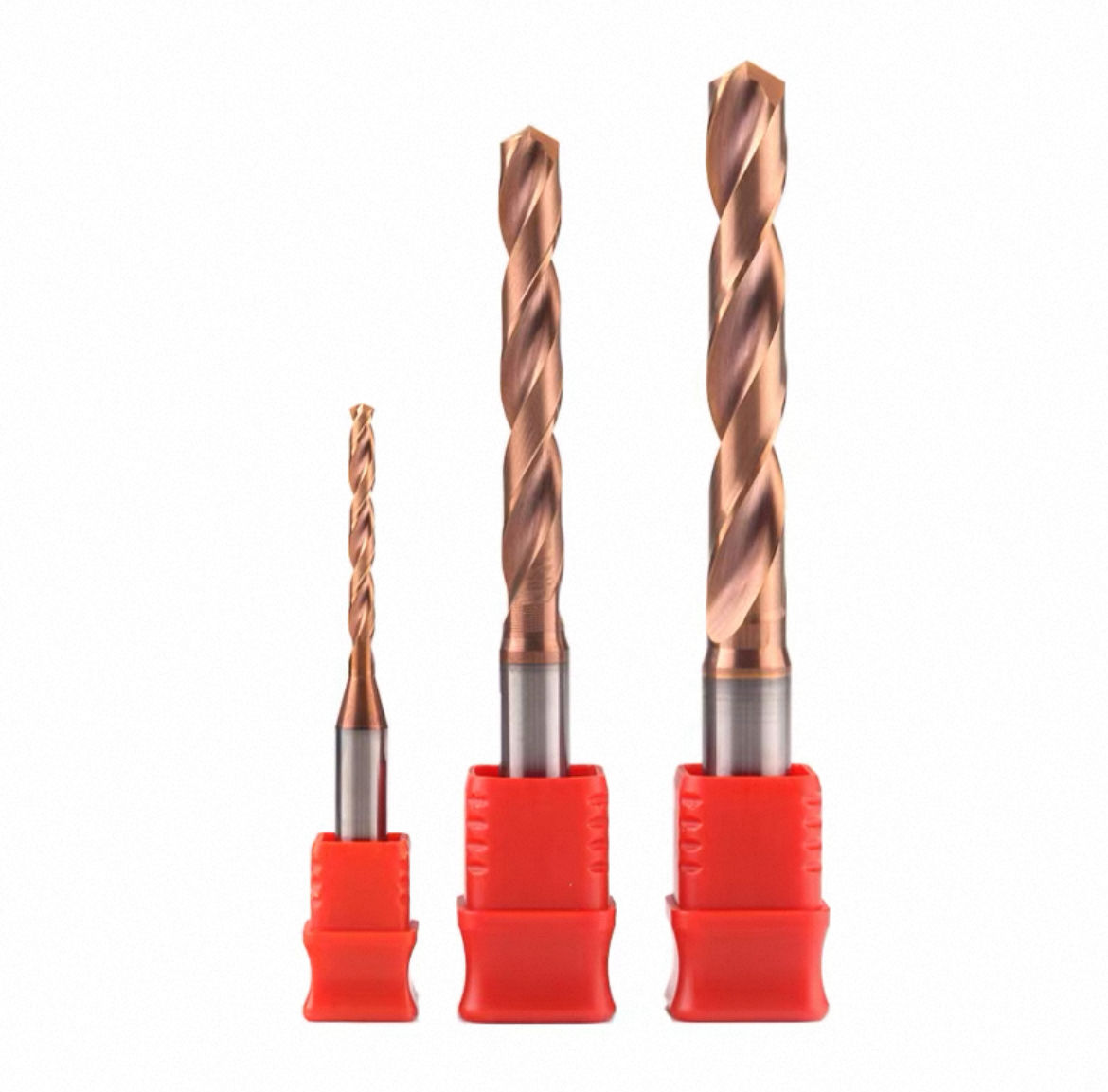
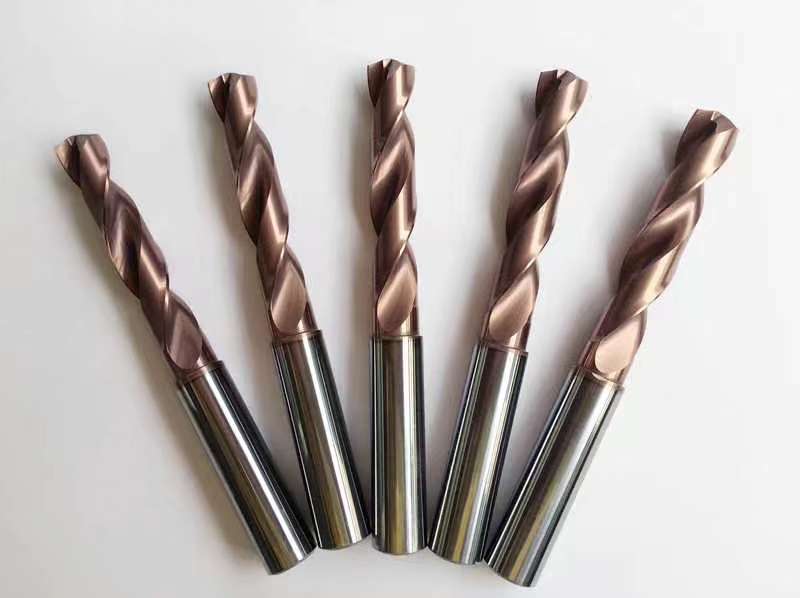
This 135° Split-Point Solid Carbide Twist Drill is designed for stable and accurate hole machining in carbon steel, alloy steel and pre-hardened steel. The split-point geometry improves positioning at hole entry and helps reduce drill walking, while the 135° point angle supports controlled penetration in CNC drilling. Manufactured from fine-grain solid carbide, the drill provides high rigidity, reliable wear resistance and consistent dimensional performance. Two spiral flutes support continuous chip evacuation in blind-hole and through-hole machining. Standard 3×D, 5×D and 8×D configurations are available from Ø3.0 to Ø20.0 mm.
135° Split Point
3×D / 5×D / 8×D
Ø3.0–20.0 mm
ISO P Steel
Key Configuration
135° Split-Point Geometry
The split-point design improves centering at hole entry and helps reduce drill walking on suitable flat workpiece surfaces.
Thinned Chisel Edge
A reduced chisel-edge area helps lower axial entry resistance and supports a more controlled initial penetration.
Fine-Grain Solid Carbide
The rigid carbide body provides cutting-edge support and dimensional stability for repeated CNC drilling in steel.
Key Product Advantages
Stable Hole Entry
The 135° split point supports stable positioning and helps limit drill walking during entry on a properly prepared flat surface.
Reduced Entry Resistance
Split-point thinning reduces the effective chisel-edge load, supporting smoother initial penetration under rigid CNC conditions.
Two-Flute Chip Evacuation
Two precision-ground spiral flutes guide chips away from the cutting zone in blind-hole and through-hole drilling.
3D / 5D / 8D Selection
Three depth series allow the drill length to be matched to the required hole depth while balancing rigidity, chip removal and tool overhang.
Workpiece Material Compatibility
Applications & Target Scope
- Blind-hole drilling in carbon and alloy steel
- Through-hole drilling in general CNC production
- Precision hole machining requiring stable entry
- Mechanical and mold component machining
- 3D, 5D and 8D steel drilling with confirmed coolant and machine conditions
Product & Cutting-Edge Details
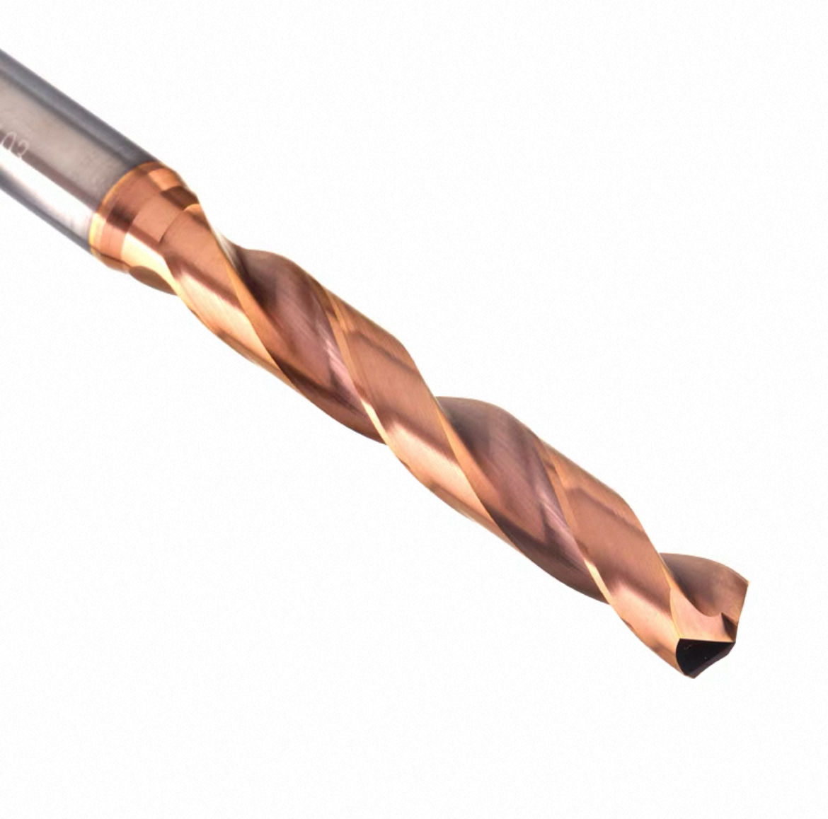
Tool Nomenclature & Dimensions
This 135° split-point solid carbide twist drill series is available from Ø3.0 to Ø20.0 mm in 3×D, 5×D and 8×D configurations. The standard construction uses two spiral flutes and a cylindrical straight shank. Final shank diameter, point preparation, coating and coolant method should be confirmed before ordering.

3D, 5D & 8D Standard Size Matrix
Standard dimensions from the original product specification are listed below. All dimensions are in millimetres.
| d1 | 3D L1 | 3D L | 5D L1 | 5D L | 8D L1 | 8D L |
|---|---|---|---|---|---|---|
| 3 | 20 | 62 | 28 | 66 | 30 | 70 |
| 4 | 24 | 66 | 36 | 74 | 42 | 83 |
| 5 | 28 | 66 | 44 | 82 | 50 | 90 |
| 6 | 28 | 66 | 44 | 82 | 57 | 97 |
| 7 | 34 | 79 | 53 | 91 | 76 | 116 |
| 8 | 41 | 79 | 53 | 91 | 76 | 116 |
| 9 | 47 | 89 | 61 | 103 | 87 | 131 |
| 10 | 47 | 89 | 61 | 103 | 95 | 139 |
| 11 | 55 | 102 | 71 | 118 | 106 | 155 |
| 12 | 55 | 102 | 71 | 118 | 114 | 163 |
| 13 | 60 | 107 | 77 | 124 | 133 | 182 |
| 14 | 60 | 107 | 77 | 124 | 133 | 182 |
| 15 | 65 | 115 | 83 | 133 | 152 | 204 |
| 16 | 65 | 115 | 83 | 133 | 152 | 204 |
| 17 | 73 | 123 | 93 | 143 | 171 | 223 |
| 18 | 73 | 123 | 93 | 143 | 171 | 223 |
| 19 | 79 | 133 | 101 | 153 | 190 | 244 |
| 20 | 79 | 133 | 101 | 153 | 190 | 244 |
135° Split-Point Steel Drilling Guidance
- Flat-Surface Entry: The split point supports stable entry and reduced drill walking on suitable flat workpiece surfaces.
- 3D Drilling: Use when higher rigidity, short-cycle machining and shallow-hole production are priorities.
- 5D Drilling: Suitable for medium-depth holes with stable chip evacuation and consistent coolant delivery.
- 8D Drilling: Requires low runout, good machine rigidity, reliable chip removal and conservative starting parameters.
Recommended Starting Cutting Parameters
The original product page provides the following starting references. Actual speed and feed depend on drill diameter, drilling depth, coating, steel grade, hardness, tool overhang, machine rigidity and coolant condition.
| WORKPIECE MATERIAL | HARDNESS | Vc (m/min) | FEED GUIDANCE | COOLANT |
|---|---|---|---|---|
| Carbon Steel | Below HRC30 | 70–110 | Adjust according to drill diameter and hole depth | External coolant or suitable emulsion |
| Alloy Steel | HRC30–45 | 50–85 | Reduce speed and feed as hardness and depth increase | Stable external coolant |
| Pre-Hardened / Mold Steel | HRC45–55 | 30–55 | Use a rigid setup, minimal runout and conservative feed | Consistent coolant supply |
Solid Carbide Drill Product Family Overview
Select the drill according to point geometry, required depth and workpiece condition.
135° Split-Point Drill
Steel / 3D–8D (Current)
Stub-Length Drill
High-Rigidity Short Holes
Jobber-Length Drill
General CNC Drilling
Custom Twist Drill
Special Diameter / Length
For additional sizes and related drill series, View the Solid Carbide Drill Catalog .
135° Split-Point Drill Customization
Cutting diameter, flute length, overall length, 135° split-point geometry, cutting-edge preparation, coating and dimensional tolerance can be configured for steel hole machining. Each configuration is reviewed according to the steel grade, hardness, hole depth, required accuracy and machining conditions.
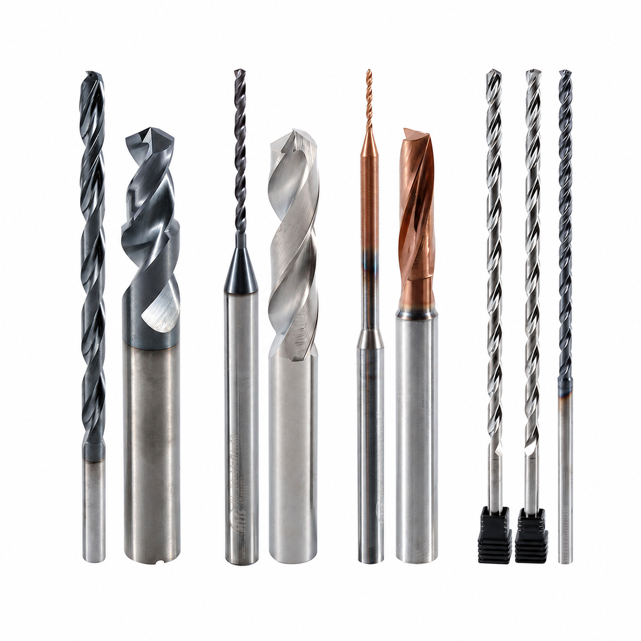
135° Split-Point Geometry & Edge Preparation
The 135° point, split-point thinning, web thickness, margin design and cutting-edge preparation can be configured to support controlled entry, reduced drill walking and stable cutting in steel.

Diameter & Length Options
Metric, fractional-inch and drawing-defined diameters can be configured with application-matched flute lengths, overall lengths and shank dimensions for steel drilling.
خدمات OEM و برند خصوصی
OEM manufacturing and private-label supply options for industrial distributors, tooling brands and steel-machining customers.
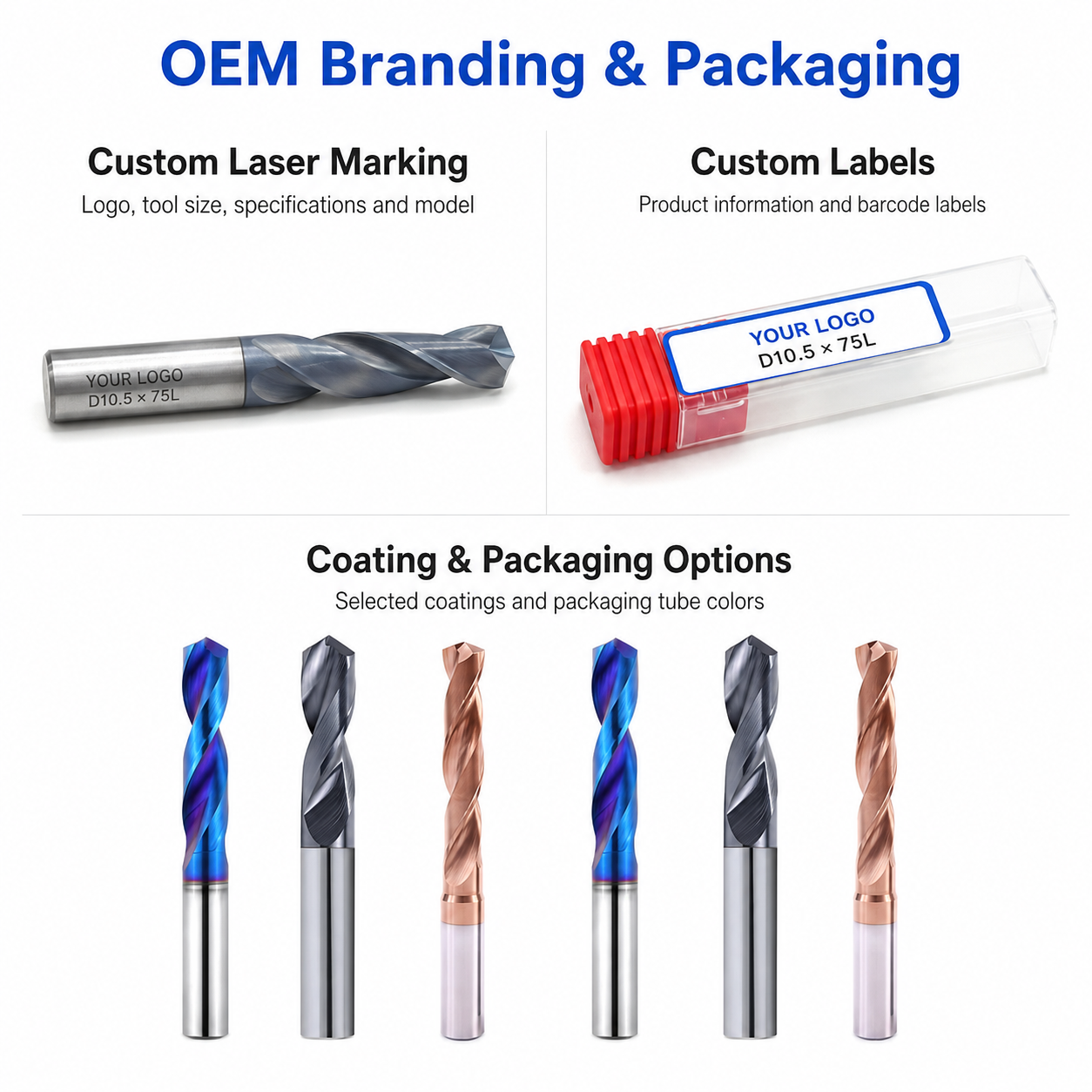
Laser Etching
Custom laser marking for logos, tool codes, diameter specifications, coating identification and batch numbers.
Custom Packaging
Individual protective tubes, diameter labels, multi-pack boxes, custom inserts and private-label packaging options.
Commercial Terms
Flexible MOQ options for standard configurations, custom sizes, trial orders and scheduled repeat supply.
Technical Workflow
Inquiry
Submit the steel grade, hardness, hole dimensions, tolerance and required quantity.
Engineering
The 135° split point, flute geometry, edge preparation and coating are reviewed.
Commercial
Quotation, MOQ, production schedule and delivery terms are confirmed.
Production
CNC grinding, split-point formation, edge preparation, coating and tool identification.
Quality Control
Cutting diameter, 135° point geometry, split-point symmetry, runout and cutting edges are inspected before dispatch.
Inspection & Quality Control
Drill dimensions, cutting-edge geometry and visible surface condition are checked according to the confirmed product specification and application requirements.

Protective Packing for Shipment
Finished drills are protected individually before batch labeling and export-carton reinforcement.

Individual Tool Protection
Each drill is individually protected in a plastic tube to reduce contact damage during storage, handling and transportation.
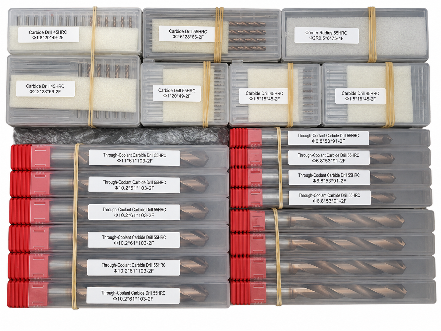
Batch & Label Verification
Tools are grouped and labeled by specification to support order verification before carton packing.

Export Carton Protection
Batch packaging, cushioning materials and reinforced export cartons are selected according to the order quantity and shipping method.
Reference Lead Time
The following timeframes are general references. Availability and production scheduling are reviewed for each order.
Shipping Options
Shipping arrangements can be selected according to order size, delivery schedule and destination.

Product FAQs
Product-specific information about 135° split-point geometry, steel drilling, hole-entry stability, chip evacuation, coating selection and machining requirements.
What is the purpose of the 135° split-point geometry?
The 135° split-point geometry is designed to support stable centering and controlled entry in steel. The split point reduces the effective chisel-edge load and helps limit drill walking when the tool is used with a rigid setup, low runout and a suitable entry surface.
What types of steel can this carbide drill machine?
The drill can be configured for carbon steel, alloy steel and other confirmed ISO P steel applications. Final suitability depends on the exact material grade, hardness, heat treatment, hole depth, coating and cutting conditions, so these details should be confirmed before ordering.
Does a 135° split point eliminate the need for spot drilling?
Not in every application. A 135° split point supports more stable self-centering on a suitable flat surface, but spot drilling or dedicated entry preparation may still be required for inclined, curved, interrupted or poorly supported surfaces, or where very tight positional accuracy is required.
What machining conditions are important for accurate steel drilling?
Use a rigid machine setup, low spindle and holder runout, secure clamping and the shortest practical tool overhang. Stable feed and effective coolant delivery are also important for controlling cutting heat, chip evacuation and hole consistency.
Can the diameter, flute length and coating be customized?
Yes. Cutting diameter, flute length, shank diameter, overall length, edge preparation and coating can be reviewed according to the steel grade, hardness, required hole depth and machine setup. Non-standard dimensions can also be evaluated from a customer drawing.
What information is required for a quotation?
Please provide the cutting diameter, hole depth, required tolerance, steel grade, hardness or heat-treatment condition, flute length, shank diameter, overall length, coolant method, machine type and required quantity. A drawing is recommended for non-standard dimensions or special hole requirements.
Ordering & OEM FAQs
General information for trial orders, mixed sizes, OEM marking and repeat distributor supply.
Do you accept small trial orders?
Yes. Small trial quantities can be reviewed for hole-quality testing, dimensional verification and tool-life evaluation before larger repeat orders.
Can mixed drill sizes be ordered together?
Yes. Different cutting diameters and length configurations can normally be combined in one order when the carbide grade, coating and production requirements are compatible.
Is OEM laser marking available?
Yes. Logo, item code, tool size and batch identification can be reviewed for laser marking where the available shank area permits. Custom labels and private-brand packaging are also available for OEM programs.
What is the typical production lead time?
Lead time depends on diameter, flute length, coating, custom geometry and order quantity. Final production scheduling is confirmed after the product specification and application requirements are approved.
Downloads & Technical Resources
Access drill series information and starting cutting-data references for solid carbide drilling in steel.
Need Sizes, Pricing or Custom Options?
Send us the required tool type, sizes, quantities, workpiece material and any OEM or custom requirements. We will confirm suitable specifications, availability, lead time and quotation details.
Drawings, size lists and reference photos are welcome.