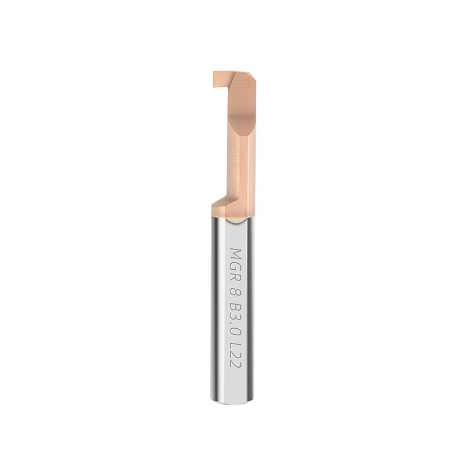
MGR Series Solid Carbide Micro Internal Grooving Bar for Small Bore Machining
Calidad constante
Consistent geometry across repeat orders.
Pedidos flexibles
Small batches and mixed sizes available.
OEM Support
Custom marking, labels and packaging.
Herramientas estándar y personalizadas
Standard sizes and custom configurations.
MGR Carbide Micro Internal Grooving Bar Overview
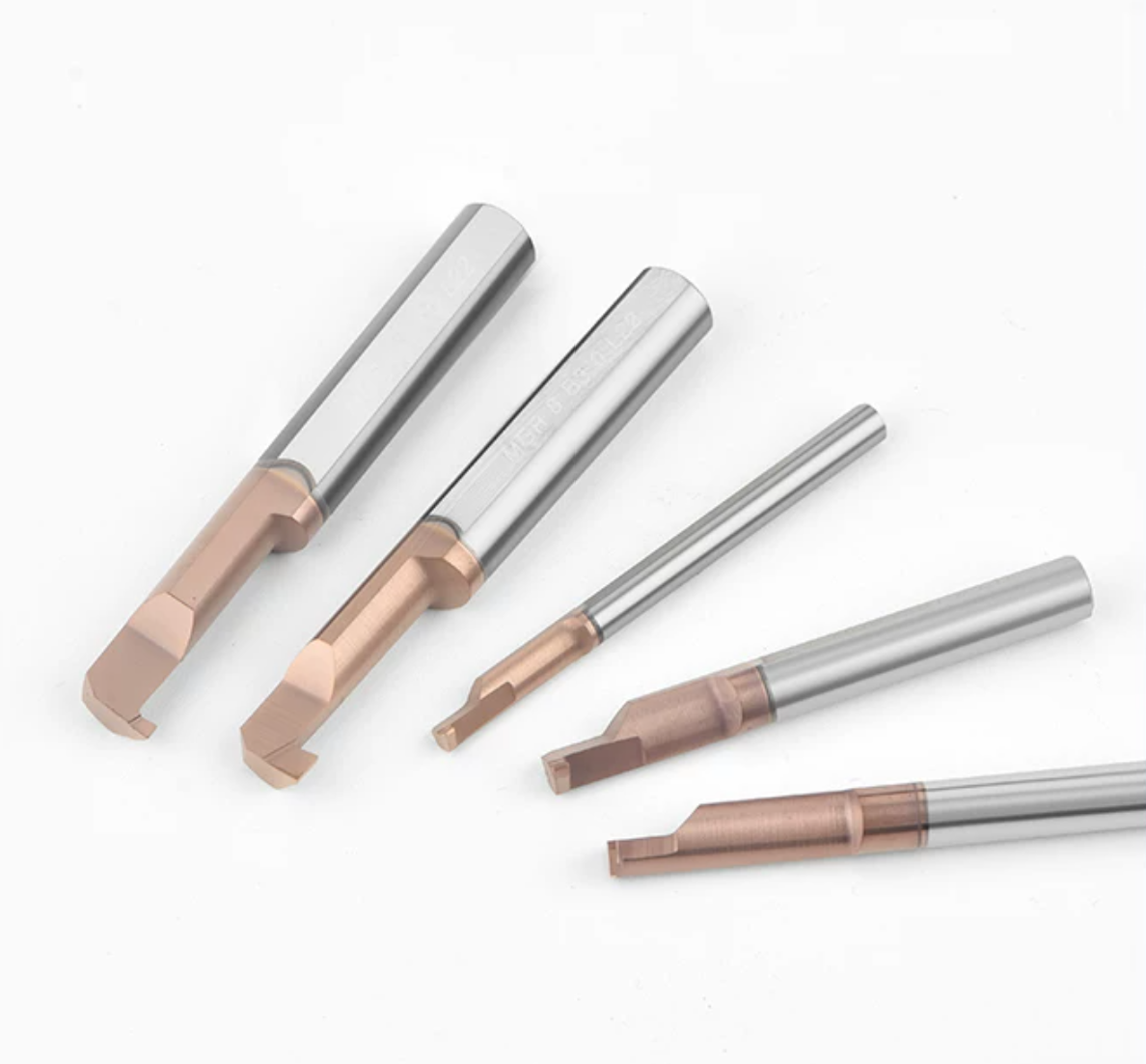
MGR Series solid carbide micro internal grooving bars are designed for machining precision grooves and narrow recesses inside small-diameter bores. The standard range covers actual cutting diameters from Ø2.9 mm to Ø7.9 mm, with groove widths from 0.5 mm to 3.0 mm.
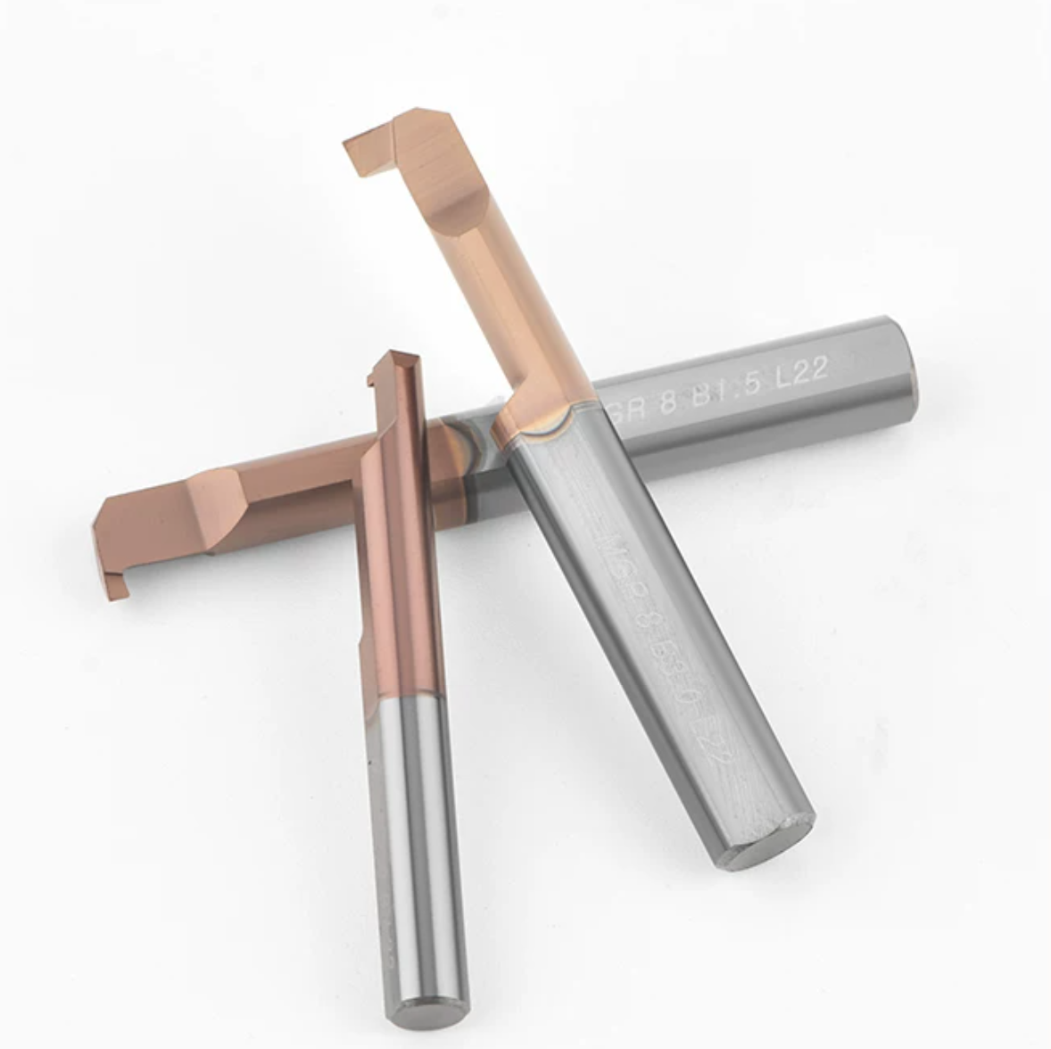
The one-piece fine-grain solid carbide construction provides the rigidity required for small-bore CNC turning. Precision-ground cutting geometry helps maintain groove width, groove depth and surface quality when machining compact precision components.
Key Product Features
Typical Applications
| Aplicación | Requisito de mecanizado |
|---|---|
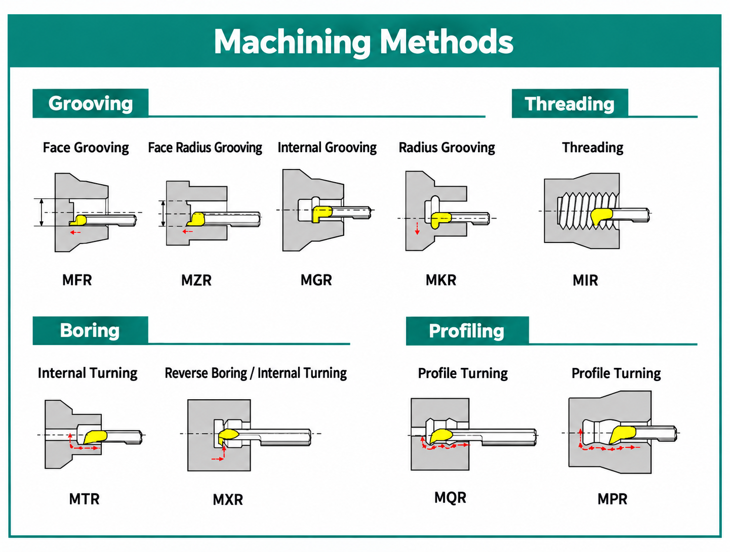
| Precision Internal Grooves | Machining controlled groove widths and depths inside small-diameter bores. |
| Internal Relief Grooves | Producing narrow relief features close to internal shoulders or functional surfaces. |
| Retaining-Ring Grooves | Machining narrow internal grooves when the specified width, depth and corner geometry match the selected tool. |
| Miniature Precision Components | Suitable for sleeves, bushings, hydraulic parts, instrument components and precision-turned parts. |
Recommended Workpiece Materials
Carbon Steel, Alloy Steel, Stainless Steel and Copper Alloys
Pre-Hardened Steel, Hardened Steel Below 48 HRC, Cast Iron and Titanium Alloys
Coating, cutting-edge preparation and machining parameters should be selected according to workpiece material, groove dimensions, tool overhang and machine rigidity.
Compatibilidad de la máquina

Product Video
Product details and configurations of HY solid carbide micro internal tooling.
Selection Recommendation
Select the MGR bar according to the bore diameter, groove width B, groove depth Q and groove position. Use the largest possible shank and the shortest practical clearance length to improve rigidity. Confirm that the tool body has sufficient clearance throughout the cutting and retraction path before machining.
Tool Nomenclature & Selection Guide
Select the MGR micro internal grooving bar according to actual cutting diameter, groove width, groove depth, clearance length and shank diameter.
| Code Element | Descripción | Example |
|---|---|---|
| MGR | Micro Internal Grooving Bar | MGR Series |
| 29 / 39 / 49 / 59 / 79 | Actual Cutting Diameter d1 | Ø2.9 / Ø3.9 / Ø4.9 / Ø5.9 / Ø7.9 mm |
| B050–B300 | Groove Width B | 0.5–3.0 mm |
| L100 / L150 / L200 | Clearance Length L1 | 10 / 15 / 20 mm |
| 450 / 550 / 650 / 860 | Shank Diameter and Overall Length | Ø4 × 50 / Ø5 × 50 / Ø6 × 50 / Ø8 × 60 mm |
Dimensions & Available Sizes
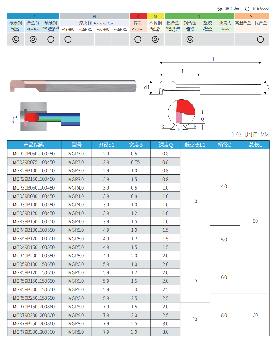
Dimensions are shown in millimeters. Custom groove widths, depths, reach lengths and shank configurations can be produced according to drawings and machining requirements.
Standard Model Range
| Modelo | Cutting Dia. d1 | Groove Width B | Corresponding Depth Q | Clearance L1 | Shank D | Overall L |
|---|---|---|---|---|---|---|
| MGR3.0 | 2.9 mm | 0.5 / 0.75 / 1.0 / 1.5 | 0.8 mm | 10 mm | 4 mm | 50 mm |
| MGR4.0 | 3.9 mm | 0.5 / 0.8 / 1.0 / 1.2 / 1.5 | 1.0 mm | 10 mm | 4 mm | 50 mm |
| MGR5.0 | 4.9 mm | 1.0 / 1.2 / 1.5 / 2.0 | 1.5 / 1.5 / 1.5 / 2.0 | 10 mm | 5 mm | 50 mm |
| MGR6.0 | 5.9 mm | 1.0 / 1.2 / 1.5 / 2.0 / 2.5 | 2.0 / 2.0 / 2.0 / 2.5 / 2.5 | 15 mm | 6 mm | 50 mm |
| MGR8.0 | 7.9 mm | 1.5 / 2.0 / 2.5 / 3.0 | 2.0 / 2.5 / 3.0 / 3.0 | 20 mm | 8 mm | 60 mm |
Where several groove widths and depths are listed, the values correspond in the same left-to-right order.
Specification Summary
Material Suitability
| Suitability | Workpiece Materials |
|---|---|
| Best | Carbon Steel, Alloy Steel, Stainless Steel and Copper Alloys |
| Good | Pre-Hardened Steel, Hardened Steel Below 48 HRC, Cast Iron and Titanium Alloys |
Selection & Setup Guidance
Bore clearance: Confirm that the actual bore diameter is larger than the tool cutting diameter d1 and that sufficient radial clearance is available.
Groove dimensions: Select groove width B and depth Q directly from the size table. Do not exceed the listed standard groove depth.
Tool overhang: Use the shortest practical overhang and the largest shank diameter permitted by the component geometry.
Center height: Set the cutting edge accurately on the spindle centerline to reduce uneven cutting forces and edge damage.
Coolant and chip control: Direct coolant toward the cutting zone and confirm that chips can leave the groove without becoming trapped inside the bore.
Related Micro Internal Grooving Series
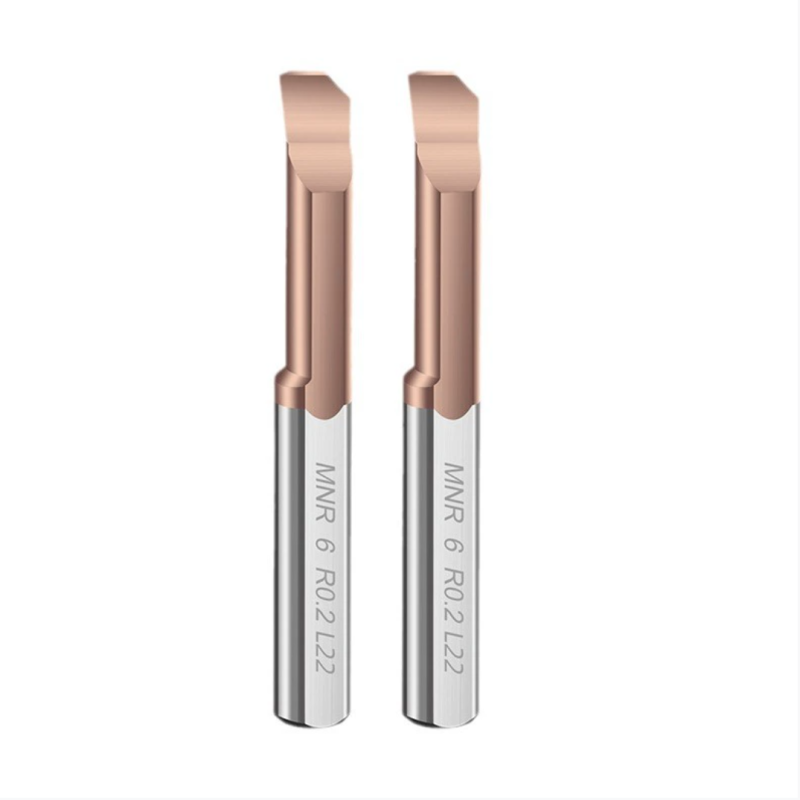
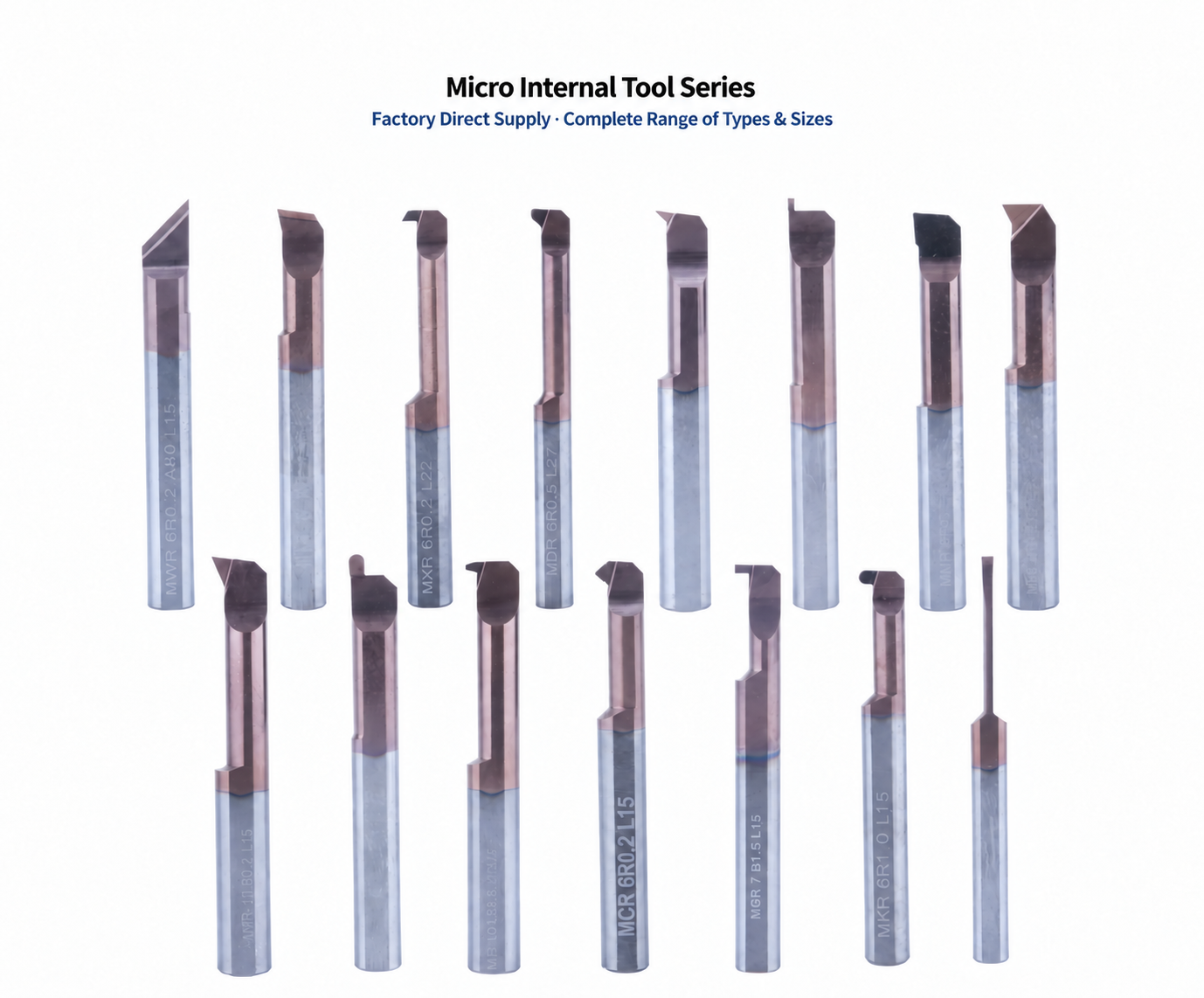
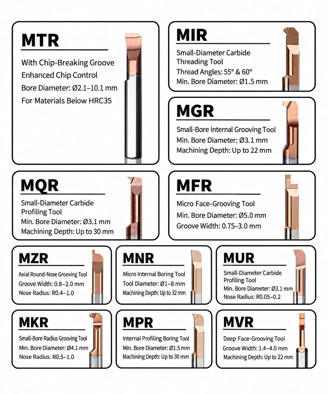
Grooving & Boring: MNR Series
Radius Internal Grooving: MKR Series
Thread Relief Grooving: MDR Series
We support distributors, tooling suppliers and industrial partners with flexible OEM and private label solutions for micro internal tooling products. From laser marking and customized packaging to product identification and technical documentation, we help customers build their own tooling product lines with reliable manufacturing support.
OEM Product Scope
We provide OEM and private label manufacturing solutions for micro internal tooling products, supporting distributors and tooling suppliers with standard series, customized specifications and drawing-based production.
MPR series and customized small-diameter boring tools for precision internal machining and anti-vibration applications.
MIR/MIL series with customized thread profiles, dimensions and product identification requirements.
Internal grooving and special groove solutions for miniature precision components.
Non-standard dimensions, special geometries and customer drawing-based tooling solutions are available.

Customization Options
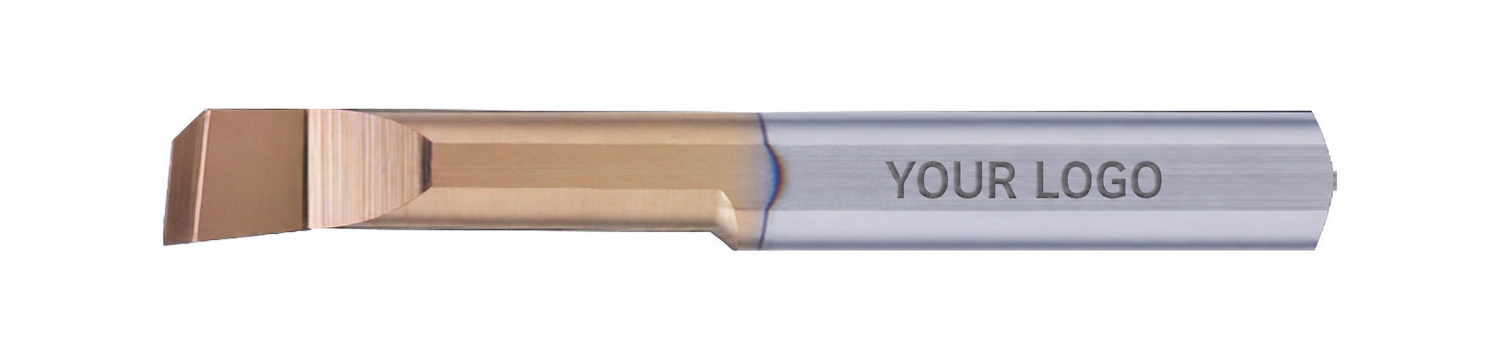
Laser Marking & Product Identification
Custom logo, model number and product identification marking can be provided according to distributor and brand requirements.
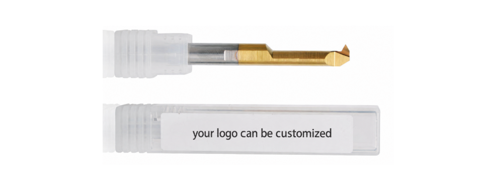
Custom Packaging
Individual packaging, labels and product information can be customized to support reseller sales channels and private brand development.
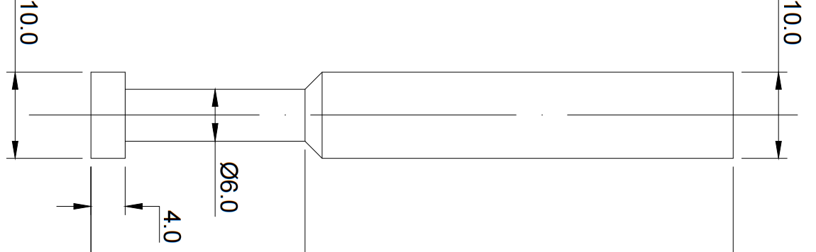
Technical Documents & Product Support
Support technical drawings, specifications and product information to help distributors promote and manage their tooling products.
OEM Workflow
Confirm drawings, specifications, materials and packaging requirements.
Finalize tool design, marking details and production requirements.
Provide samples for testing and approval before batch production.
Produce and inspect according to confirmed requirements.
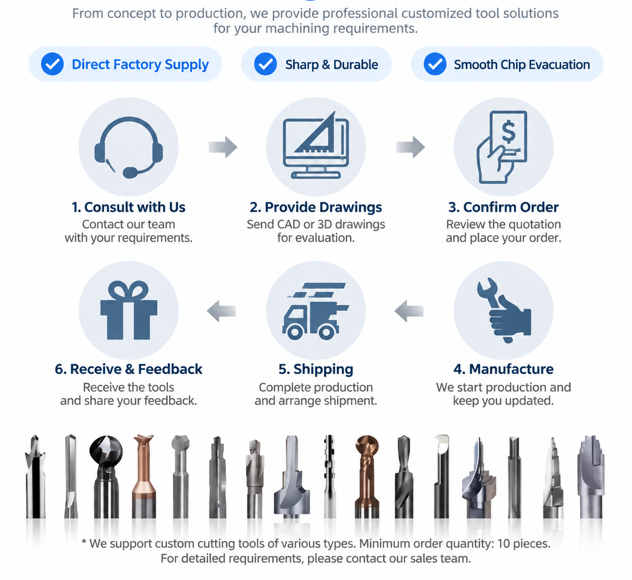
Private Label Support for Distributors
For distributors and tooling resellers, we provide flexible private label support including customized marking, packaging solutions and product documentation to help establish a professional tooling product range.
We follow strict quality control procedures from raw material inspection to final shipment. Each tool is inspected to ensure consistent dimensions, cutting performance and reliable quality for industrial machining applications.
Proceso de control de calidad

Verify carbide material quality and consistency before production.
Control tool geometry, dimensions and cutting edge accuracy during manufacturing.
Inspect edge quality and surface finish to maintain stable cutting performance.
Confirm product specifications before packing and shipment.
Inspection Standards
| Inspection Item | Purpose |
|---|---|
| Material Inspection | Verify carbide quality and material consistency. |
| Dimension Inspection | Confirm tool size and tolerance requirements. |
| Cutting Edge Inspection | Check edge geometry and surface quality. |
| Final Inspection | Ensure products meet confirmed specifications before delivery. |
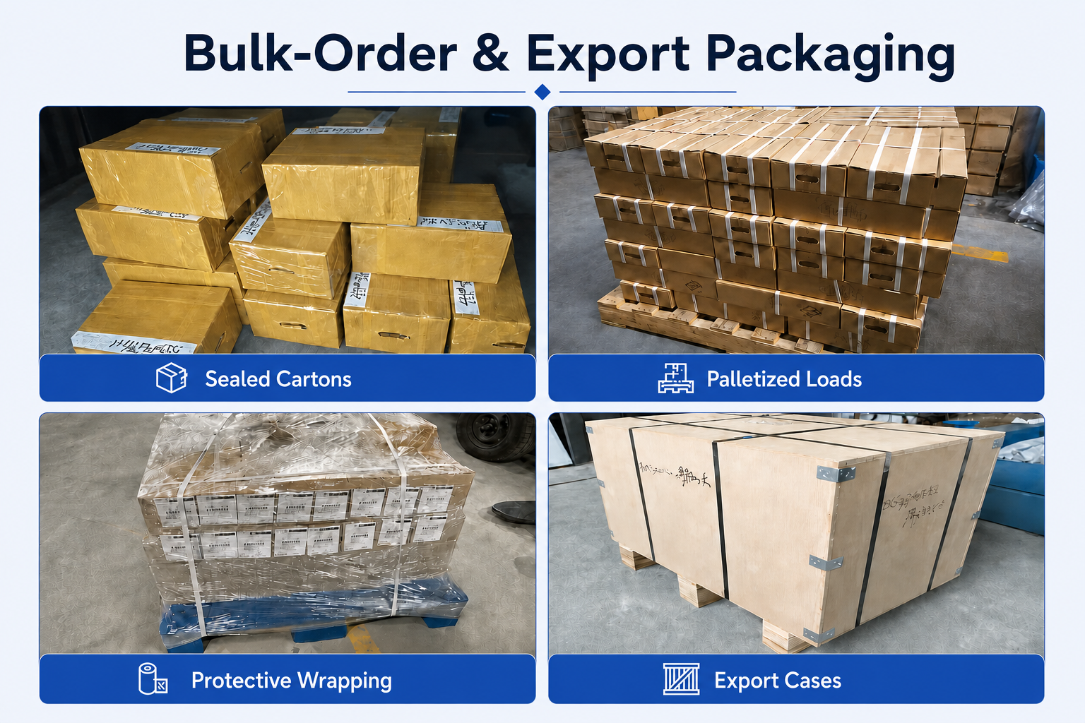
Packing & Protection

Individual protection and export packaging help prevent tool damage during storage and international transportation.
- Individual tool protection
- Product identification labels
- Batch traceability support
- Export shipment protection
Production & Delivery Workflow
Confirmación del pedido
Production Scheduling
Quality Inspection
Packing
Shipment

Delivery Support
Standard products can usually be shipped within 1–3 working days after order confirmation. Customized products require confirmation according to tool design, quantity and production requirements.
FAQ & Downloads
Product FAQs
What are MGR micro internal grooving bars used for?
MGR Series solid carbide bars are designed for machining precision grooves, relief grooves and narrow recesses inside small-diameter bores. Typical applications include sleeves, bushings, hydraulic components, instrument parts and other precision-turned components.
What bore sizes can the MGR Series machine?
The standard range includes MGR3.0, MGR4.0, MGR5.0, MGR6.0 and MGR8.0 size classes. Their actual cutting diameters are Ø2.9, Ø3.9, Ø4.9, Ø5.9 and Ø7.9 mm respectively. The workpiece bore must provide sufficient clearance for the selected tool and its complete cutting path.
What groove widths are available?
Standard groove widths range from 0.5 mm to 3.0 mm. The available width depends on the selected tool size: MGR3.0 starts from 0.5 mm, while the larger MGR8.0 models are available in widths from 1.5 mm to 3.0 mm.
What groove depths can be machined?
Standard groove depths range from 0.8 mm to 3.0 mm. The maximum depth depends on the cutting diameter and groove width. For example, MGR3.0 tools have a standard depth of 0.8 mm, while selected MGR8.0 tools can machine grooves up to 3.0 mm deep.
What materials can be machined with MGR grooving bars?
The MGR Series is primarily suitable for carbon steel, alloy steel, stainless steel and copper alloys. It can also be used for pre-hardened steel, hardened steel below approximately 48 HRC, cast iron and selected titanium alloys when the coating, edge preparation and cutting conditions are correctly matched.
What machines are compatible with MGR internal grooving bars?
MGR tools can be used on CNC turning centers, Swiss-type CNC lathes, automatic lathes and other precision turning machines equipped with a suitable tool holder or clamping sleeve.
Selection & Application FAQs
How do I select the correct MGR model?
First confirm the bore diameter and select an MGR cutting diameter that provides sufficient clearance. Then select the required groove width B, groove depth Q and clearance length L1. The shank diameter must also match the available holder or clamping sleeve.
What is the difference between cutting diameter d1 and shank diameter D?
The cutting diameter d1 determines whether the cutting section can enter the bore. The shank diameter D is the cylindrical section held by the tool holder. For example, an MGR3.0 tool has an actual cutting diameter of Ø2.9 mm but uses a Ø4 mm shank.
How do I select the clearance length L1?
The clearance length must be long enough to reach the groove position without the larger tool body contacting the bore. Standard L1 lengths are 10, 15 and 20 mm. Use the shortest length that can safely reach the groove because a shorter overhang generally provides better rigidity.
How can I improve machining stability in a small bore?
Use the largest possible shank, keep the tool overhang as short as practical and set the cutting edge accurately on the spindle centerline. The holder must clamp the complete shank securely. Cutting speed and feed should be adjusted according to groove width, material hardness and machine rigidity.
How should coolant and chips be managed during internal grooving?
Direct coolant toward the cutting zone whenever possible and verify that chips can leave the groove and bore freely. Trapped chips can damage the groove surface or cutting edge. For restricted or deeper grooves, a pecking strategy may improve chip evacuation.
Can the tool cut sideways to widen an internal groove?
Standard MGR bars are primarily intended for radial plunging to produce the specified groove width. Lateral turning should only be used when the selected cutting geometry and application have been confirmed for that operation. For a wider groove, multiple controlled plunges or a custom-width tool is normally recommended.
Ordering & OEM FAQs
Can you manufacture custom MGR internal grooving bars?
Yes. Cutting diameter, groove width, groove depth, corner radius, clearance length, shank diameter, overall length, coating and cutting geometry can be customized according to component drawings or reference samples.
What information is required for an MGR quotation?
Please provide the standard model or product code, bore diameter, groove width, groove depth, groove position, workpiece material, required quantity and any coating requirements. A component drawing is recommended when the groove is close to an internal shoulder or clearance is limited.
Can I order mixed models for initial testing?
Yes. Small trial orders and mixed standard sizes can be reviewed according to current stock and production availability. The standard minimum order quantity is 10 pieces.
Do you provide private-label and OEM packaging?
Yes. Custom laser marking, model identification, labels and private-label packaging are available for distributors and tooling resellers. Please provide the logo file and packaging requirements when requesting a quotation.
What is the lead time for MGR grooving bars?
In-stock standard models can usually be dispatched within 1–3 working days after order confirmation. Lead time for customized tools depends on the dimensions, cutting geometry, coating, quantity and packaging requirements.
Recursos técnicos
Need Sizes, Pricing or Custom Options?
Send us the required tool type, sizes, quantities, workpiece material and any OEM or custom requirements. We will confirm suitable specifications, availability, lead time and quotation details.
Drawings, size lists and reference photos are welcome.