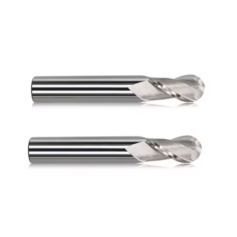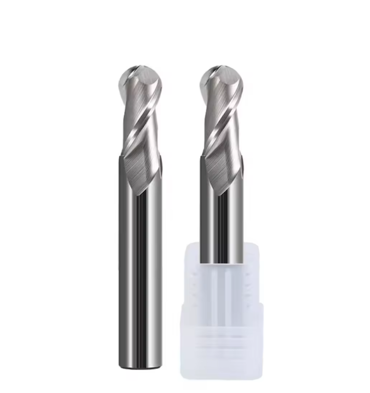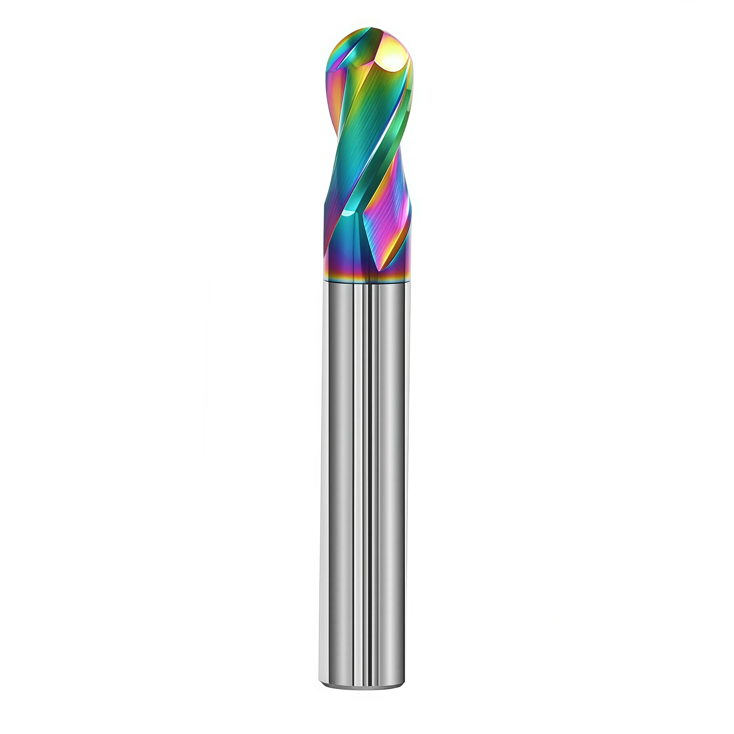
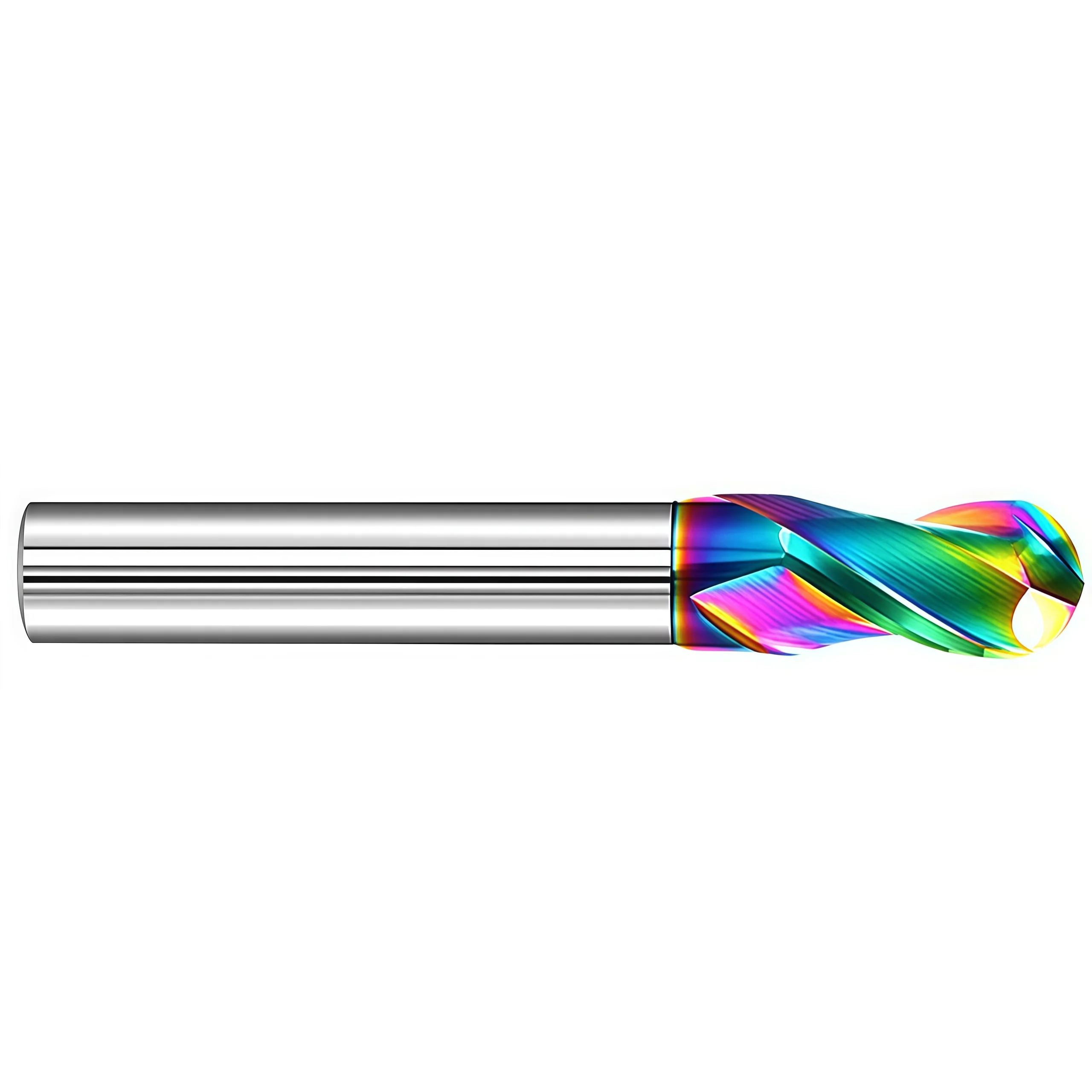

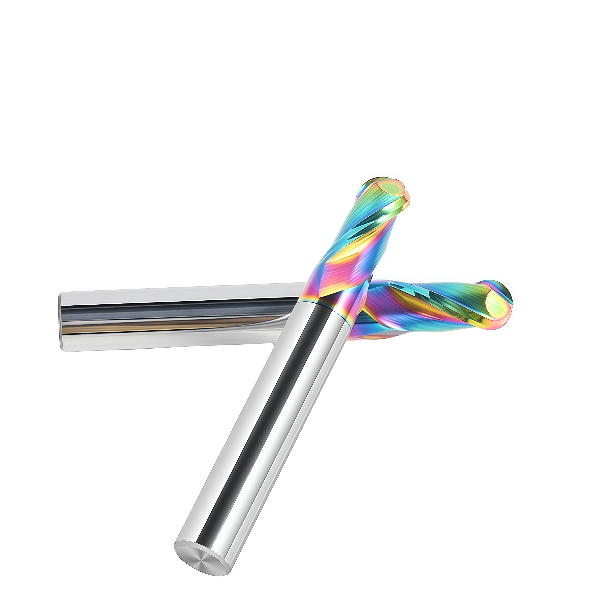

DLC-Coated 2-Flute Solid Carbide Ball Nose End Mill for Aluminum
This 2-flute DLC coated solid carbide ball nose end mill delivers smooth cutting, low adhesion, and excellent surface finish for high-speed aluminum machining applications.
⚙️ Configuraciones de productos
*Tool Type: Ball nose end mill
*Flute Count: 2 Flauta
*Recubrimiento: DLC (Diamond-Like Carbon)
*Materiales de aplicación: Aluminio, aleaciones de aluminio, metales no ferrosos
*Machining Type: Profiling / finishing / engraving
*Gama de diámetros: Multiple diameters available for different machining requirements
*Ángulo de la hélice: Optimized helix design for smooth chip evacuation
*Substrate: Ultra-fine grain solid carbide for high rigidity and wear resistance
*Personalización: Custom diameter, flute length, overall length and specifications available
Calidad constante
Consistent geometry across repeat orders.
Pedidos flexibles
Small batches and mixed sizes available.
OEM Support
Custom marking, labels and packaging.
Herramientas estándar y personalizadas
Standard sizes and custom configurations.
DLC Carbide Ball Nose End Mill Overview
This DLC-coated 2-flute solid carbide ball nose end mill is designed for 3D contouring, profiling and finishing in aluminum. The DLC coating reduces adhesion, while the 2-flute geometry supports smooth chip evacuation. Custom sizes, coating and OEM branding are available.
Key Configuration
Full-Radius Ball Nose
Maintains smooth cutting on curved surfaces, cavities, fillets and 3D profiles.
Wide Two-Flute Chip Space
Improves chip clearance in high-speed aluminum contouring and cavity machining.
Low-Friction DLC Surface
Reduces chip adhesion, built-up edge and friction when machining aluminum.
Key Product Advantages
Smooth 3D Toolpaths
Supports smooth cutting on curved and free-form surfaces.
Efficient Chip Evacuation
Two wide flutes improve chip evacuation and reduce recutting.
Reduced Aluminum Adhesion
DLC coating helps reduce built-up edge in non-ferrous machining.
Non-Ferrous Application
Diseñado para aluminum, copper, brass and other non-ferrous materials.
Milling Operations
Mold Cavity Milling
Profile Milling
Semi-Finishing
Surface Finishing
Workpiece Material Compatibility
| MATERIAL GROUP | EXAMPLES | APPLICATION LEVEL |
|---|---|---|
| N Aluminum | Wrought, cast and high-silicon aluminum alloys | Primary application |
| N Copper Alloys | Copper and selected brass alloys | Confirm alloy and cutting condition |
| N Other Non-Ferrous | Compatible soft and non-ferrous materials | Application review required |
Product Details & Milling Demonstration
Product-image positions and a machining demonstration for the DLC-coated 2-flute solid carbide ball nose end mill for aluminum.
Tool Nomenclature & Dimensions
Standard dimensions and configurations for the DLC-coated 2-flute ball nose end mill for aluminum. All dimensions are in millimeters.
Technical Configuration
| TECHNICAL ITEM | SPECIFICATION |
|---|---|
| Tipo de herramienta | Solid carbide ball nose end mill |
| End Profile | Ball Nose / Full Radius |
| Recuento de flautas | 2 flautas |
| Material de la herramienta | Sub-Micron Solid Carbide |
| Revestimiento | DLC — Diamond-Like Carbon |
| Ángulo de la hélice | 35°–40° |
| Shank Tolerance | h6 |
| Primary Materials | Aluminum / Aluminum Alloys / Compatible Non-Ferrous Materials |
| Primary Operations | 3D contouring, curved-surface machining, cavity milling, profiling and fine finishing |
| Dirección de corte | Corte a derechas |
| Coolant Method | Air Blow / Oil Mist / External Coolant According to Application |
Standard Size Matrix
Standard sizes by ball radius, flute length, shank diameter and overall length. Custom sizes are available by drawing.| SPECIFICATION | R | DC / D | APMX / L1 | DCON / d | OAL / L | FLUTES |
|---|---|---|---|---|---|---|
| R0.5×2×D4×50L | 0.5 | 1 | 2 | 4 | 50 | 2 |
| R0.75×3×D4×50L | 0.75 | 1.5 | 3 | 4 | 50 | 2 |
| R1×4×D4×50L | 1 | 2 | 4 | 4 | 50 | 2 |
| R1.25×5×D4×50L | 1.25 | 2.5 | 5 | 4 | 50 | 2 |
| R1.5×6×D3×50L | 1.5 | 3 | 6 | 3 | 50 | 2 |
| R1.5×6×D3×75L | 1.5 | 3 | 6 | 3 | 75 | 2 |
| R1.5×6×D3×100L | 1.5 | 3 | 6 | 3 | 100 | 2 |
| R1.5×6×D4×50L | 1.5 | 3 | 6 | 4 | 50 | 2 |
| R1.5×6×D6×50L | 1.5 | 3 | 6 | 6 | 50 | 2 |
| R1.75×7×D4×50L | 1.75 | 3.5 | 7 | 4 | 50 | 2 |
| R2×8×D4×50L | 2 | 4 | 8 | 4 | 50 | 2 |
| R2×8×D4×75L | 2 | 4 | 8 | 4 | 75 | 2 |
| R2×8×D4×100L | 2 | 4 | 8 | 4 | 100 | 2 |
| R2.5×10×D5×50L | 2.5 | 5 | 10 | 5 | 50 | 2 |
| R2.5×10×D5×75L | 2.5 | 5 | 10 | 5 | 75 | 2 |
| R2.5×10×D5×100L | 2.5 | 5 | 10 | 5 | 100 | 2 |
| R2.5×10×D6×50L | 2.5 | 5 | 10 | 6 | 50 | 2 |
| R3×12×D6×50L | 3 | 6 | 12 | 6 | 50 | 2 |
| R3×12×D6×75L | 3 | 6 | 12 | 6 | 75 | 2 |
| R3×12×D6×100L | 3 | 6 | 12 | 6 | 100 | 2 |
| R3×12×D6×150L | 3 | 6 | 12 | 6 | 150 | 2 |
| R3.5×14×D8×60L | 3.5 | 7 | 14 | 8 | 60 | 2 |
| R4×16×D8×60L | 4 | 8 | 16 | 8 | 60 | 2 |
| R4×16×D8×75L | 4 | 8 | 16 | 8 | 75 | 2 |
| R4×16×D8×100L | 4 | 8 | 16 | 8 | 100 | 2 |
| R4×16×D8×150L | 4 | 8 | 16 | 8 | 150 | 2 |
| R4.5×18×D10×75L | 4.5 | 9 | 18 | 10 | 75 | 2 |
| R5×20×D10×75L | 5 | 10 | 20 | 10 | 75 | 2 |
| R5×20×D10×100L | 5 | 10 | 20 | 10 | 100 | 2 |
| R5×20×D10×150L | 5 | 10 | 20 | 10 | 150 | 2 |
| R5.5×22×D12×75L | 5.5 | 11 | 22 | 12 | 75 | 2 |
| R6×24×D12×75L | 6 | 12 | 24 | 12 | 75 | 2 |
| R6×24×D12×100L | 6 | 12 | 24 | 12 | 100 | 2 |
| R6×24×D12×150L | 6 | 12 | 24 | 12 | 150 | 2 |
| R6.5×26×D14×100L | 6.5 | 13 | 26 | 14 | 100 | 2 |
| R7×28×D14×80L | 7 | 14 | 28 | 14 | 80 | 2 |
| R7×28×D14×100L | 7 | 14 | 28 | 14 | 100 | 2 |
| R7×28×D14×150L | 7 | 14 | 28 | 14 | 150 | 2 |
| R8×32×D16×100L | 8 | 16 | 32 | 16 | 100 | 2 |
| R8×32×D16×150L | 8 | 16 | 32 | 16 | 150 | 2 |
| R9×36×D18×100L | 9 | 18 | 36 | 18 | 100 | 2 |
| R9×36×D18×150L | 9 | 18 | 36 | 18 | 150 | 2 |
| R10×40×D20×100L | 10 | 20 | 40 | 20 | 100 | 2 |
| R10×40×D20×150L | 10 | 20 | 40 | 20 | 150 | 2 |
DLC Ball Nose End Mill Application Guidance
- 3D Finishing: Set step-over by ball radius and required finish.
- Tool Center: Use suitable tool inclination where possible.
- Chip Removal: Use air blast or coolant to reduce chip recutting.
- Extended Reach: Reduce engagement and feed with longer overhang.
- Toolholding: Use a low-runout holder with minimal overhang.
- Material: Best suited for aluminum and non-ferrous materials.
DLC-Coated Ball Nose End Mill Customization
| PARAMETER | MANUFACTURING CAPABILITIES |
|---|---|
| Ball Radius & Cutting Diameter | Standard ball radii from R0.5 to R10, corresponding to Ø1–Ø20 mm cutting diameters; intermediate and drawing-defined sizes can be reviewed |
| Recuento de flautas | Standard 2-flute geometry with wide chip space for efficient evacuation of aluminum chips during high-speed contouring and cavity machining |
| Longitud de flauta | Standard or drawing-defined flute lengths selected according to the cutting diameter, machining depth and required tool rigidity |
| Neck & Reach Configuration | Straight-neck and relieved-neck configurations can be reviewed for deep cavities, recessed profiles and restricted-access machining |
| Longitud total | Standard, long-series and drawing-defined overall lengths available after checking tool overhang and setup rigidity |
| Shank Configuration | Precision cylindrical shank with standard h6 tolerance; custom shank diameter and clamping length can be reviewed according to the drawing |
| Ángulo de la hélice | Standard 35°–40° helix range, with the final geometry selected according to the aluminum grade, chip formation and finishing requirement |
| Ball-Nose Geometry | Precision-ground full-radius profile for 3D contours, mold cavities, fillets and curved surfaces, with profile accuracy matched to the required finish |
| Flute & Edge Finish | Sharp cutting edges and a smooth flute surface can be optimized to reduce cutting resistance, chip adhesion and built-up edge in aluminum |
| DLC Coating | Low-friction DLC coating for improved wear resistance and reduced aluminum adhesion; coating suitability is confirmed according to the workpiece alloy |
| Milling Application | Geometry can be reviewed for 3D contouring, curved-surface machining, cavity milling, profiling, detail machining and fine surface finishing |
| Dimensional Tolerance | Drawing-defined requirements for ball radius, cutting diameter, flute length, neck diameter, shank diameter, overall length, runout and profile accuracy |
Servicios de fabricación personalizada y marca propia
OEM manufacturing and private-label supply options are available for industrial distributors, tooling brands and repeat-production customers. Laser identification, label content, protective packaging and coating presentation can be configured according to the approved product specification and order requirements.

Technical Workflow
A structured review process is used to confirm standard, customized and private-label square end mill requirements before production.
Inquiry
Submit the material, hardness, milling operation, dimensions, tolerance and quantity.
Engineering
Review flute geometry, helix angle, edge preparation, coating, ap and ae.
Commercial
Confirm quotation, MOQ, sample requirements, production schedule and delivery terms.
Production
CNC grinding, end-face formation, edge preparation, coating and laser marking.
Quality Control
Inspect diameter, flute length, shank, runout, square-end geometry and cutting edges.
Quality, Inspection & Delivery
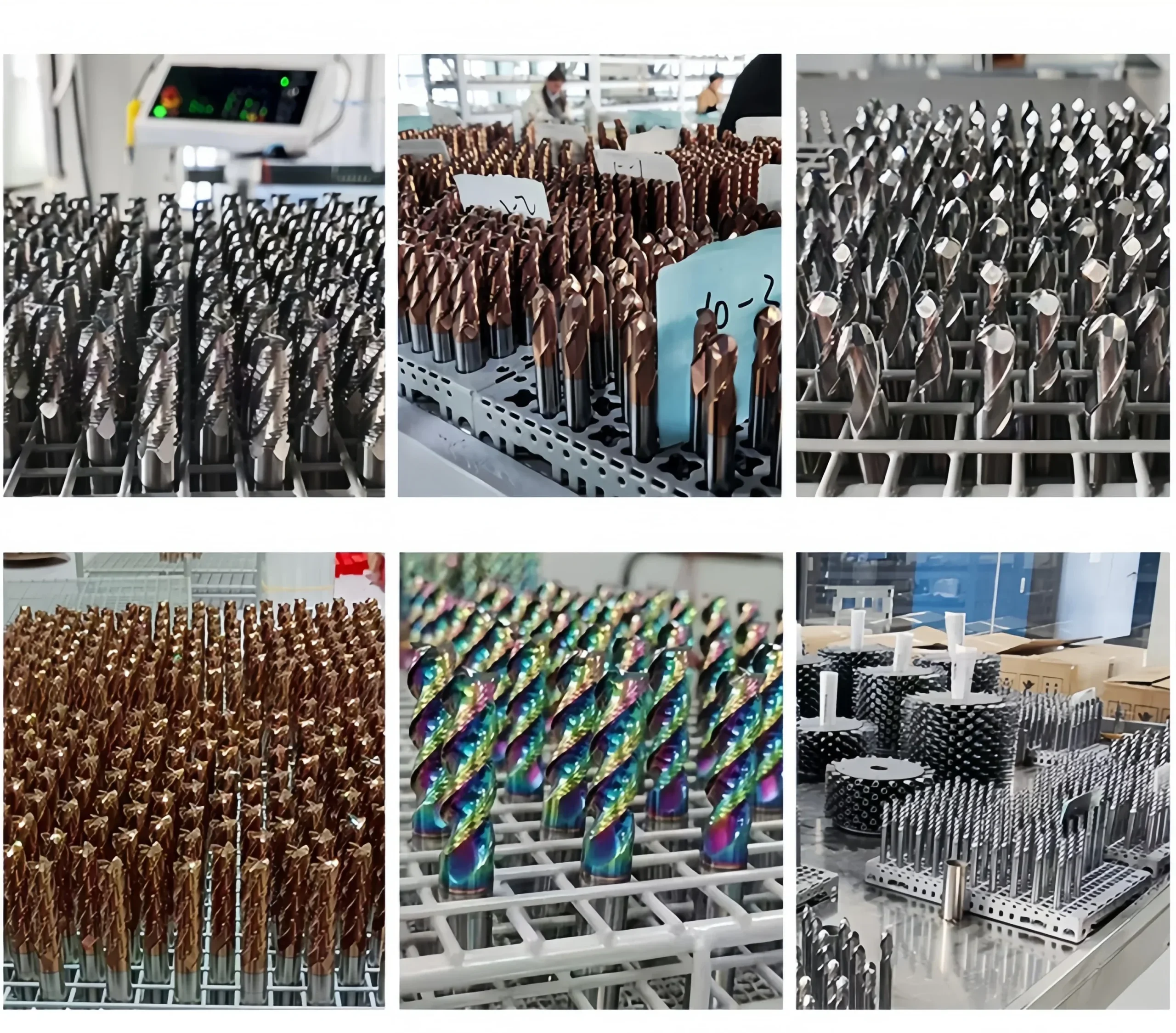
Nuestra solid carbide square end mills are checked through material verification, precision grinding and final inspection. Key dimensions, cutting edges, coating and identification are verified before packing.
Three-Stage Quality Control
Inspection checkpoints are arranged around the manufacturing process to support dimensional consistency and repeat-order control.
Incoming Material Control
Carbide substrate grade, blank dimensions and supplied material information are checked against the production requirement.
In-Process Grinding Control
Cutting diameter, flute geometry, flute length, square-end profile and shank dimensions are monitored during CNC grinding.
Final Tool Inspection
Finished tools are reviewed for specified dimensions, runout, cutting-edge condition, coating appearance, marking and packing identification.
Protective Packaging Process
Finished end mills are protected to reduce contact between cutting edges and to support clear product identification during storage and transportation.

Bulk-Order & Export Packaging
Bulk shipments can be arranged with reinforced cartons, protective wrapping, palletized loading or export cases according to order quantity, shipment weight and agreed transportation requirements.

Product & Application FAQs
Answers to common questions about selecting and applying the DLC-Coated 2-Flute Solid Carbide Ball Nose End Mill for Aluminum.
What materials is this ball nose end mill designed to machine?
What operations are suitable for the ball-nose profile?
Why is a 2-flute design used for aluminum machining?
How can built-up edge and aluminum adhesion be controlled?
Can this tool be used for finishing 3D surfaces?
What is the benefit of DLC coating?
Ordering & Customization FAQs
Information for distributors, tooling brands and customers requesting standard or application-specific ball-nose configurations.
What standard sizes are available?
Can non-standard dimensions or geometry be manufactured?
Are OEM marking and private-label packaging available?
What information is required for an accurate quotation?
Technical Downloads
Use the following references for product selection and starting cutting-data review.
Solid Carbide End Mill Catalog
Review related ball-nose, square-end, corner-radius and application-specific end mill series.
End Mill Speeds & Feeds Guide
Access reference starting parameters for application review and controlled machining trials.
Need Sizes, Pricing or Custom Options?
Send us the required tool type, sizes, quantities, workpiece material and any OEM or custom requirements. We will confirm suitable specifications, availability, lead time and quotation details.
Drawings, size lists and reference photos are welcome.