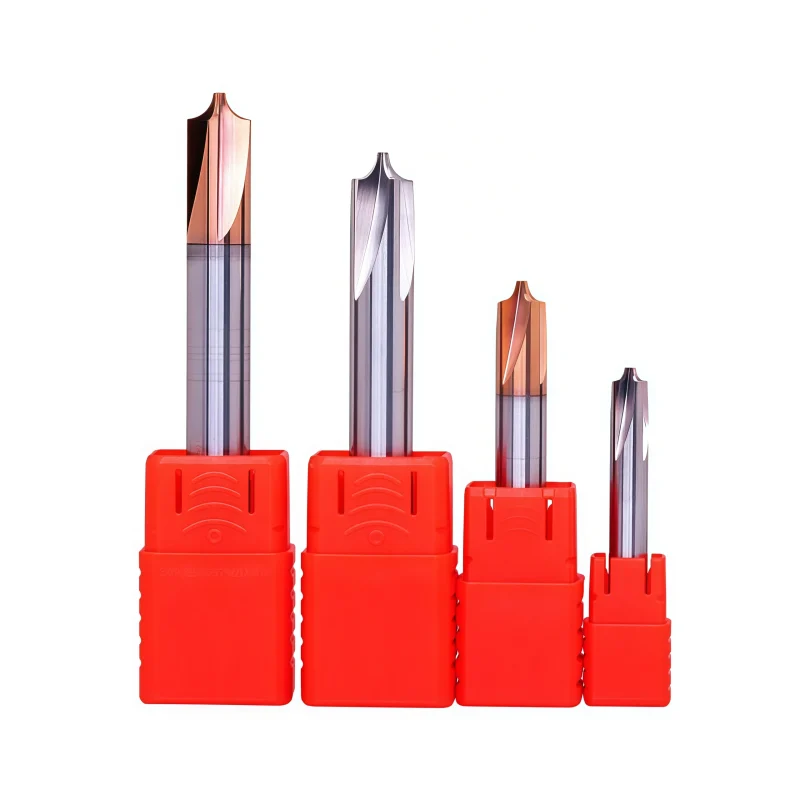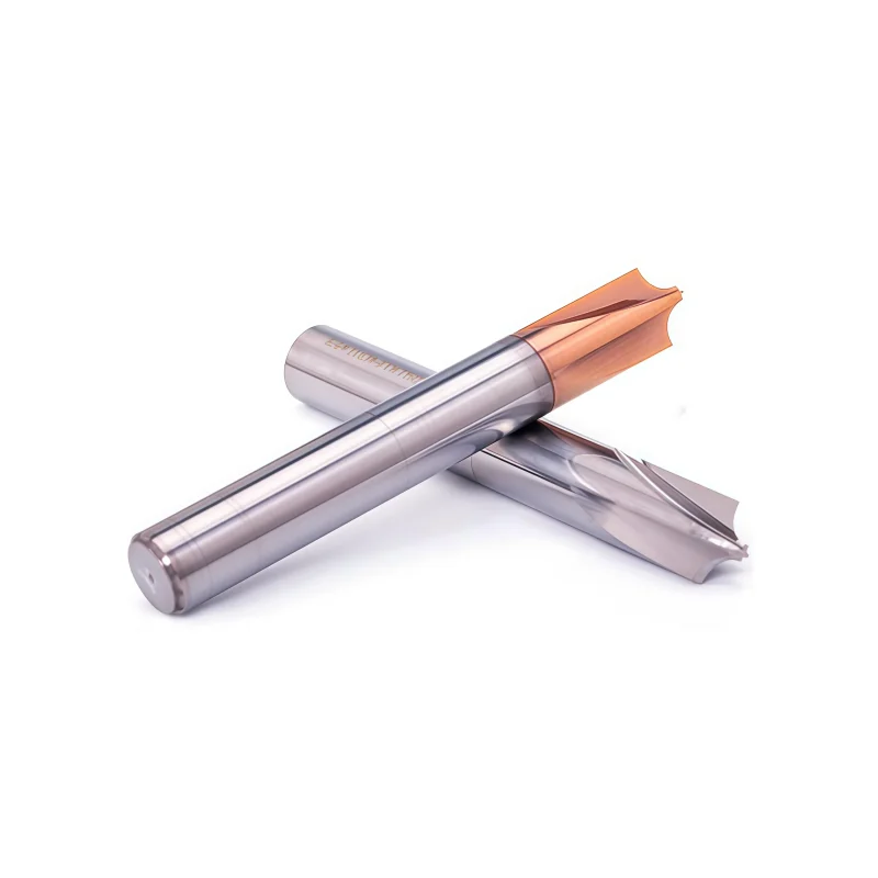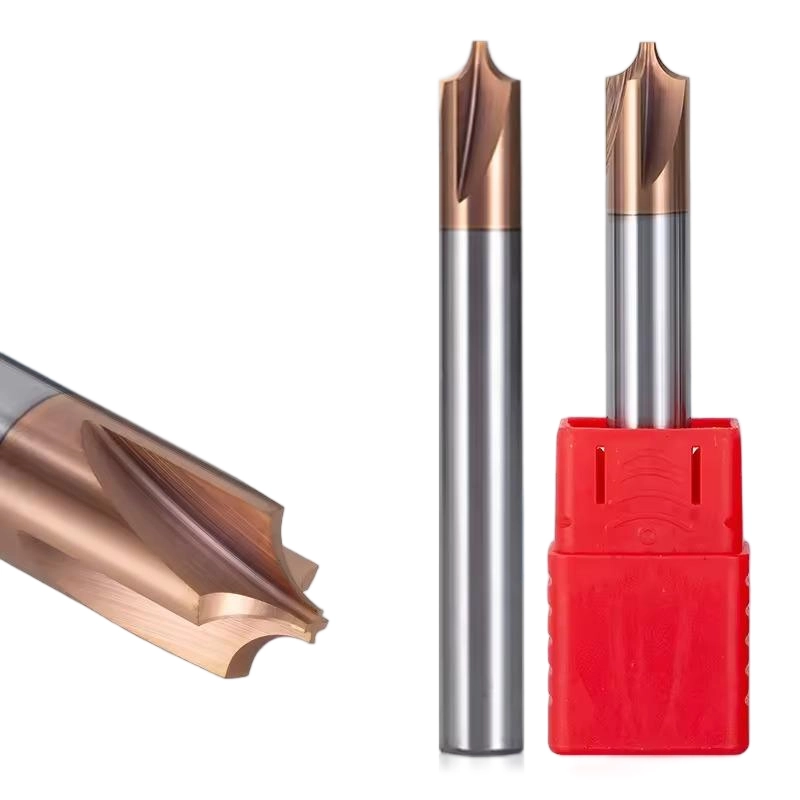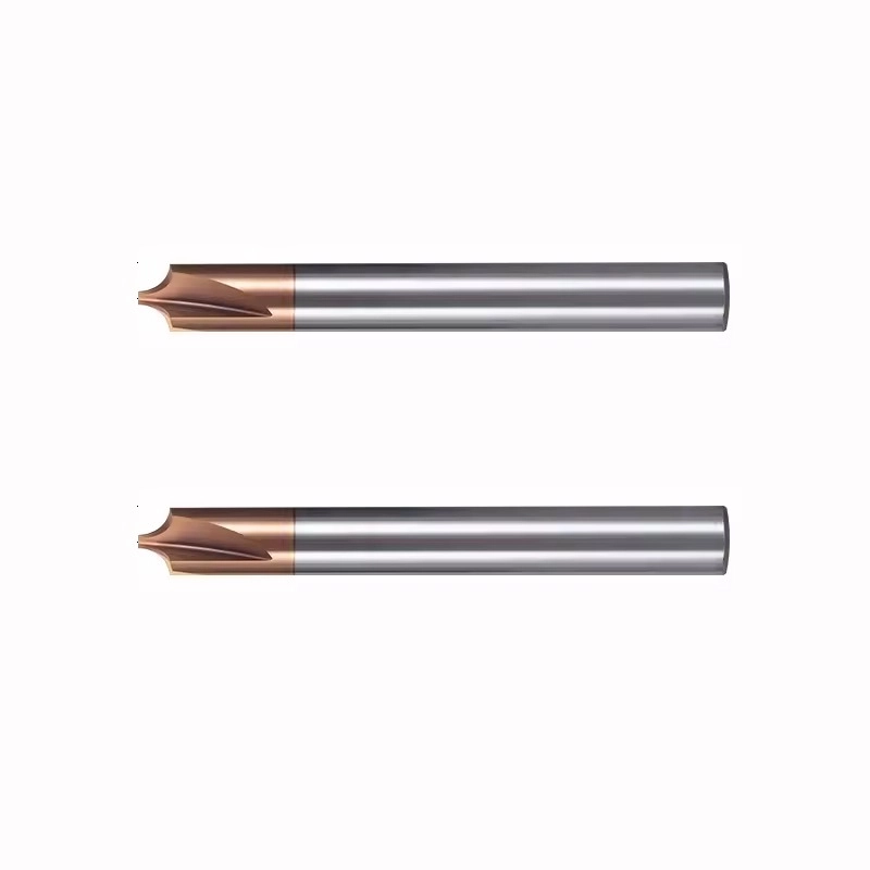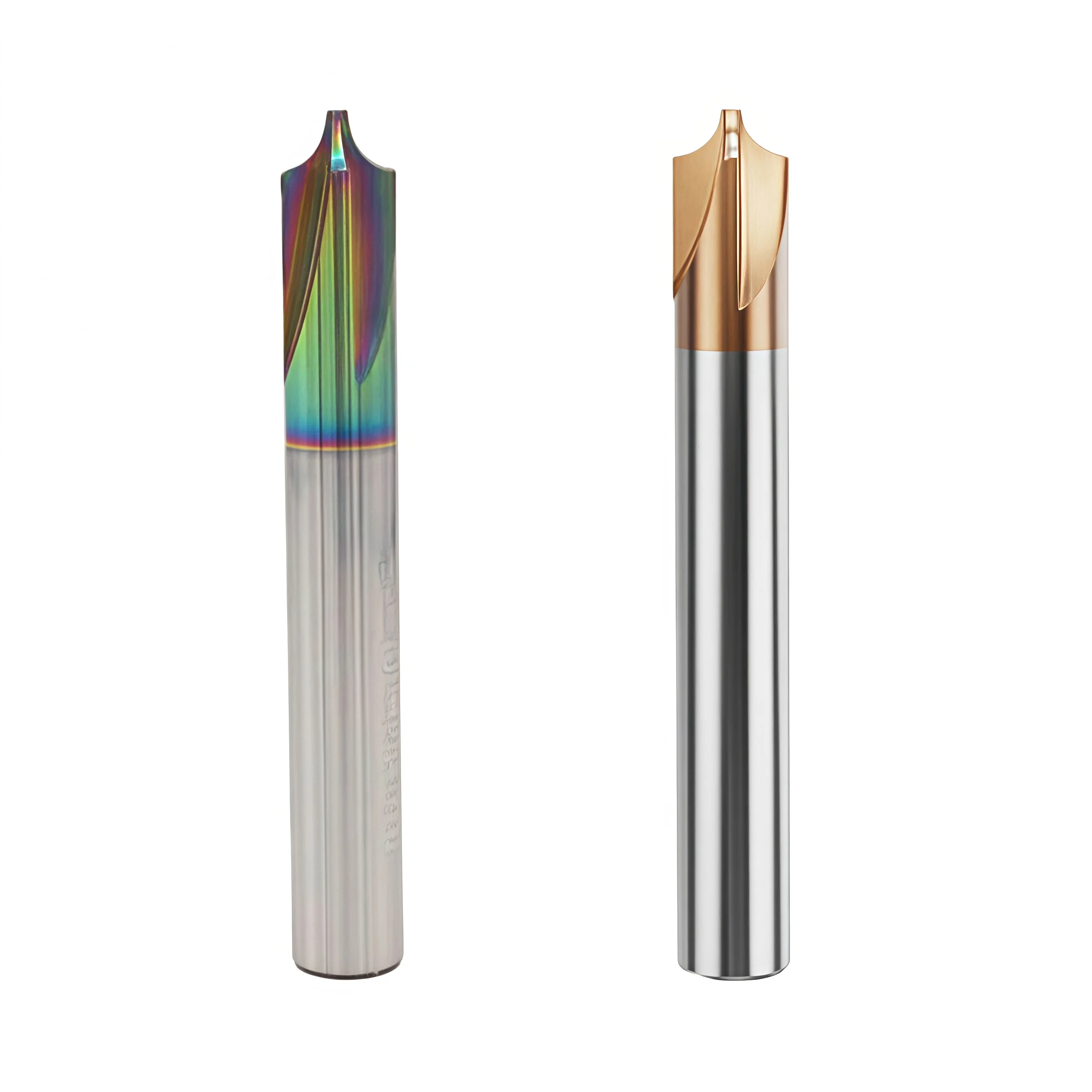
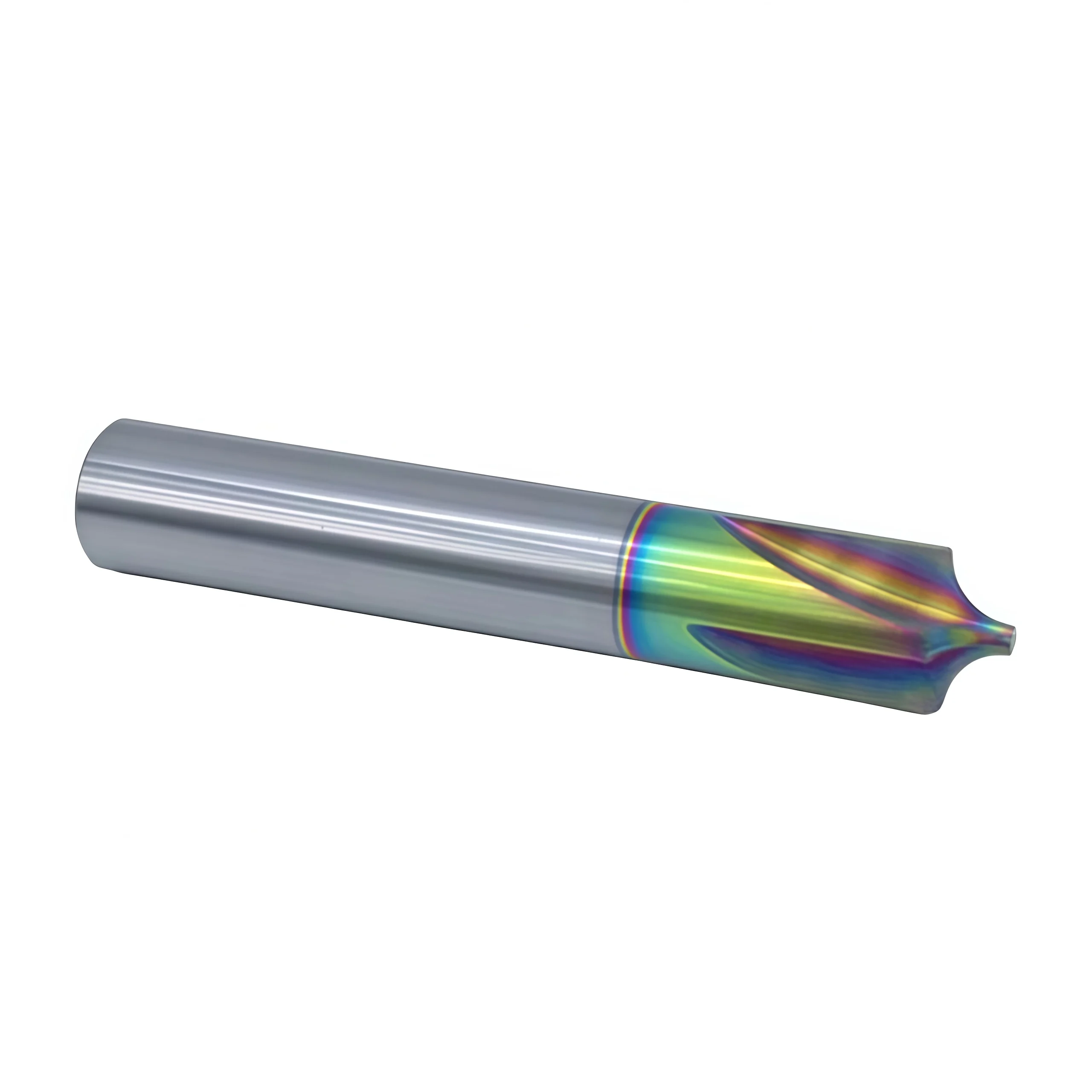
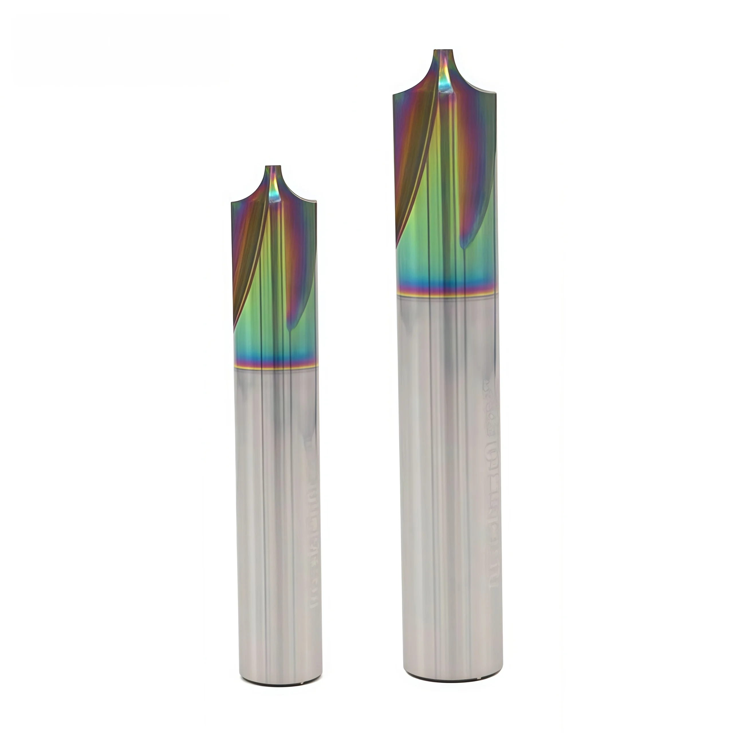
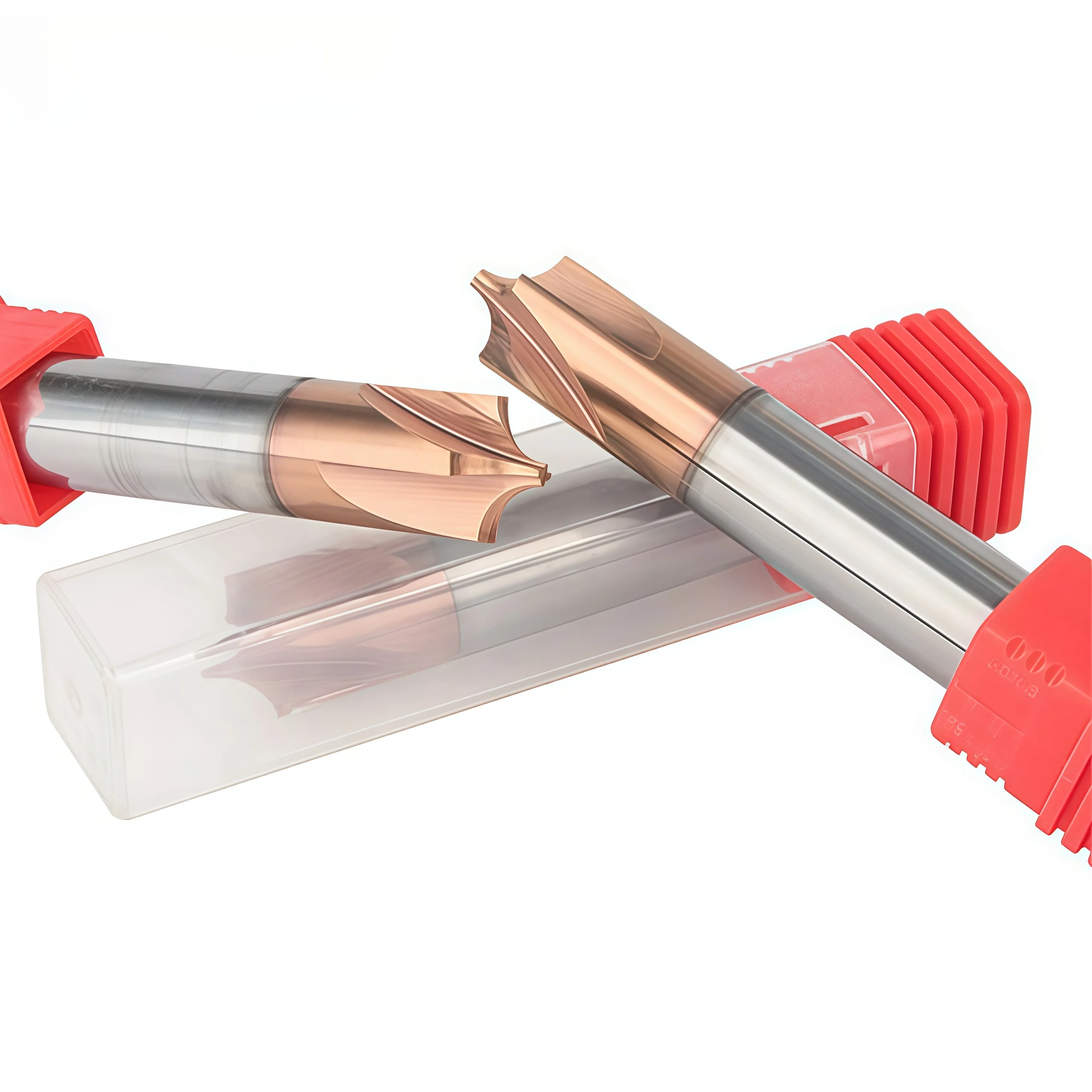
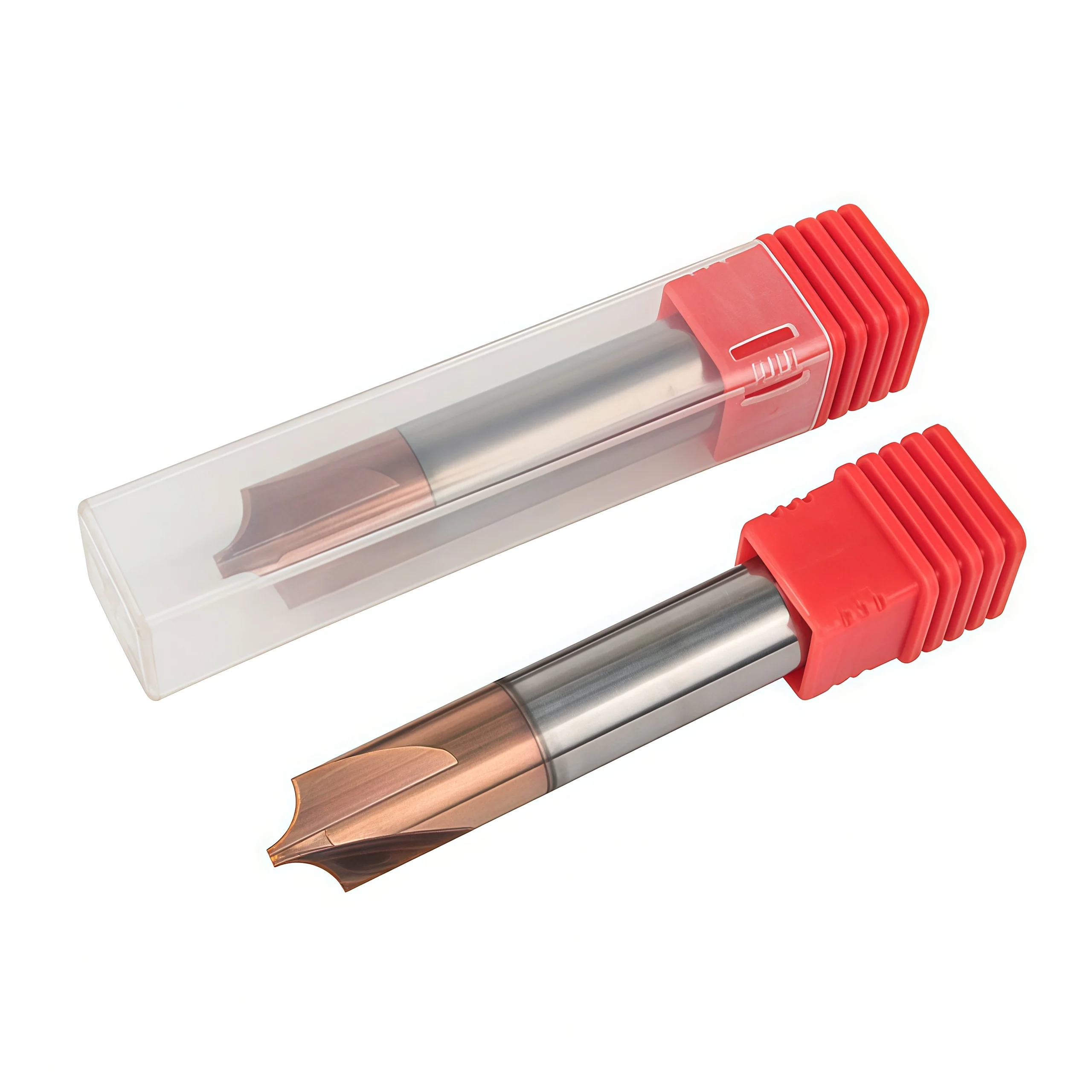
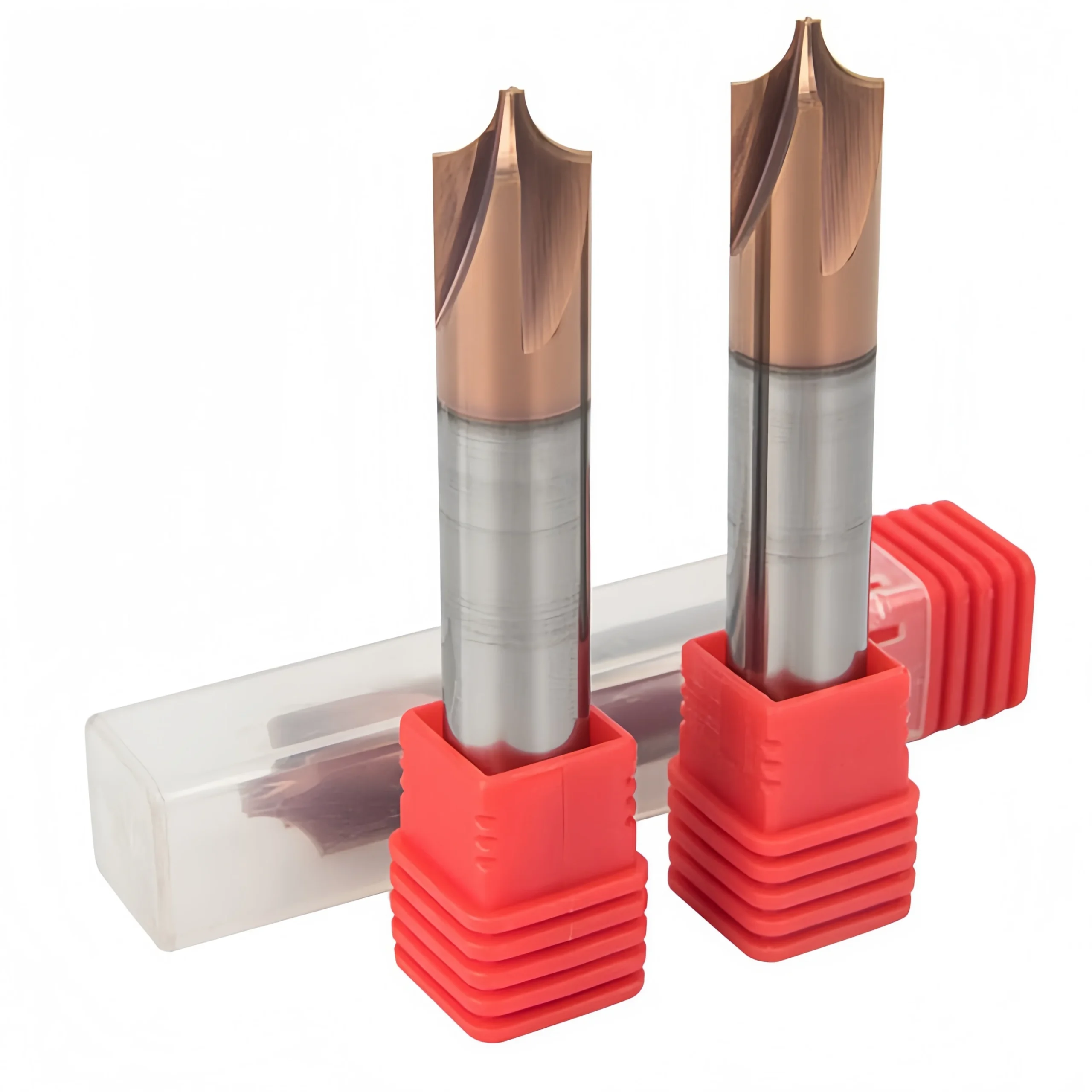
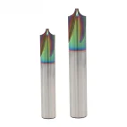
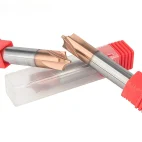
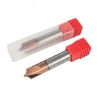
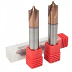
4-Flute Solid Carbide Internal Corner-Rounding and Chamfering End Mill
- ◆Precision-ground radius profile provides accurate and repeatable edge geometry
- ◆4-flute balanced design improves rigidity and surface finish
- ◆Solid carbide construction provides excellent edge strength and wear resistance
Custom radius, cutting diameter, flute length, shank size, coating, laser marking and packaging are available for OEM and ODM orders.
Tutarlı Kalite
Tekrarlanan siparişlerde tutarlı geometri.
Esnek Siparişler
Küçük partiler ve farklı boyutlarda seçenekler mevcuttur.
OEM Desteği
Özel işaretleme, etiketler ve ambalajlama.
Standart ve Özel
Standart boyutlar ve özel konfigürasyonlar.
Combination Carbide Internal End Mill Overview
This 4-flute solid carbide combination end mill integrates radius-forming and chamfering geometry into one tool for components that require both rounded transitions and edge chamfers. The combined cutting profile allows compatible radius and chamfer features to be machined within one tooling setup, making the cutter suitable for mold cavities, precision mechanical components, valve bodies and other parts with multi-feature edge geometry. The 4-flute solid carbide construction provides a rigid cutting platform, while radius, chamfer angle, tool dimensions and coating can be selected according to the workpiece material and component drawing.
Combination Profile
4 Flutes
R1–R6 mm
30° / 45° / 60°
Combination Radius & Chamfer Geometry
Radius-Forming Profile
The formed cutting section produces the specified radius or rounded transition according to the component geometry and required profile.
Integrated Chamfering Edge
The chamfering section can be configured for 30°, 45°, 60° or drawing-defined edge geometry where radius and chamfer features are required together.
Single-Tool Combination Machining
Combining the radius and chamfer features in one cutter can reduce separate tooling operations when the component geometry and machining sequence are suitable.
Application-Specific Advantages
Combined Operations
Radius forming and chamfering can be integrated into one application-specific cutting profile.
4-Flute Geometry
Four cutting edges support repeated engagement during combined profile machining.
Flexible Chamfer Geometry
30°, 45° and 60° chamfer configurations cover common edge-forming requirements.
Custom Combination Profile
Radius, chamfer angle, feature position, diameter and length can be reviewed from drawings.
Recommended Machining Operations
RECOMMENDED
RECOMMENDED
SUITABLE
SUITABLE
Workpiece Material Compatibility
| MATERIAL GROUP | BAŞVURU | LEVEL |
|---|---|---|
| P Mold & Tool Steel | Combination radius and chamfer machining | Primary |
| M Stainless Steel | Application-specific coating and cutting conditions required | Application Review |
| N Aluminum Alloys | Material-specific sharp geometry and coating configuration | Suitable |
| Engineering Plastics | Application-specific profile and cutting-edge geometry | Application Review |
Product & Machining Video
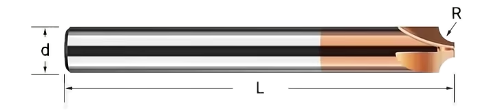
Tool Nomenclature & Dimensions
Reference dimensions for the 4-flute solid carbide combination corner-rounding and chamfering end mill. The radius, chamfer geometry and their axial relationship should be confirmed together because both cutting features are integrated into one tool. A component drawing is recommended for non-standard combination profiles.
Technical Configuration
| PARAMETRE | REFERANS KURULUMU |
|---|---|
| Alet Tipi | Combination Corner-Rounding & Chamfering End Mill |
| Alet Malzemesi | Solid Carbide |
| Flüt Sayısı | 4 Flutes |
| Primary Function | Radius Forming + Edge Chamfering |
| Standard 4-Flute Radius Range | R1 / R1.5 / R2 / R2.5 / R3 / R4 / R5 / R6 mm |
| Smaller Radius Options | Smaller radii can be reviewed separately according to flute configuration and application requirements |
| Chamfer Angles | 30° / 45° / 60°; custom angles subject to technical review |
| Çap Aralığı | Ø3–Ø16 mm reference product range |
| Heliks Geometrisi | 38°–42° variable-helix reference configuration |
| Kaplama Seçenekleri | TiAlN / AlTiN / DLC — selected according to workpiece material and application |
| Başvuru Belgeleri | Mold Steel / Stainless Steel / Aluminum Alloys / Engineering Plastics according to selected configuration |
| Özelleştirme | Radius, chamfer angle, chamfer width, feature position, cutter dimensions, shank, overall length and coating can be reviewed according to drawings. |
Standard 4-Flute Radius Size Matrix
Reference 4-flute dimensions for the radius-forming section. The chamfer geometry should be confirmed separately according to the required combination profile.
| SPECIFICATION | RADIUS R | SHANK DIA. d | OVERALL LENGTH L | FLÜT |
|---|---|---|---|---|
| R1 × 4 × 50 × 4T | 1 | 4 | 50 | 4 |
| R1.5 × 6 × 50 × 4T | 1.5 | 6 | 50 | 4 |
| R2 × 6 × 50 × 4T | 2 | 6 | 50 | 4 |
| R2.5 × 8 × 50 × 4T | 2.5 | 8 | 50 | 4 |
| R3 × 8 × 50 × 4T | 3 | 8 | 50 | 4 |
| R4 × 10 × 60 × 4T | 4 | 10 | 60 | 4 |
| R5 × 12 × 75 × 4T | 5 | 12 | 75 | 4 |
| R6 × 14 × 75 × 4T | 6 | 14 | 75 | 4 |
Combination Machining Guidance
- Profile Matching: Confirm both the radius and chamfer dimensions from the component drawing before selecting or manufacturing the cutter.
- Axial Position: The relationship between the radius and chamfer features depends on accurate cutter positioning and the axial spacing built into the tool profile.
- Toolholding: Use a low-runout precision holder and the shortest practical overhang to maintain profile consistency.
- Material Configuration: Select cutting-edge preparation and coating according to the actual steel, stainless, aluminum or plastic grade.
- Custom Tools: For non-standard combination profiles, provide a component drawing showing the radius, chamfer angle, chamfer width and axial feature positions.
Combination Internal End Mill Customization
Radius size, chamfer angle, chamfer width, combination-profile geometry, feature position, cutter dimensions, shank configuration, overall length, cutting-edge preparation and coating can be configured according to the component drawing and machining application. Standard 4-flute configurations cover R1–R6 mm radius sizes, while 30°, 45° and 60° chamfer angles are available as reference options. Non-standard combination profiles can be reviewed according to the workpiece material, required radius-to-chamfer relationship, machining depth, feature clearance and dimensional requirements.
| PARAMETRE | ÜRETİM KAPASİTELERİ |
|---|---|
| Radius Size | Current standard 4-flute configurations include R1, R1.5, R2, R2.5, R3, R4, R5 and R6 mm. Smaller or non-standard radii can be reviewed separately according to the required profile and flute configuration. |
| Pah Açısı | 30°, 45° and 60° chamfer angles are available as reference configurations. Non-standard angles can be reviewed according to the component drawing and required edge geometry. |
| Chamfer Width | Chamfer width can be configured according to the finished component requirement, cutter diameter and available profile length. |
| Combination Profile | Radius-forming and chamfering sections can be integrated into one cutting profile. The relationship between both features should be defined from the component drawing for accurate tool design. |
| Feature Position & Spacing | Axial position and spacing between the radius and chamfer features can be reviewed according to the workpiece geometry, machining depth and required transition position. |
| Flüt Sayısı | Standard 4-flute solid carbide configuration for combination profile machining. |
| Cutter Diameter | Reference product diameter range is Ø3–Ø16 mm. Non-standard cutter dimensions can be reviewed according to the required radius, chamfer geometry and component clearance. |
| Heliks Geometrisi | A 38°–42° variable-helix configuration is available as a reference design. Final helix geometry can be selected according to workpiece material, chip evacuation and cutting engagement. |
| Şaft Yapısı | Precision cylindrical shank dimensions can be selected according to tool size, holder compatibility, clamping length and required machining reach. |
| Toplam Uzunluk | Standard and drawing-defined overall lengths can be reviewed according to machining depth, toolholder clearance and required tool rigidity. |
| Cutting-Edge Preparation | Radius-forming edges, chamfering edges, relief geometry and edge preparation can be matched to the workpiece material, cutting load and required profile finish. |
| Kaplama Seçimi | TiAlN, AlTiN or DLC configurations can be reviewed according to workpiece material and machining conditions. Steel and stainless-steel applications normally require a different coating strategy from aluminum and other non-ferrous materials. |
| İş Parçası Malzemesi | Configurations can be reviewed for mold steel, stainless steel, aluminum alloys and selected engineering plastics. Cutting geometry and coating should be matched to the actual material rather than using one universal configuration. |
| Machining Application | Suitable configurations can be developed for combined radius forming, edge chamfering, profile finishing, cavity-edge machining and other multi-feature operations. |
| Profile & Dimensional Tolerance | Drawing-defined requirements can be reviewed for radius geometry, chamfer angle, chamfer width, feature spacing, cutter diameter, shank diameter, overall length and tool runout. |
| Replacement Tool Matching | Existing combination cutters can be reviewed from a detailed tool drawing or physical sample when an equivalent or replacement specification is required. |
| OEM & Private Label | Laser marking, custom tool codes, private labels and packaging can be reviewed for distributors and OEM customers according to tool dimensions and order quantity. |
OEM ve Özel Etiket Hizmetleri
Endüstriyel distribütörler, alet markaları ve düzenli üretim yapan müşteriler için OEM üretimi ve özel etiketli tedarik seçenekleri mevcuttur. Lazerle işaretleme, etiket içeriği, koruyucu ambalaj ve kaplama sunumu, onaylanmış ürün spesifikasyonuna ve sipariş gereksinimlerine göre yapılandırılabilir.

Lazer Kazıma
Özel logolar, takım kodları, kesme boyutları, kaplama tanımları ve parti numaraları, mevcut şaft alanına göre işaretlenebilir.
Özel Etiketler ve Ambalajlar
Tek tek koruyucu tüpler, ürün etiketleri, teknik özellik detayları, renkli ambalaj tüpleri ve özel markalı ambalajlar incelenebilir.
Ticari Şartlar
Minimum sipariş miktarı (MOQ), numune değerlendirmesi, özel boyut denemeleri, tekrar siparişler ve planlı tedarik programları, seçilen konfigürasyona göre teyit edilir.
Teknik İş Akışı
Üretim öncesinde standart, özel tasarım ve özel markalı kare uçlu frezelerin gereksinimlerini doğrulamak için yapılandırılmış bir inceleme süreci uygulanmaktadır.
Sorgulama
Malzeme, sertlik, frezeleme işlemi, boyutlar, tolerans ve miktarı belirtiniz.
Mühendislik
Flüt geometrisini, sarmal açısını, kenar hazırlığını, kaplamayı, ap ve ae değerlerini gözden geçirin.
Ticari
Teklifi, minimum sipariş miktarını (MOQ), numune şartlarını, üretim takvimini ve teslimat koşullarını teyit edin.
Üretim
CNC taşlama, uç yüzey şekillendirme, kenar hazırlama, kaplama ve lazerle işaretleme.
Kalite Kontrolü
Çapı, oluk uzunluğunu, şaftı, eksantrikliği, kare uç geometrisini ve kesme kenarlarını kontrol edin.
Kalite, Denetim ve Teslimat
Katı karbür kare uçlu frezelerimiz, malzeme doğrulama, hassas taşlama, üretim süreci sırasında yapılan ölçümler ve son kontrol aşamalarıyla denetlenmektedir. Ana boyutlar, kare uç geometrisi, kesici kenar durumu, kaplama görünümü ve ürün tanımlaması, paketlemeden önce onaylanmış teknik şartnameye veya çizime göre incelenmektedir.

Üç Aşamalı Kalite Kontrolü
Üretim sürecinin çeşitli aşamalarına, boyutsal tutarlılığı sağlamak ve tekrar sipariş kontrolünü desteklemek amacıyla denetim noktaları yerleştirilmiştir.
Gelen Malzeme Kontrolü
Karbür alt tabaka kalitesi, ham parça boyutları ve tedarik edilen malzeme bilgileri, üretim gereksinimleriyle karşılaştırılarak kontrol edilir.
Üretim Sırasında Taşlama Kontrolü
CNC taşlama işlemi sırasında kesme çapı, oluk geometrisi, oluk uzunluğu, kare uç profili ve şaft boyutları izlenir.
Son Alet Kontrolü
Üretimi tamamlanmış takımlar, belirtilen boyutlar, eksantriklik, kesici kenar durumu, kaplama görünümü, işaretleme ve ambalaj tanımlaması açısından incelenir.
Temel Denetim Özellikleri
Denetim gereklilikleri, standart ürün şartnamesine veya onaylanmış özel çizime göre teyit edilir.
| DENETİM KONUSU | KONTROL ODAĞI | ONAY ESASLARI |
|---|---|---|
| Kesme Çapı (DC) | Çap ve boyut tutarlılığı | Standart teknik şartname veya onaylı çizim |
| Flüt Uzunluğu (APMX) | Etkili kesme uzunluğu | Onaylanmış ürün boyutu veya çizim gereksinimi |
| Şaft Çapı (DCON) | Sıkıştırma kesitinin boyutu ve yüzey durumu | Uygun şaft özellikleri |
| Toplam Uzunluk (OAL) | Toplam alet uzunluğu | Standart boyutlu matris veya onaylanmış çizim |
| Radyal Salgı | Kesme bölümü ile şaft arasındaki eşmerkezlilik | Kararlaştırılan denetim şartı |
| Kare Uçlu Geometri | Uç yüz profili, köşe durumu ve merkez kesim şekli | Seçilen araç yapılandırması |
| Flüt ve Heliks Profili | Flüt sayısı, sarmal şekli ve taşlama tutarlılığı | Onaylanmış üretim konfigürasyonu |
| Son Teknoloji ve Kaplama | Kenar durumu, gözle görülür kusurlar ve kaplama görünümü | Uygulamaya özgü üretim gereksinimi |
| İşaretleme ve Tanımlama | Uygun olduğu durumlarda alet kodu, boyutlar ve parti bilgileri | Onaylanmış sipariş ve paketleme özellikleri |
Ölçüm ve Parti İzlenebilirliği
Optik ölçüm sistemleri, takım kontrol ekipmanları ve uygun boyutsal ölçüm aletleri, kontrol edilecek özelliğe göre seçilir.
Optik Ölçüm
Belirtilen kesme özelliklerinin profil ve boyut incelemesi.
Çıkma Kontrolü
Kararlaştırılan ürün gereksinimlerine dayalı eşmerkezlilik incelemesi.
Kenar Denetimi
Uç yüzeyi, köşeler ve kesici kenarın durumuna ilişkin detaylı inceleme.
Parti Tanımlama
Tekrarlanan tedarik için gerekli olan yerlerde sipariş, ürün ve parti bilgileri birbiriyle ilişkilendirilmiştir.
Koruyucu Ambalajlama Süreci
Hazır uçlu frezeler, kesici kenarlar arasındaki teması azaltmak ve depolama ile nakliye sırasında ürünün net bir şekilde tanımlanmasını sağlamak amacıyla korunmaktadır.

Toplu Sipariş ve İhracat Ambalajı
Toplu sevkiyatlar, sipariş miktarına, sevkiyat ağırlığına ve kararlaştırılan nakliye şartlarına göre, takviyeli karton kutular, koruyucu ambalaj, paletli yükleme veya ihracat kasaları kullanılarak düzenlenebilir.

Teslimat Koordinasyonu
Üretimin tamamlanması, paketleme yöntemi ve sevkiyat düzenlemeleri, onaylanan siparişe göre teyit edilir. Kargo, hava, deniz veya müşteri tarafından belirlenen nakliye seçenekleri, sevkiyatın boyutuna ve varış noktasına göre değerlendirilebilir. Nihai teslim süresi, ürün özellikleri, miktar ve paketleme gereklilikleri onaylandıktan sonra teyit edilir.
Ürün ve Uygulama SSS'leri
Common questions about the 4-Flute Solid Carbide Combination Corner-Rounding and Chamfering End Mill for integrated radius forming, edge chamfering and profile machining.
What makes this a combination end mill?
What standard radius sizes are available in the 4-flute configuration?
Which chamfer angles are available?
What is the advantage of machining the radius and chamfer with one tool?
Which materials can this combination cutter machine?
How should I select the coating?
How is the relationship between the radius and chamfer controlled?
Sipariş ve Özelleştirme ile İlgili Sık Sorulan Sorular
Ordering information for distributors, tooling suppliers and OEM customers requiring standard or customized combination radius and chamfer cutters.
Can the radius and chamfer geometry be customized together?
Can you manufacture a replacement tool from an existing drawing or sample?
Can the diameter and overall length be customized?
OEM etiketleme ve özel markalı ambalajlama seçenekleri mevcut mu?
Genel olarak teslim süresi ne kadardır?
What information should I provide for quotation?
Teknik Dosyalar
Reference documents for solid carbide milling tool selection and machining-data review.
Katı Karbür Uçlu Freze Kataloğu
Review combination cutters and related solid carbide milling tool series.
Uçlu Freze Hızları ve İlerleme Hızları Kılavuzu
Access reference starting parameters for machining trials and application review.
Ölçüler, fiyatlar veya özel seçenekler mi arıyorsunuz?
Gerekli takım türünü, boyutlarını, miktarlarını, iş parçası malzemesini ve varsa OEM veya özel gereksinimleri bize iletin. Uygun teknik özellikleri, stok durumunu, teslim süresini ve fiyat teklifi ayrıntılarını size teyit edeceğiz.
Çizimler, boyut listeleri ve referans fotoğraflar memnuniyetle kabul edilir.