
Thread Milling vs Tapping: How to Choose the Right Tool
An M10 × 1.5 thread does not tell you which tool to buy.
For a repeat order on a proven production line, the right tap may be the straightforward choice. For a blind thread in an expensive component, or a job that needs controlled diameter adjustment, a thread mill may deserve a closer look. The thread designation is identical; the purchasing decision is not.
This thread milling vs tapping guide focuses on internal threads: how the tools differ, what to check before sourcing a replacement, and when a standard thread mill may not fit the job. Neither process is a universal upgrade over the other.
Quick comparison
Use this table to decide what to investigate first, not to approve a tool solely from a thread size.
| Decision point | Tapping | Thread milling |
|---|---|---|
| Established repeat production | Often a practical starting point | Compare against the existing accepted process |
| Machine requirement | Suitable tapping cycle and holder arrangement | Suitable helical interpolation and verified toolpath |
| Product identification | Thread size alone does not specify the tap | Pitch alone does not specify the cutter |
| Diameter adjustment | Review tap tolerance and process conditions | Radial adjustment is possible within process limits |
| Blind-hole selection | Check lead, chips and bottom clearance | Check cutter geometry, reach and entry clearance |
| Purchasing comparison | Match the complete model and application | Match the complete model and application |
Swipe to view all columns.
Tapping is particularly productive for many smaller-thread applications. Thread milling becomes worth evaluating when flexibility, size adjustment or process risk carries more weight. These are selection directions, not guaranteed outcomes.
For more cutting-tool comparison resources, visit the HY Tools คู่มือการเลือกเครื่องมือ.
For additional process references, see Sandvik Coromant’s tapping overview and thread milling overview.
How the Two Processes Work
A tap follows the hole axis. A thread mill rotates while following a helical path around the hole.
| Working principle | Tapping | Thread milling |
|---|---|---|
| Tool movement | Rotates relative to the workpiece and advances along the hole axis. | Rotates and moves around the hole on a coordinated helical path. |
| Material action | A cutting tap removes material; a forming tap displaces it without generating cutting chips. | Cutting edges remove material to generate the thread. |
| Thread diameter | The tap is sized for the specified nominal thread. | The cutter is smaller than the hole; the programmed path and cutting geometry establish the thread diameter. |
| Pitch and feed | The tap geometry defines pitch; axial movement must follow relative rotation at that pitch. | The cutter profile must suit the pitch; axial travel per circular revolution establishes thread lead. |
| Machine requirement | Suitable tapping synchronization and holder arrangement. | Simultaneous X, Y and Z movement with a verified helical toolpath. |
Swipe to view all columns.
For the single-start threads discussed here, lead equals pitch. Thread milling principles and tapping setup guidance.
For replacement requests:
Switching from a tap to a thread mill changes the process, not just the tool.
Confirm machine capability, programming and sample acceptance with the customer
This animation illustrates the process difference.
solid carbide thread mill designs for different thread profiles, pitches, materials and machining requirements.
Which thread mill design do you need?
Two cutters sold as “thread mills” can have quite different capabilities.
A single-form cutter has one axial thread-form row, potentially with several cutting flutes. It follows the helix over the required thread length. A multi-form cutter has several axial rows spaced for a specified pitch, allowing several thread turns to be cut together.
| Design | Useful distinction | Check in the catalog |
|---|---|---|
| Single-form | One axial thread-form row | Permitted pitch range, profile and reach |
| Multi-form | Multiple rows at a defined pitch | Specified pitch, cutting length and diameter range |
| Full-profile | Profile features are built into the cutting form | Exact thread standard and pitch |
| Partial-profile | Can cover a permitted range, depending on design | Profile angle, pitch limits and pre-machined dimensions |
Swipe to view all columns.
“One tool makes many threads” needs qualification. A multi-form cutter may cover different diameters at the same pitch within its stated range. Some partial-profile designs cover multiple pitches, but that does not apply to every single-form tool. Internal and external use must also be confirmed for the specific cutter. Sandvik Coromant: choosing thread milling cutters.
When comparing quotations, ask for the dimensional drawing and application range. A lower-priced cutter that cannot enter the customer’s smallest hole is not an alternative, even if the listed pitch matches.
Not all taps do the same job
The first distinction is cutting versus forming. After that, flute design and lead geometry matter. Our
solid carbide taps include different geometries for through holes, blind holes and forming applications.
The first distinction is cutting versus forming. After that, flute design and lead geometry matter.
| Tap type | Typical selection direction | Important restriction |
|---|---|---|
| Spiral point cutting tap | Through holes with room for forward chip discharge | Confirm exit clearance and material suitability |
| Spiral flute cutting tap | Blind holes where chips need to leave toward the entry | Match the geometry to material and depth |
| Straight flute cutting tap | Suitable short-chipping materials or specified applications | Do not treat it as a universal through/blind-hole option |
| Forming tap | Chip-free threading in suitable ductile materials | Requires the specified pre-hole and lubrication |
Swipe to view all columns.
A forming tap does not solve chip evacuation by cutting smaller chips: it generates no cutting chips. That makes it a distinct process, not simply another flute option. Material ductility, accurate pre-hole sizing and lubrication are essential. Sandvik Coromant: tap selection.
For replacement sourcing, record the original tap’s complete code, tolerance designation, lead, flute design, shank diameter, square dimensions and overall length. Tool dimensional standards can differ even when the workpiece thread is the same. A metric thread designation does not establish holder compatibility. Sandvik Coromant: tap standards and tolerances.
Blind holes: separate thread depth from hole depth
“Blind hole, 20 mm deep” is not quote-ready information. Does 20 mm describe the drilled depth, the cylindrical portion of the hole or the required complete thread?
These dimensions should be shown separately on the drawing:
- Required full-thread depth.
- Available cylindrical hole depth.
- Total drilled depth, including the drill point where relevant.
- Entry chamfer and permitted incomplete thread near the bottom.
The tap’s lead occupies axial space before complete thread teeth begin working. A shorter lead may help where bottom clearance is limited, but it changes how the load is distributed; it is not a free improvement. Sandvik Coromant: tap lead selection.
Thread milling can offer access closer to the bottom in suitable applications, but the cutter still needs clearance. Verify its end geometry, usable reach and programmed approach against the actual hole. Never promise “full threads to the bottom” from a product photo.
A dimensioned section view is often more useful than another tool photo. If it is unavailable, ask the customer to mark the complete thread and available hole depth on a sketch.
When a Standard Thread Mill Does Not Fit the Application
A standard pitch does not guarantee standard tool access. The thread may sit below a counterbore, inside a recessed feature or behind a shoulder. Review the complete tool envelope and programmed path, not just the cutting diameter.
Consider a custom thread mill when a confirmed requirement falls outside the available standard range:
| Constraint | Information needed |
|---|---|
| Restricted access or extra reach | Workpiece section, thread position and holder clearance |
| Non-standard pitch or profile | Complete thread drawing, dimensions and tolerances |
| Limited blind-hole bottom space | Full-thread depth, cylindrical hole depth and bottom geometry |
Swipe to view all columns.
Custom does not automatically mean better. First check whether a standard cutter, different holder or revised toolpath can meet the requirement. Extra reach still brings stability concerns; length alone is not the design answer. Sandvik Coromant: cutter selection and long-overhang applications.
Start with the workpiece drawing if no tool drawing exists. Define the thread acceptance requirements, material, machine conditions and expected quantity before agreeing on a tool design. Confirm the proposed dimensions and feasible manufacturing scope with the supplier before ordering a trial.
For an end-user machining project, describe the need as a custom thread mill. Private-label or OEM requests should separately state marking and packaging requirements; these do not define the cutting geometry.
Material, Chips and Lubrication
Confirm the material and cutting conditions before comparing tools. “Stainless steel” alone is not a complete specification.
| Check | Information to Confirm | Why It Matters |
|---|---|---|
| Workpiece material | Exact grade, condition and hardness where relevant. | A broad material name is insufficient for an application review. |
| Current tool problem | Chip packing, wear, oversize threads or breakage. | Different symptoms require different investigations. |
| Chip evacuation | Flute design, discharge space and coolant delivery. | A suitable flute cannot compensate for blocked chip discharge. |
| Forming taps | Material ductility, specified pre-hole size and lubrication. | No cutting chips are generated, but material and pre-hole suitability remain essential. |
| Coating | Coating specification and application range, alongside substrate and geometry. | Color or the same nominal coating does not establish equivalent performance. |
| Coolant or dry machining | The supplier’s guidance for the actual cutter and application. | Neither “always wet” nor “always dry” is a universal rule. |
Swipe to view all columns.
For replacement requests:
Include the current tool model and failure symptoms, not only the thread size and material name.
After the tool type and application have been confirmed, use the HY Tools speeds and feeds resources as a starting reference for tapping and thread milling parameters. Final values should still be adjusted for the exact tool, workpiece material, machine, coolant and cutting conditions.
Application guidance:
EMUGE: thread milling considerations;
Sandvik Coromant: thread milling application tips.
Size control and inspection
Thread milling allows radial toolpath or offset adjustment to bring pitch diameter toward the required fit. This is useful during setup and wear management, provided the cutter and process remain suitable. EMUGE identifies offset-based size control as a key difference from tapping. EMUGE: size control comparison.
Compensation is not a repair for the wrong pitch, profile or taper. Nor should repeated adjustment disguise a deflection problem. Cutter-to-hole diameter ratio, engagement and toolpath feed interpretation affect internal thread milling; use the manufacturer’s limits and verified CAM output. Sandvik Coromant: thread milling application tips.
Before ordering samples, agree on acceptance. Record the thread standard, tolerance class, gauging method and full-thread depth. The customer should inspect the thread using the applicable GO/NO-GO procedure and any additional drawing requirements.
A mating bolt is useful for an assembly check, but it should not replace the specified inspection. Likewise, tool photographs and matching catalog dimensions are preliminary evidence—not proof that a replacement produces an acceptable thread.
Compare production cost, not just tool price
A purchasing comparison should keep the existing accepted process as its baseline. There is little value in saving on the tool if the customer must spend more on machine time, inspection or rejected parts.
For sample testing, record:
| Item | What to compare |
|---|---|
| Cycle time | Actual threading cycle under agreed conditions |
| Tool consumption | Accepted production before the defined replacement point |
| Quality | Gauge results, depth and drawing compliance |
| Downtime | Tool changes, chip clearing and recovery work |
| Setup | Programming, prove-out and first-piece inspection |
| Risk | Rejected parts and consequences of process failure |
Swipe to view all columns.
Tapping often deserves priority in stable, repeat production. Thread milling may justify extra programming when diameter flexibility or recovery risk matters more. Test the proposed process rather than relying on an advertised speed advantage.
Breakage deserves particular care on high-value parts. A thread mill’s smaller diameter can make recovery more manageable than a broken tap, but that is not a guarantee against scrap. Damage, trapped fragments and remaining thread condition still need inspection.
For a second-source trial, change as few variables as practical. Changing the tool, coolant, pre-hole and program together makes it harder to identify the cause of an improvement or failure.
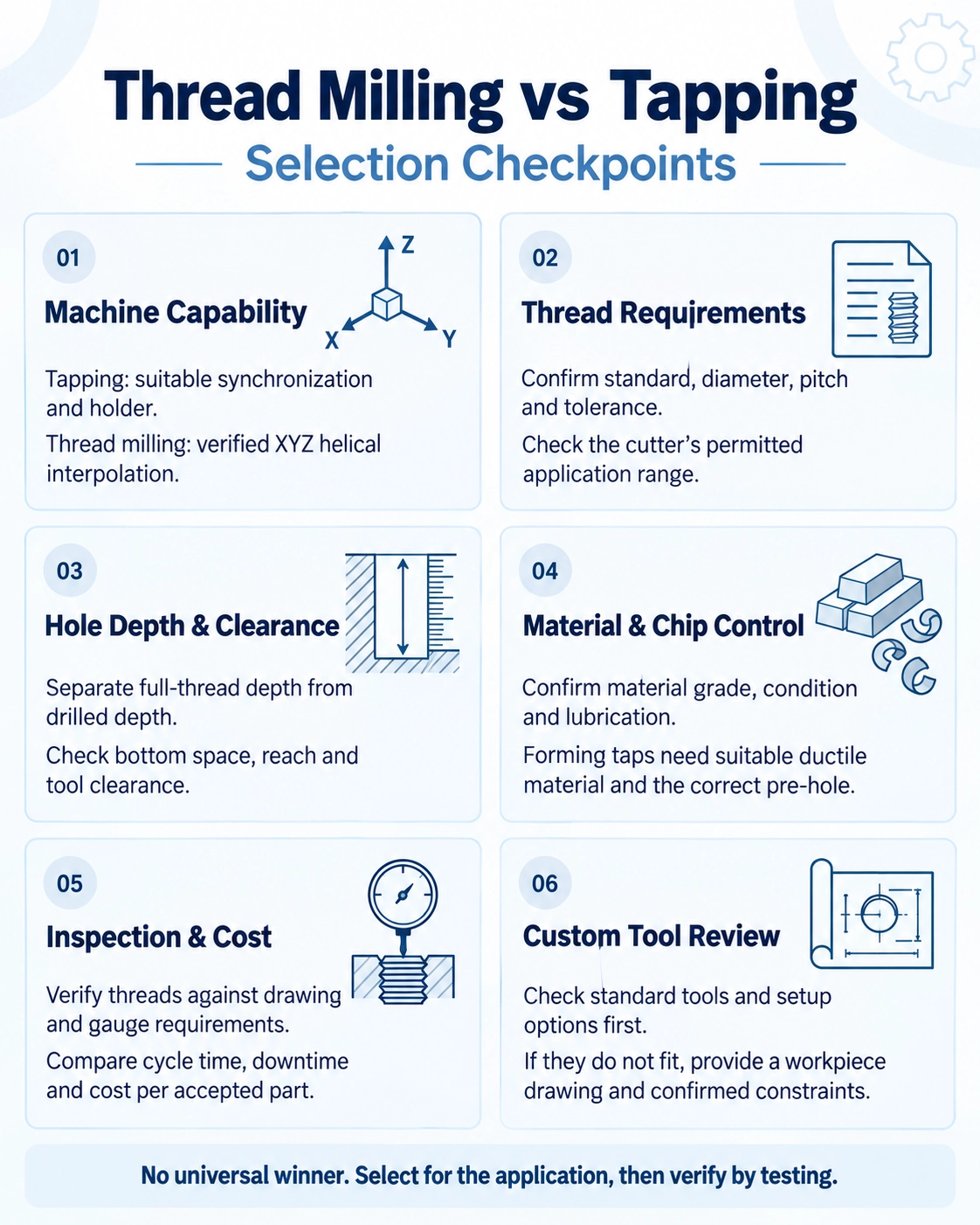
tool review when standard options do not fit.
Reviewing an incomplete customer inquiry
Consider a hypothetical message to a tooling reseller:
M10 × 1.5, stainless steel, blind hole, 100 pieces. Please quote.
The quantity is clear. The tool is not. First establish whether the customer wants the current product replaced or wants advice on a new process.
| Question | Why it matters |
|---|---|
| What is the current brand and complete model? | Establishes the comparison baseline |
| What thread tolerance is required? | Defines acceptance rather than nominal size alone |
| What are full-thread depth and drilled depth? | Reveals the actual bottom-clearance requirement |
| Which stainless grade and condition? | Narrows the application review |
| Which machine, holder and coolant arrangement? | Checks process feasibility |
| What must improve or remain unchanged? | Separates price sourcing from a machining problem |
Swipe to view all columns.
If the original tap is producing acceptable parts and the goal is a second supplier, begin with a comparable tap candidate. If the problem is size control or costly breakage, discuss whether thread milling is feasible before quoting it as a solution.
Limited information does not have to stop the conversation. A complete model code, catalog page or clear label photo can begin the review. List the unresolved details explicitly, and separate a preliminary product offer from an application-approved recommendation.
Frequently asked questions
Is thread milling better than tapping?
Not in every job. Choose against the customer’s machine, thread requirements, production volume and accepted process. A process change should earn its place through testing, not through a general claim of superiority.
Can one thread mill cover different thread sizes?
Possibly, within its published range. Check diameter, pitch, profile, reach and internal/external suitability. Do not extend one cutter family’s capability to all thread mills.
Can a forming tap replace a cutting tap directly?
Not without reviewing the process. Confirm material suitability, the forming tap’s pre-hole specification, lubrication and customer approval. Retaining the original cutting-tap drill size is not a safe assumption.
Are matching thread size and tool dimensions enough for replacement?
No. They support initial comparison, but geometry, tolerance, application range and sample results still matter. Specify a candidate replacement until acceptance has been established.
Do I need a tool drawing to request a custom thread mill?
A workpiece drawing can begin the discussion. Show the thread requirements, hole geometry and access limits. The proposed tool specification and manufacturing feasibility still need confirmation before production.
Need downloadable product specifications or starting cutting data? Visit our
แคตตาล็อกและไฟล์ดาวน์โหลด
for threading tool catalogs and technical guides.
Prepare a Replacement, Application or Custom Request
Existing-model replacement
Send the brand and full code, catalog page or clear label photos, quantity and replacement target. Identify what must remain unchanged.
New threading application
Send the thread standard, size, pitch and tolerance; material and condition; hole layout and depths; machine, holder and coolant details; and quantity.
Custom thread mill
Include the workpiece or tool drawing and explain what prevents a standard cutter from working. Mark access limits and full-thread depth, and state trial quantity and expected repeat demand. Dimensions, feasible scope and acceptance criteria need agreement before manufacture.