
Stainless Steel End Mill Chipping and Chatter: 6 Checks Before Replacing the Tool
Stainless steel end mill chipping at slot entry calls for a different investigation from regular chatter marks on a side wall. A chipped corner in 316 does not tell you whether a new cutter will solve the problem. Find the failure point before changing coatings, flute count or feed.
This guide covers six practical checks for common austenitic grades such as 304 and 316. It also helps resellers review an existing model even when their customer has not supplied a full process sheet. Other stainless families need their own application review.
How to Diagnose Stainless Steel End Mill Chipping and Chatter
If an edge is damaged or the cut becomes dangerously unstable, stop the cut. Then start with the symptom you can actually see:
Edge chips at entry
Look at the entry path, changing engagement and chips trapped near the edge.
Regular marks on the wall
Check projection, holder, runout and workholding before changing cutter geometry.
Material stuck to the edge
Inspect for built-up material before concluding that the coating has failed.
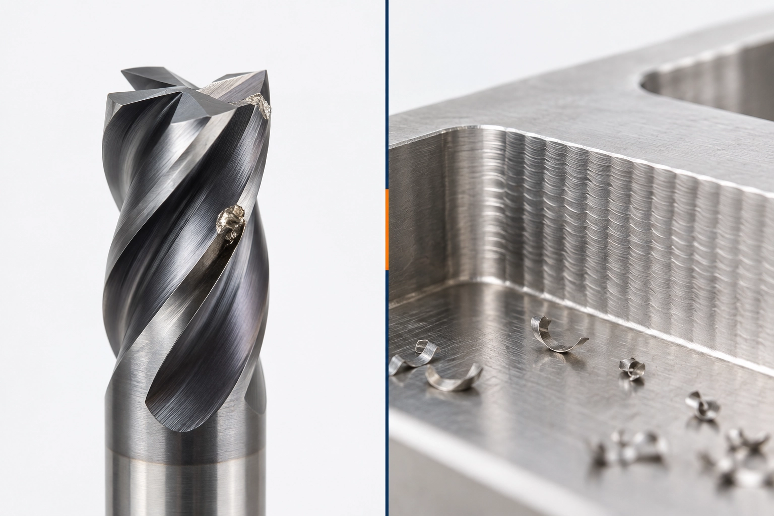
If wear grows gradually rather than appearing suddenly, record the wear pattern and cutting length. A tool and workpiece photo, together with the toolpath location, is more useful than a report of “poor tool life.” See Seco’s stainless-steel wear guidance.
Why Grade and Operation Change the Answer
Grades 304 and 316 are austenitic stainless steels. When an edge rubs instead of forming a stable chip, work hardening becomes a concern. Heat and chip behavior can also make a weak setup less forgiving. Yet “milling 316” does not tell us whether the cutter is side milling with light engagement or taking a full-width slot; the loads and available chip space differ.
Confirm the grade, material condition and operation first. The British Stainless Steel Association discusses work hardening and chip breaking. Sandvik Coromant separates austenitic stainless steels from ferritic, martensitic and duplex families in its milling guidance.
1. Locate the Failure in the Cut
Look first: What changed at the point where the tool began to chip or chatter?
A four-flute cutter may cut a straight side wall without trouble and fail when the program enters a slot or internal corner. In that case, the grade has not changed; engagement and chip flow have. Note the grade and condition, whether the cut is slotting or side milling, and where the damage begins: entry, steady cutting, corner or exit.
Also check whether the problem repeats on every tool and workpiece or occurs only with one setup. These observations narrow a replacement request more than asking for a “stronger” end mill.
2. Inspect the Used Edge and the Chips
Look first: Is the edge missing material, carrying a deposit or wearing gradually?
Photograph the whole cutter and damaged flute. Where safe, compare it with an unused edge under magnification. Built-up material can detach and sometimes take edge material with it; a phone photo alone may not settle whether you are seeing a deposit or chipped carbide.
Check whether chips are leaving the cut or being recut. Chip appearance alone cannot establish cutting temperature or identify a coating. Pair it with the edge condition and where the failure started.
Even a partial inquiry can start here: A reseller can request photos of the whole tool, cutting end and affected workpiece feature without asking the customer to reconstruct every machining parameter.
3. Examine the Assembled Setup
Look first: Can unnecessary projection be shortened, and is the cutter running true in its holder?
Regular wall marks or uneven wear between flutes justify checking stick-out, holder and collet condition, tool seating, workholding and spindle condition. If possible, measure runout near the cutting end. Catalog dimensions cannot describe runout after the tool is clamped; one flute may be doing more work than the others.
For deep features, record cutting depth, wall clearance and effective projection separately. Flute length, neck, shank and holder all affect access and rigidity. Variable pitch or helix geometry may help with chatter, but cannot secure a loose part or correct excessive runout. See Harvey Performance’s discussion of chatter and end mill geometry.
4. Review Chip Load at Entry and Corners
Look first: Did engagement or chip evacuation change immediately before the damage?
“Reduce the feed” is not a universal fix. An effective chip that is too thin may encourage rubbing, while excessive chip thickness raises edge load. Note slot entry, internal corners, abrupt exits and chips accumulating in the path. Seco explains how cutter entry, exit and chip thickness affect milling loads.
Technical detail: parameters and low radial engagement
For the specific cutter and operation, compare feed per tooth (fz), radial depth of cut (ae), axial depth of cut (ap), cutting speed and the actual toolpath. With low radial engagement, programmed fz and actual chip thickness are not the same. Use the exact tool maker’s guidance for a starting adjustment instead of changing table feed alone. Climb milling often suits a rigid CNC setup, but is not an unconditional rule for every machine or surface.
5. Match Flute Count and Geometry to the Operation
Look first: Is the tool doing a full-width slot, side milling, finishing or long-reach work?
“Four flutes or variable pitch?” is not a choice between equivalent features. Flute count affects the number of effective edges and available chip space. Variable pitch changes spacing between cutting edges; variable helix changes their helix pattern. One cutter can have four flutes and variable pitch.
| Operation | Review | Main trade-off |
|---|---|---|
| Full-width slotting | Edge support, chip space and chip removal | More flutes can leave less space per flute at a given diameter; verify the actual cutter design. |
| Side milling or profiling | Effective chip thickness and required reach | Weak clamping or excessive projection may outweigh a geometry change. |
| Chatter-sensitive finishing | Stable setup; variable pitch or helix where suitable | Geometry cannot correct excessive runout. |
| Deep feature | Flute length, neck clearance and projection | Reaching the part does not guarantee a stable cut. |
Swipe horizontally to compare all columns.
A stainless-oriented four-flute cutter may be a side-milling candidate, not a universal specification. Harvey Performance discusses flute count and chip evacuation. For product-range starting directions, see the HY Tools end mill series guide. Its HRC labels are product-series names; check the exact model before assuming stainless-steel suitability.
If the review points to changing the cutter, compare solid carbide end mills for stainless steel. Check the selected model’s dimensions and application range before requesting a sample or quotation.
See the end mill in the short product video below. For a stainless steel application, confirm the exact model’s dimensions and cutting geometry before arranging a sample trial.
6. Follow the Chips, Then Test the Candidate
Look first: Are chips clearing the feature, and does coolant or air reach the cutting zone consistently?
A slot or deep pocket can trap chips even when the flute openings look generous. Recutting them may damage an otherwise suitable edge. There is no useful “always dry” or “always wet” rule for every solid-carbide end mill; follow the exact tool maker’s guidance when preparing the trial.
Compare samples on the same material and feature, with the same holder and inspection method where practical. Agree beforehand how you will judge accuracy, finish, burrs, stability and wear after a defined cutting length or part count. Change one meaningful variable at a time.
Technical detail: what to record during the sample trial
Record the cutter model and size, projection, measured runout if available, vc or rpm, fz, ae, ap, coolant or air delivery and toolpath. Without these conditions, a better or worse result may be difficult to attribute to the replacement cutter.
How a Reseller Can Review an Existing Model
A customer asks: “Our Ø8 end mill chips in 316. Can you quote an alternative?” That is enough to start a review, but not enough to claim an equivalent replacement.
Illustrative process: This example explains the review steps; it is not a HY Tools test result.
Get the current reference
Ask for the maker and complete model code, catalog page or packaging label. Clear tool and cutting-end photos can start the review when the code is missing.
Separate facts from guesses
Check diameter, shank, flute count, cutting length, overall length, corner and neck. List unverified geometry or coating instead of inferring it from color.
Ask for the missing application facts
Confirm grade, slotting or side milling, failure point, required reach, coolant method and intended quantity.
Agree how to approve the sample
State what matches, what differs and which accuracy, finish, stability and wear results will determine approval.
Until critical specifications and the sample result are checked, call it a candidate for dimensional and application review. Ø8 and four flutes alone do not establish production equivalence.
Send What You Have; Fill the Gaps Together
Use the route closest to your situation. A completed process sheet helps, but it is not required for the first conversation.
New application
Start with: stainless grade, operation, feature size, approximate depth and quantity.
Before approval: confirm tolerance, reach, holder, coolant, strategy and test target.
Existing model
Start with: brand and full model, catalog page, drawing, label or clear photos; quantity.
Before approval: confirm critical dimensions, the operation, current failure and acceptance criteria.
Damaged tool
Start with: edge and part photos, material, tool size and the failure point.
For diagnosis: add current parameters, engagement, projection and holder or runout details if known.
Once the exact model has been chosen, use its manufacturer’s data and the carbide end mill speeds and feeds guide for starting calculations; general examples are not universal cutting values.
คำถามที่มักถูกถาม
Is a four-flute end mill always best for stainless steel?
No. Four flutes may suit some side cuts, but full slotting, light side milling, finishing and long-reach work make different demands on chip space, rigidity and edge loading.
Can variable pitch stop chatter without changing the setup?
It may help when vibration is related to the cutting pattern. Check overhang, holder runout, clamping and engagement first.
If the end mill chips, should I immediately lower the feed?
Not automatically. Find where the damage began and check for impact, increased engagement, rubbing, recut chips or built-up material. Too little effective chip thickness may make matters worse.
Can a reseller ask for a replacement with only a model or photo?
Yes. A full model code, catalog page or clear photos can begin an initial comparison. Application details and sample results are still needed before approval.
Before Changing the Tool
A new cutter may be part of the solution, but first establish what failed in this material, feature and setup. Otherwise, a new coating or flute pattern may enter the same unstable cut. End users can start with the application; resellers can start with the current model or customer photos.