HSS Spiral Flute Machine Taps – M2–M12, Fully Ground
Product Specifications
10 Pieces per Size
1–3 Days for In-Stock Sizes
Dimensions / Thread Tolerance / Coating / OEM
Consistent Quality
Consistent geometry across repeat orders.
Flexible Orders
Small batches and mixed sizes available.
OEM Support
Custom marking, labels and packaging.
Standard & Custom
Standard sizes and custom configurations.
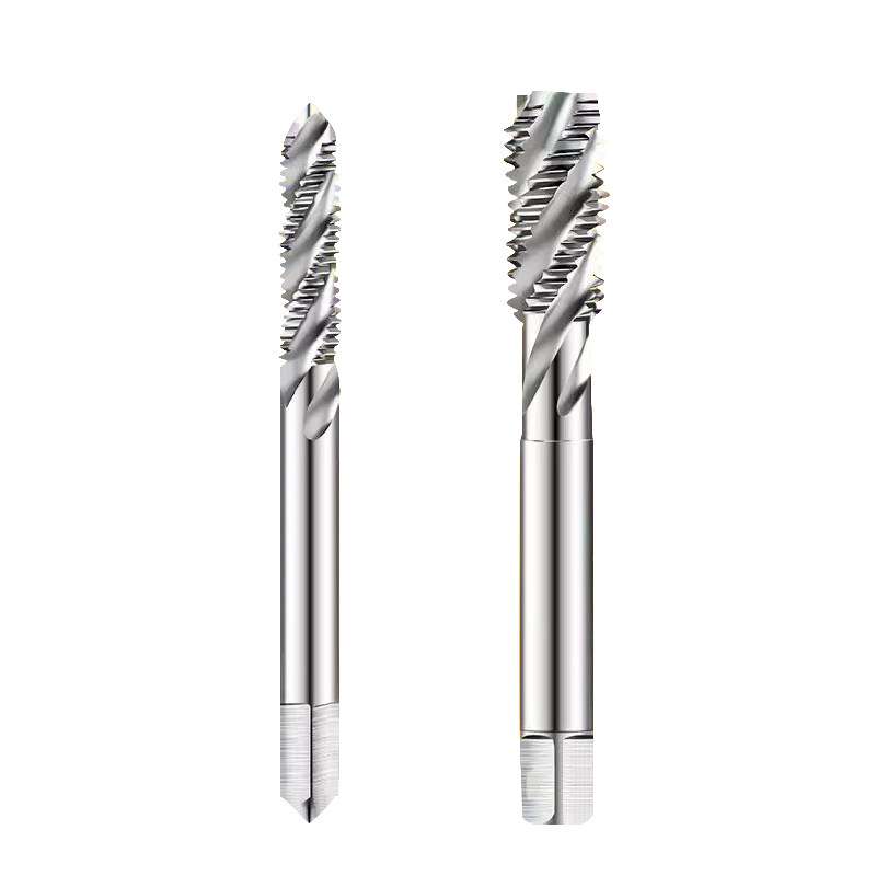
HSS Spiral Flute Machine Taps – M2–M12, Fully Ground
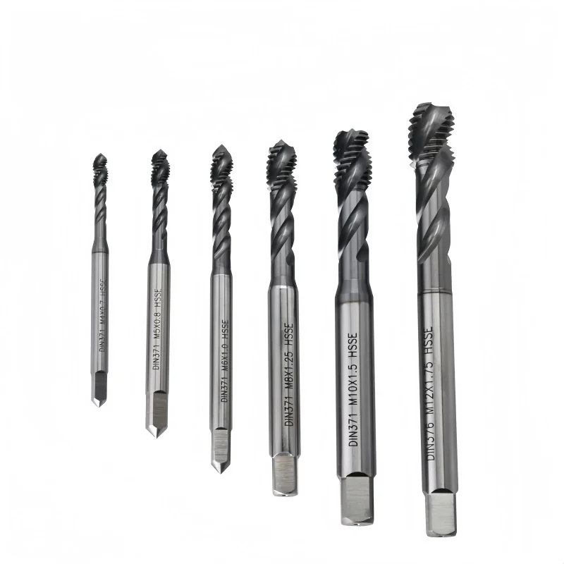
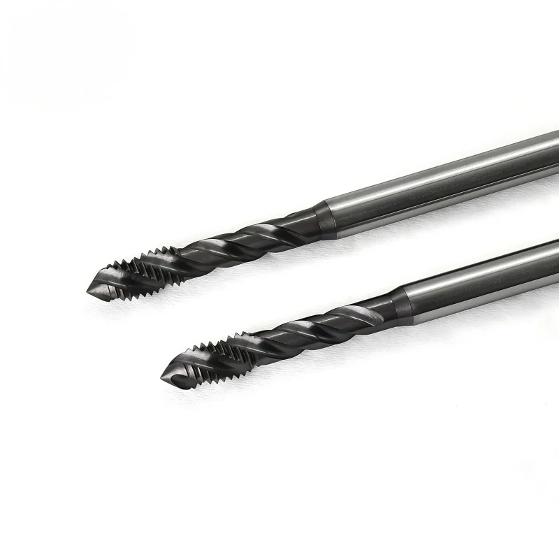
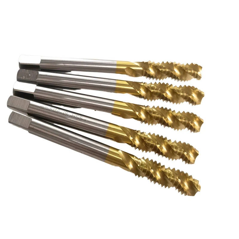
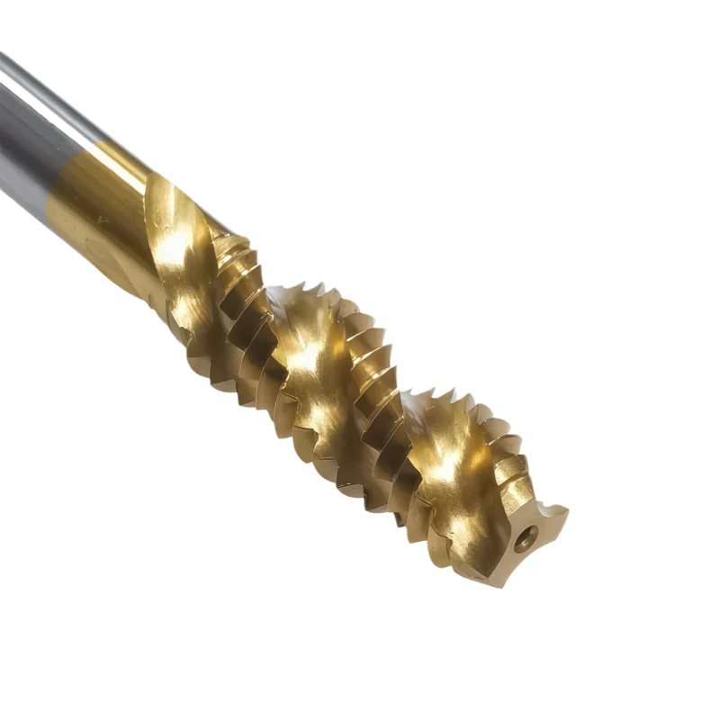
Fully ground HSS spiral flute machine taps for metric blind-hole threading from M2 × 0.4 to M12 × 1.75. The spiral flute geometry carries chips upward toward the shank during tapping, helping reduce chip accumulation at the bottom of the hole. The listed M2–M12 range uses a three-flute configuration with size-specific thread lengths, shank diameters and square-drive dimensions for machine tapping setup. Select the tap by complete thread size and pitch, required thread depth, holder fit and workpiece material, and confirm the lead geometry, thread tolerance and cutting conditions before production.
Key Configuration

Helical flute channels guide chips toward the shank, making this configuration particularly suitable for blind-hole tapping where chips cannot exit through the bottom.
Seven listed metric coarse sizes cover M2 × 0.4 through M12 × 1.75, with size-specific thread length, shank and square-drive dimensions.
Fully ground construction supports consistent flute, thread and shank geometry for repeatable machine-tapping setup without implying an unlisted thread tolerance class.
Key Product Advantages


Blind-Hole Chip Control
Spiral flutes direct chips away from the bottom of the hole during internal thread cutting.
Fully Ground Construction
Ground cutting features support controlled geometry and consistent tool dimensions across the listed range.
Three-Flute M2–M12 Range
All M2–M12 specifications shown in the supplied chart use a three-flute configuration.
Defined Shank & Square Drive
Shank diameter and square-drive dimensions are listed for holder compatibility checks before ordering.
Tapping Applications
This series is intended primarily for blind-hole metric threading on tapping machines, CNC machining centers and CNC lathes using a suitable holder and synchronized feed. Spiral flute geometry is particularly useful when chips need to be transported back out of the hole rather than pushed ahead of the tap.
Blind-hole tapping requires enough bottom clearance for the tap lead and chip accumulation. Confirm the pilot-hole diameter, required full-thread depth, material condition, lubrication and synchronized feed before production.
Workpiece Material Selection

Spiral flute taps are commonly evaluated for materials that produce continuous or longer chips, but the exact workpiece grade, hardness, lubrication and tap geometry must be confirmed before setting production parameters.
| MATERIAL GROUP | TYPICAL EXAMPLES | SELECTION NOTE |
|---|---|---|
| P Steel | Carbon and alloy steels | Confirm grade, hardness and lubrication |
| M Stainless Steel | Selected stainless steel grades | Application-specific geometry review required |
| N Non-Ferrous | Aluminum, copper and selected alloys | Confirm flute geometry and chip behavior |
The material groups above are selection references rather than a guaranteed compatibility list. The supplied data does not specify the exact HSS grade, coating, helix angle or material-specific tap geometry.
Selecting the Correct Spiral Flute Tap

Match the complete metric designation, such as M6 × 1.0 rather than nominal diameter alone.
Compare the required full-thread depth with the listed thread length and allow for chamfer and bottom clearance.
Check shank diameter, square thickness and square length against the selected tapping holder.
Confirm workpiece grade, hardness, pilot hole, lubricant and tapping speed before production.


For additional product options, browse our
HSS Tap Range.
For general selection guidance, see
How to Choose HSS Cutting Tools.
Size Chart & Specifications
The standard page range covers seven metric HSS spiral flute machine tap sizes from M2 × 0.4 to M12 × 1.75. Thread lengths range from 7 to 26 mm, shank diameters from 3 to 8.8 mm and overall lengths from 42 to 82 mm. All M2–M12 sizes shown use three flutes. Select the complete thread size and pitch first, then confirm thread depth, shank and square-drive dimensions against the tapping holder and machine setup.

The supplied dimensional image also contains M2 and M2.5 reference sizes. The standard product range presented on this page is M3–M12.
M3–M12 Main Dimensional Specifications
All dimensional values below are in millimeters unless otherwise stated.
| Size | Thread Length | Neck Length | Shank Dia. | Overall Length | Square Thickness | Square Length | Flutes |
|---|---|---|---|---|---|---|---|
| M3 × 0.5 | 9 | 14 | 4 | 46 | 3.2 | 6 | 3 |
| M4 × 0.7 | 11 | 17 | 5 | 52 | 4 | 7 | 3 |
| M5 × 0.8 | 13 | 22 | 5.5 | 60 | 4.5 | 7 | 3 |
| M6 × 1.0 | 15 | 26 | 6 | 63 | 4.5 | 7 | 3 |
| M8 × 1.25 | 19 | — | 6.2 | 70 | 5 | 8 | 3 |
| M10 × 1.5 | 23 | — | 7 | 75 | 5.5 | 8 | 3 |
| M12 × 1.75 | 26 | — | 8.8 | 82 | 6.5 | 9 | 3 |
Specification confirmation: HSS and fully ground construction are the stated product characteristics. The supplied data does not specify the exact HSS grade, thread tolerance class, chamfer form, spiral angle or coating. Confirm these items when they are critical to the application or purchasing specification.
How to Select the Correct Size
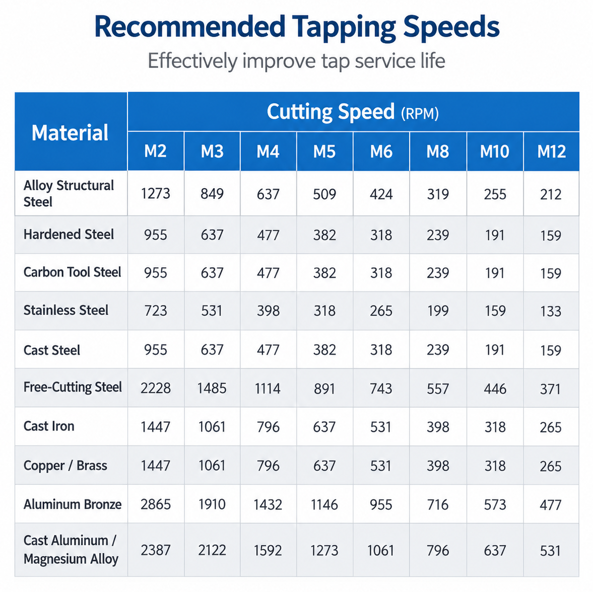
HSS Spiral Flute Tap Speeds & Feed Settings
Use the chart below as a general starting reference for M2–M12 HSS machine tapping. Confirm the workpiece grade and hardness, exact tap material, coating if applicable, thread depth, lubrication and machine condition before selecting the final spindle speed.
Setting Speed & Feed
Spindle speed: n = (1000 × Vc) / (π × D), where n is RPM, Vc is cutting speed in m/min and D is nominal tap diameter in mm.
Tapping feed: For single-start metric threads, feed per revolution equals thread pitch. When programming in mm/min, F = n × P, where P is thread pitch in mm.
Calculation example: An M6 × 1.0 tap running at 400 RPM requires a synchronized feed of 400 mm/min, or 1.0 mm/rev. This is a calculation example only and not a material-specific cutting-speed recommendation.
For additional reference, see our HSS cutting tools speeds & feeds guide.
For other machine-tapping configurations, browse our HSS Tap Range.
View HY Taps Catalog — for additional tap series and available configurations.
HSS Tap Customization
For requirements beyond the standard range, send your tap drawing or application details. Custom HSS cutting and forming taps can be reviewed for the following specifications.
| PARAMETER | CUSTOMIZATION OPTIONS |
|---|---|
| Thread Specification | Metric, UNC/UNF and pipe threads; special diameters, pitches and left-hand threads. |
| Thread Accuracy | Tap limits and oversize allowances to suit the required internal-thread tolerance and gauging requirements. |
| Tap Geometry | Straight flute, spiral flute, spiral point or forming design; chamfer and working geometry matched to the application. |
| Length & Reach | Overall length, threaded-section length and neck clearance to suit thread depth and component access. |
| Shank & Drive Square | Shank diameter, square dimensions and holding length to match the tapping holder. |
| Material & Surface Finish | HSS or cobalt HSS grades; uncoated, TiN or TiCN options, depending on the tap design and workpiece material. |
Options depend on tap type and size. Final specifications, minimum order quantity and lead time are confirmed with the quotation.
OEM & Private Label
Customer branding and packaging can be specified for distributor and tooling-brand orders.
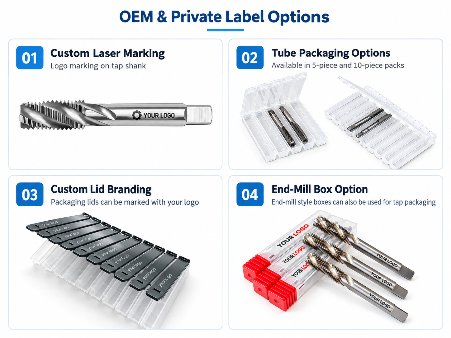
Laser marking: Logo, thread size, product code and batch identification, subject to available shank space. Labels & packaging: Protective tubes, product labels and branded packaging to the approved artwork.
For a quotation: Send a drawing or thread specification, required tolerance, workpiece material and hardness, blind or through-hole details, thread depth and quantity. Include machine, holder and lubrication details for application-specific requests.
HSS Tap Quality & Inspection
HSS cutting and forming taps are checked against the confirmed product specification or approved drawing. Material verification, in-process dimensional checks and final inspection focus on thread accuracy, tool geometry and consistent identification before packing.

Key Inspection Points
Inspection items and acceptance criteria depend on the tap type, size and agreed requirements.
| INSPECTION ITEM | CHECK POINTS |
|---|---|
| Material & Hardness | HSS or cobalt HSS grade and material records; hardness requirements and verification agreed for the selected grade. |
| Thread Form & Accuracy | Thread size, pitch, profile and specified tap limits against the confirmed specification or drawing. |
| Working Geometry | Flutes, spiral point and cutting edges for cutting taps; forming lobes and lubrication grooves, where present, for forming taps. Chamfer geometry checked for each design. |
| Tool Dimensions | Threaded-section length, overall length, shank diameter and drive-square dimensions. |
| Runout & Surface Condition | Specified runout, burrs, chipped edges and visible defects on cutting or forming surfaces. |
| Coating & Identification | Specified surface finish or coating, visible condition, tool marking and label accuracy. |
Inspection documentation: Specify any required material records, dimensional reports or sample-thread validation before ordering. Availability and inspection scope are confirmed with the quotation.
Packaging & Batch Identification
Individual protective packaging helps prevent damage to tap threads and working surfaces. Labels identify the tool specification and order or batch reference. Models, quantities and packing details are checked before dispatch.

Export Packing & Delivery
Outer cartons, cushioning and export packing are selected for the order quantity and shipping method. Dispatch dates, freight and payment terms are confirmed with the order.


FAQ & Technical Support
Selection, blind-hole preparation, machine setup and ordering guidance for M2–M12 fully ground HSS spiral flute machine taps.
Product & Application FAQs
Which sizes are available in this spiral flute tap series?
The standard product range on this page covers seven metric coarse-thread specifications: M2 × 0.4 M3 × 0.5, M4 × 0.7, M5 × 0.8, M6 × 1.0, M8 × 1.25, M10 × 1.5 and M12 × 1.75. Listed thread lengths range from 7 to 26 mm, shank diameters from 3 to 8.8 mm and overall lengths from 42 to 82 mm. All listed M2–M12 sizes use a three-flute configuration.
How does a spiral flute tap differ from straight flute and spiral point taps?
A spiral flute tap uses helical flute channels to carry chips back toward the shank and out of the hole, which makes it particularly useful for blind-hole threading. Straight flute taps use axial grooves and require application-specific chip control, while spiral point taps are generally selected when chips can be directed forward through the hole. Final selection should consider hole type, workpiece material, chip behavior and required thread depth.
Why are spiral flute taps commonly used for blind holes?
In a blind hole, chips cannot exit through the bottom. The spiral flute geometry helps transport cutting chips upward toward the shank, reducing chip accumulation near the bottom of the hole. The required hole depth must still provide enough clearance for the tap lead and remaining chips, so the listed thread length should not be treated as the guaranteed full-thread depth.
Which workpiece materials should I consider for this series?
Spiral flute taps are commonly evaluated for materials that produce continuous or longer chips, including many carbon and alloy steels, selected stainless steels and non-ferrous alloys. The exact material grade, hardness, tap geometry, lubrication and cutting conditions must still be confirmed. The supplied dimensional data does not establish universal suitability for every steel, stainless steel or non-ferrous alloy.
How should I determine the required thread depth and bottom clearance?
Start with the required full-thread depth on the part drawing, then compare it with the listed thread length of the selected tap. Additional hole depth is required for the tap lead or chamfer and for safe clearance at the bottom of the blind hole. There is no single fixed clearance value for every application; confirm the lead geometry, hole depth and chip space before production.
What does “fully ground” mean for this HSS machine tap?
Fully ground construction means the functional tap geometry is produced by grinding rather than relying only on formed or rolled tool surfaces. This supports controlled thread, flute and shank geometry for repeatable machine tapping. It does not by itself specify the HSS grade, thread tolerance class, coating, chamfer form or spiral angle, so these items should be confirmed when they are critical to the order.
Can these spiral flute taps also be used for through holes?
A spiral flute tap can be evaluated for some through-hole applications, but this series is positioned primarily for blind-hole tapping. Where chips can pass through the workpiece, another tap geometry may provide more suitable chip evacuation. Select the tap according to hole type, material, chip direction and production conditions rather than thread size alone.
What machine setup and tapping conditions are required?
Use a compatible tapping holder, correct tool alignment, a suitable pilot-hole diameter and appropriate lubrication. Feed per revolution must match the thread pitch during synchronized tapping. Spindle speed depends on tap diameter, workpiece grade and hardness, tool material, lubrication and machine condition. Validate the initial settings with a trial thread before batch production.
Ordering & Customization FAQs
What information is needed for a quotation?
Provide the complete thread size and pitch, quantity per size, workpiece material and hardness, blind-hole depth, required full-thread depth and finished-thread tolerance. Also include the pilot-hole specification, machine or holder requirements, coating or surface-treatment requirements and a drawing when standard dimensions do not fit the application.
Can non-standard dimensions and OEM branding be supplied?
Custom thread specifications, dimensions, flute or reach requirements, material grades, coatings, laser marking and packaging can be reviewed according to the requested application and order quantity. Critical dimensions, tolerance requirements and inspection criteria should be confirmed before production.
Are sample orders and mixed M2–M12 sizes available?
Sample and mixed-size requests can be reviewed for the listed M2–M12 range. MOQ, stock availability and lead time depend on the selected sizes, quantities and customization requirements. Send a size-and-quantity list together with the workpiece and application information for confirmation.
Selection Guides
Use the HSS guide for general tool-material selection, compare tapping with thread milling where appropriate, and browse the HSS tap range for alternative tapping configurations.
Catalog & Technical Downloads
HY Taps Catalog (PDF)General tap series reference. Use this product page’s Specifications & Sizes section for the current M3–M12 fully ground spiral flute tap dimensions; specifications in other catalog series may differ.
HSS Cutting Tools Speeds & Feeds Guide (PDF)General HSS drilling and tapping reference. Confirm the final tapping speed for the selected workpiece, tap size and tool configuration. For synchronized tapping, feed per revolution must match the thread pitch.
Need Sizes, Pricing or Custom Options?
Send us the required tool type, sizes, quantities, workpiece material and any OEM or custom requirements. We will confirm suitable specifications, availability, lead time and quotation details.
Drawings, size lists and reference photos are welcome.