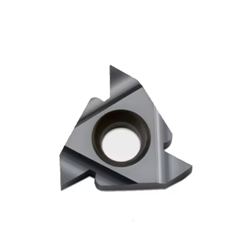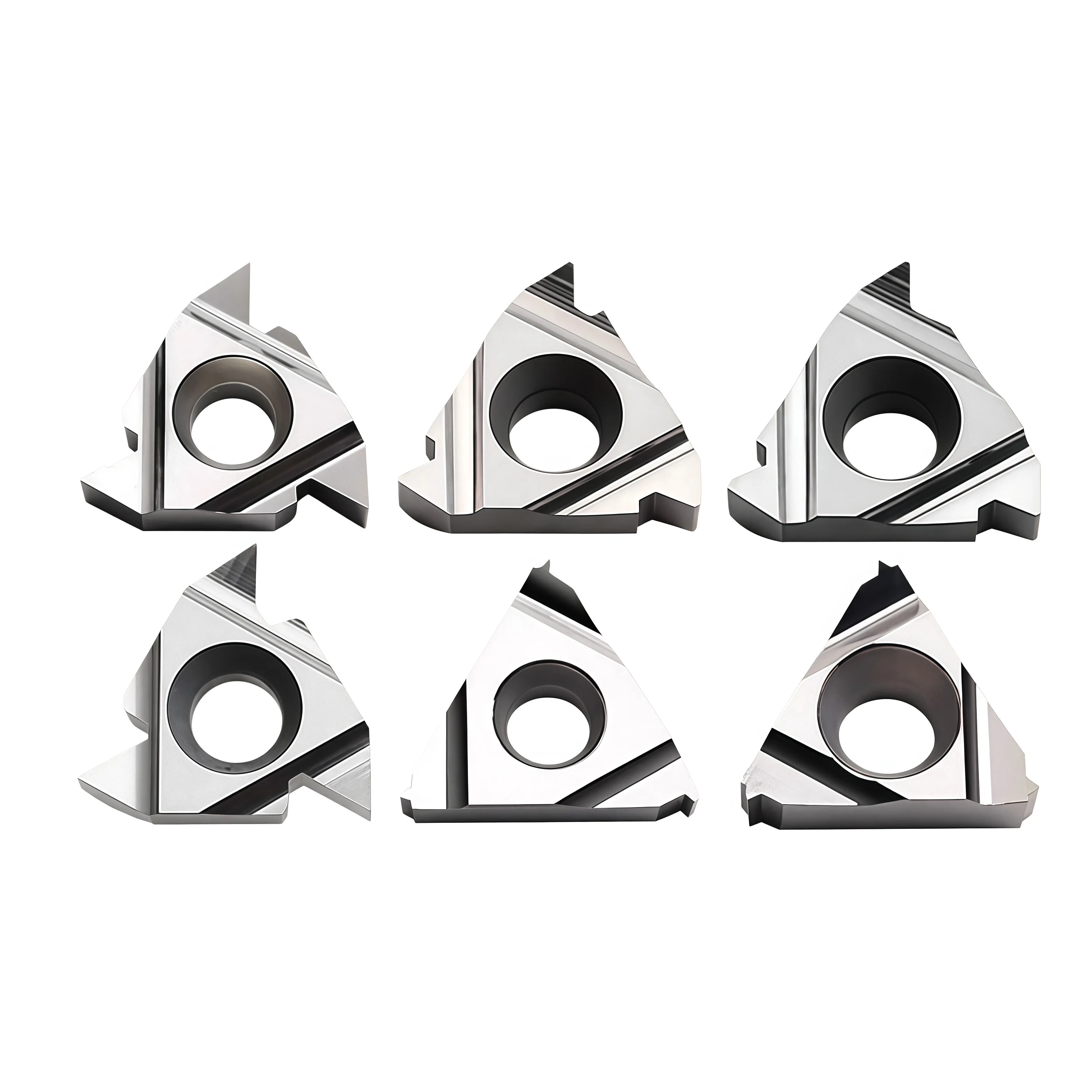

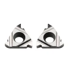
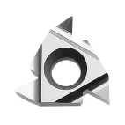
55°/60° ER/IR Carbide Threading Inserts for Aluminum
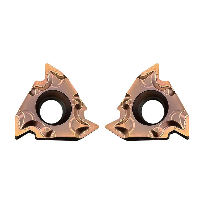
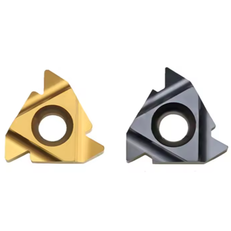
The 55° and 60° ER/IR carbide threading insert range is designed for external and internal threading of aluminum and other non-ferrous materials. Sharp cutting geometry and polished chip-control surfaces help reduce material adhesion, cutting resistance and burr formation, supporting clean thread profiles and consistent results across repeat machining batches.
Consistent Quality
Consistent geometry across repeat orders.
Flexible Orders
Small batches and mixed sizes available.
OEM Support
Custom marking, labels and packaging.
Standard & Custom
Standard sizes and custom configurations.
◆55°/60° ER/IR Carbide Threading Inserts Overview
This carbide thread-turning insert range for aluminum covers separately selected 55° and 60° thread profiles for external and internal CNC lathe operations. ER denotes an external insert; IR denotes an internal insert. Sharp edges and, where specified, polished chip faces help limit built-up edge and support clean thread flanks in aluminum and selected non-ferrous alloys.
Choose the exact insert by thread standard, profile angle, pitch or TPI, insert size and holder. The 60° group can address specified metric or Unified thread forms; the 55° group is associated with Whitworth-form threads. Full-profile and partial-profile versions require different crest preparation and inspection. Confirm the ordered geometry, substrate, surface finish and coolant conditions before production.
◆Key Configurations
| Configuration | Selection Point |
|---|---|
| ER / IR | External / internal thread turning; use the corresponding holder. |
| 55° / 60° | Separate cutting profiles selected to match the specified thread standard. |
| Insert size | 11 and 16 family references appear in the existing description; confirm exact codes and dimensions by item. |
| Finish / coating | Sharp, polished uncoated or application-specific coated options only where confirmed for the complete code. |
◆Cutting Features
Sharp aluminum geometry: a suitable edge and rake-face finish help shear ductile material with lower adhesion when the selected configuration supports them.
External and internal options: select ER or IR according to the thread location, available clearance and compatible toolholder.
Profile selection: 55° and 60° require separate insert geometries; a single edge cannot produce both profile angles.
Controlled setup: thread quality depends on pitch-matched feed, suitable infeed passes, boring-bar rigidity, chip clearance and final gauging.
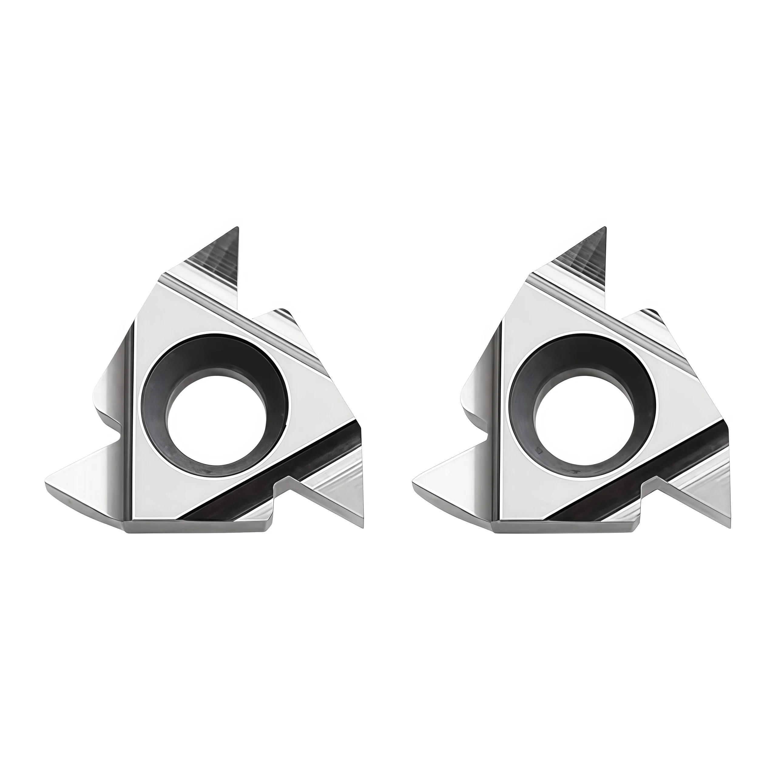
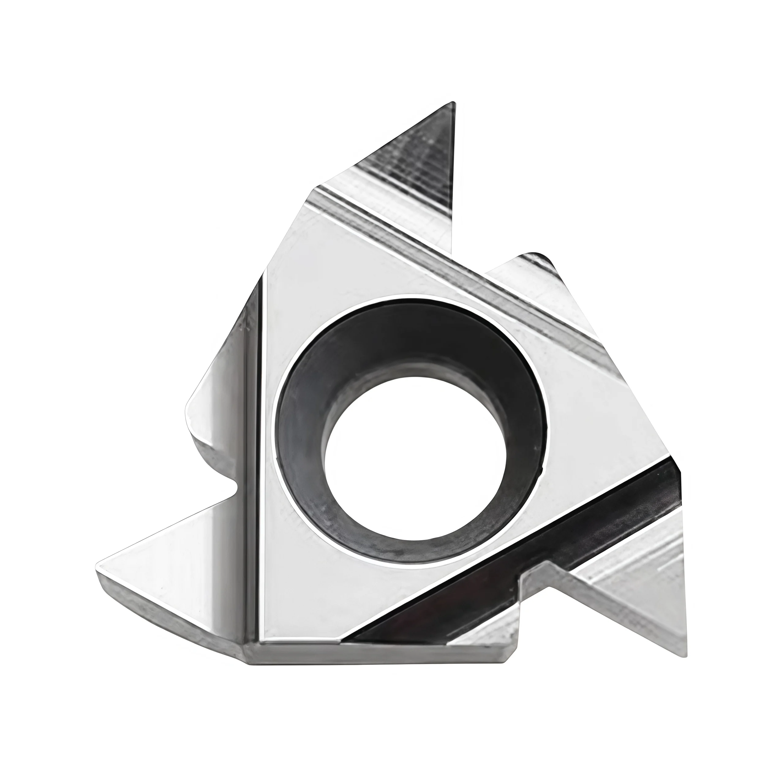
◆Original Product Images



◆Application & Ordering
Primarily specify these inserts for aluminum and selected non-ferrous alloys after confirming the exact edge and grade. For a quotation, send the thread standard, pitch or TPI, external/internal location, hand, full insert and holder codes, workpiece alloy, quantity and required packaging.
See our CNC Insert Selection Guide or request a specification check.
◆Specifications & Configurations
This page covers a family of aluminum-oriented carbide threading inserts. Select external or internal use, 55° or 60° form, and the pitch-specific or partial-profile edge as separate specifications. The existing detail page does not provide a verified dimension chart or complete SKU list for every combination.
| Parameter | What to Specify |
|---|---|
| Insert family | ER for external threads; IR for internal threads. The description mentions 16ER, 16IR and smaller 11IR references; confirm each complete model. |
| Thread form angle | 55° or 60° as distinct cutting profiles, selected by the drawing. |
| Thread standard | State the exact metric, Unified or Whitworth-related standard; 55°/60° alone does not establish crest, root, taper or tolerance. |
| Pitch / profile | Provide pitch in mm or TPI and identify full profile or partial V-profile; confirm the complete insert designation. |
| Material focus | Aluminum alloys and other approved ISO N materials; verify the exact alloy and silicon content. |
| Edge / finish | Sharp or polished aluminum geometry where available for the requested SKU; uncoated or coating option by confirmation. |
| Holder fit | Match insert size, seat, clamp, hand, shim and holder maker's approved designation; confirm minimum bore for IR. |
| Packaging | Box quantity, mixed codes and OEM label options confirmed by quotation. |
◆Profile Selection
| Selection | Practical Meaning |
|---|---|
| 60° | Use an insert designed for the specified 60° standard, such as metric or Unified, with the correct pitch and crest/root requirements. |
| 55° | Use a separately ground 55° insert for the specified Whitworth-form thread; check BSW, BSF or BSP details individually. |
| Full profile | Pitch-specific form can cut the crest when sufficient stock is provided; match its standard and exact pitch. |
| Partial V-profile | May cover a stated pitch range but does not top the crest. Prepare the major or minor diameter correctly and inspect the finished thread. |
◆Cutting Data & Confirmation
For a single-start thread, axial feed per revolution follows the specified pitch: feed = pitch in mm/rev, or 25.4 ÷ TPI in mm/rev. Program the threading cycle with multiple controlled infeed passes; “full depth” is not a one-pass instruction.
Choose cutting speed and pass schedule from the confirmed insert grade, aluminum alloy, thread size, external/internal setup, holder rigidity and coolant. The previous page's 200–1000+ m/min ranges, finish claims and percentage improvements are not validated for these SKUs and are omitted.
Send the thread drawing, complete insert and holder codes, material, bore or outside diameter, depth and quantity through our contact form for a model-specific dimension sheet and starting cutting data.
◆Carbide Insert Customization & OEM
Specify the insert around the machining operation, workpiece and holder. We can review standard replacements, application-specific geometry and private-label requirements using your insert designation, drawing or sample. Available grades, coatings, dimensions and order quantities are confirmed for each requested series.
Geometry & Chip Control
Review chipbreaker, rake, cutting-edge preparation, nose radius and corner design for the operation and workpiece. Confirm holder compatibility before approving a modified geometry.
Substrate & Coating
Select an available carbide grade and coating for the workpiece material, cutting conditions and desired balance of wear resistance and edge toughness.
Dimensions & OEM
Review insert size, thickness, locating and clamping features, tolerances, laser marking and private-label packaging against the approved specification.
◆Customization Options
Use the fields below when sending an inquiry. The exact options depend on the insert family and are confirmed in the quotation or approved drawing.
| Specification | Details to Confirm |
|---|---|
| Insert Type | Turning, milling, threading, grooving or drilling insert; send the designation or drawing. |
| Size & Fit | Shape, size, thickness, inscribed circle or edge length, hole or clamping form, and holder model. |
| Cutting Geometry | Chipbreaker, nose or corner radius, edge preparation, cutting direction and application-specific profile. |
| Grade & Coating | Workpiece group and grade, carbide substrate, coating system and wet or dry cutting conditions. |
| Tolerance & Inspection | Critical dimensions, profile requirements, inspection method and any required report. |
| OEM Presentation | Insert or box marking, label content, packaging format and quantity per pack. |
◆How to Request a Custom Insert

Send your insert requirements through our contact form or review our OEM and private-label service.
◆Carbide Insert Quality Control

Insert quality depends on the approved grade, geometry, coating and dimensional specification. We review the requirements at order confirmation and align the inspection scope with the insert series and any customer drawing. Share critical dimensions or documentation needs before production so they can be included in the agreed inspection plan.
01 · Incoming Material
Confirm the specified carbide grade or material documentation against the order requirements.
02 · In-Process Checks
Review dimensions and cutting-edge features during production against the approved specification.
03 · Final Inspection
Check the agreed dimensions, appearance, edge condition, coating identification and marking as applicable.
04 · Packing Review
Verify the item code, quantity, labels and protective packing against the approved order.
◆Inspection & Documentation
Inspection points and acceptance criteria should be agreed for the ordered series. For custom inserts, the approved drawing takes priority over a generic catalogue description.
| Check Area | What to Confirm |
|---|---|
| Dimensions & Fit | Insert size, thickness, corner radius, clamping features and any drawing tolerances. |
| Cutting Geometry | Chipbreaker, edge preparation, usable corners and profile where applicable. |
| Grade & Coating | Approved grade and coating designation; any requested verification method. |
| Appearance & Packing | Visible edge damage, marking, item code, count and packing format. |
| Requested Records | Inspection report, material or coating documentation, sample approval or batch identification when agreed. |
◆Order & Delivery
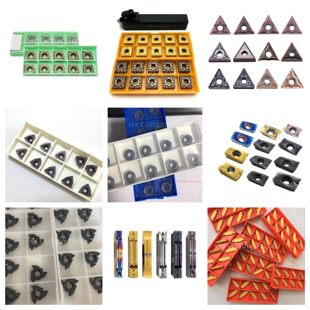

Share a line-by-line list of insert codes and quantities for a mixed-size quotation. Stock status, minimum quantity, sample requirements and production lead time are confirmed for each grade, coating and configuration.
Send your item list and quality requirements through our contact form for specification, availability and delivery confirmation.
◆Product FAQs
Can one insert cut both 55° and 60° threads?
No. These are separate cutting-edge profiles. Select 55° or 60° according to the thread drawing and order the corresponding complete insert code.
What do ER and IR mean?
ER denotes external thread turning and IR internal thread turning. Match the insert size, hand, seat and clamp to the appropriate external or internal holder; minimum bore and reach also matter for IR.
Which thread standards use the two angles?
Metric and Unified threads generally use 60° forms. Whitworth-related forms use 55°. Each standard also specifies pitch, crest/root geometry and tolerances. Do not identify a standard from its angle alone; UNJ is a 60° form, not a 55° option.
Should I choose a full-profile or partial-profile insert?
A full-profile insert is made for a particular pitch and can finish the crest. A partial V-profile can cover a specified pitch range but does not top the crest. Select by the complete thread specification and prepare the starting diameter accordingly.
What edge finish is useful for aluminum?
A sharp edge and suitable polished or low-adhesion rake face can help limit built-up edge in ductile alloys. Confirm whether the requested code is uncoated or has a specified coating; the product title does not establish one finish for every variant.
Is “full pitch, full depth” a usable feed and cut setting?
No. In single-start thread turning, axial feed per revolution follows the thread pitch, while thread depth is reached over multiple controlled passes. Select speed and the infeed schedule from the actual grade, alloy, thread and setup.
◆Ordering & OEM FAQs
Will an 11IR insert fit a 16IR holder?
Do not assume so. The size families and holder seats differ. Send the complete insert and holder models for a clamping and clearance check.
Are uncoated or DLC-coated versions available?
The product summary mentions these as options. Availability and suitability depend on the complete insert code and aluminum alloy; confirm substrate, edge preparation, coating and quantity before ordering.
Can I combine different profiles or request OEM packaging?
Send a line-by-line list with each full code, grade and quantity, plus the requested marking and label artwork. Mixed-model supply, MOQ, pack quantity and lead time are confirmed for the order.
What should I send for a quotation or replacement?
Provide the thread standard and size, pitch/TPI, 55° or 60° angle, full or partial profile, external/internal location, insert and holder codes, alloy, bore or outside diameter, threading depth, existing box-label photos and quantity.
◆Guides & Technical References
Use our CNC Insert Selection Guide for insert, grade and holder checks.
For an exact model drawing or quotation, send the thread drawing and complete insert code.
Need Sizes, Pricing or Custom Options?
Send us the required tool type, sizes, quantities, workpiece material and any OEM or custom requirements. We will confirm suitable specifications, availability, lead time and quotation details.
Drawings, size lists and reference photos are welcome.