


8D Through-Coolant Solid Carbide Drill for Precision Deep Hole Drilling
8×D Deep-Hole
Qualità costante
Consistent geometry across repeat orders.
Ordini flessibili
Small batches and mixed sizes available.
OEM Support
Custom marking, labels and packaging.
Standard e personalizzati
Standard sizes and custom configurations.
8D Through-Coolant Carbide Drill
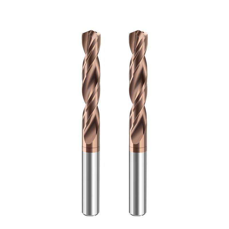
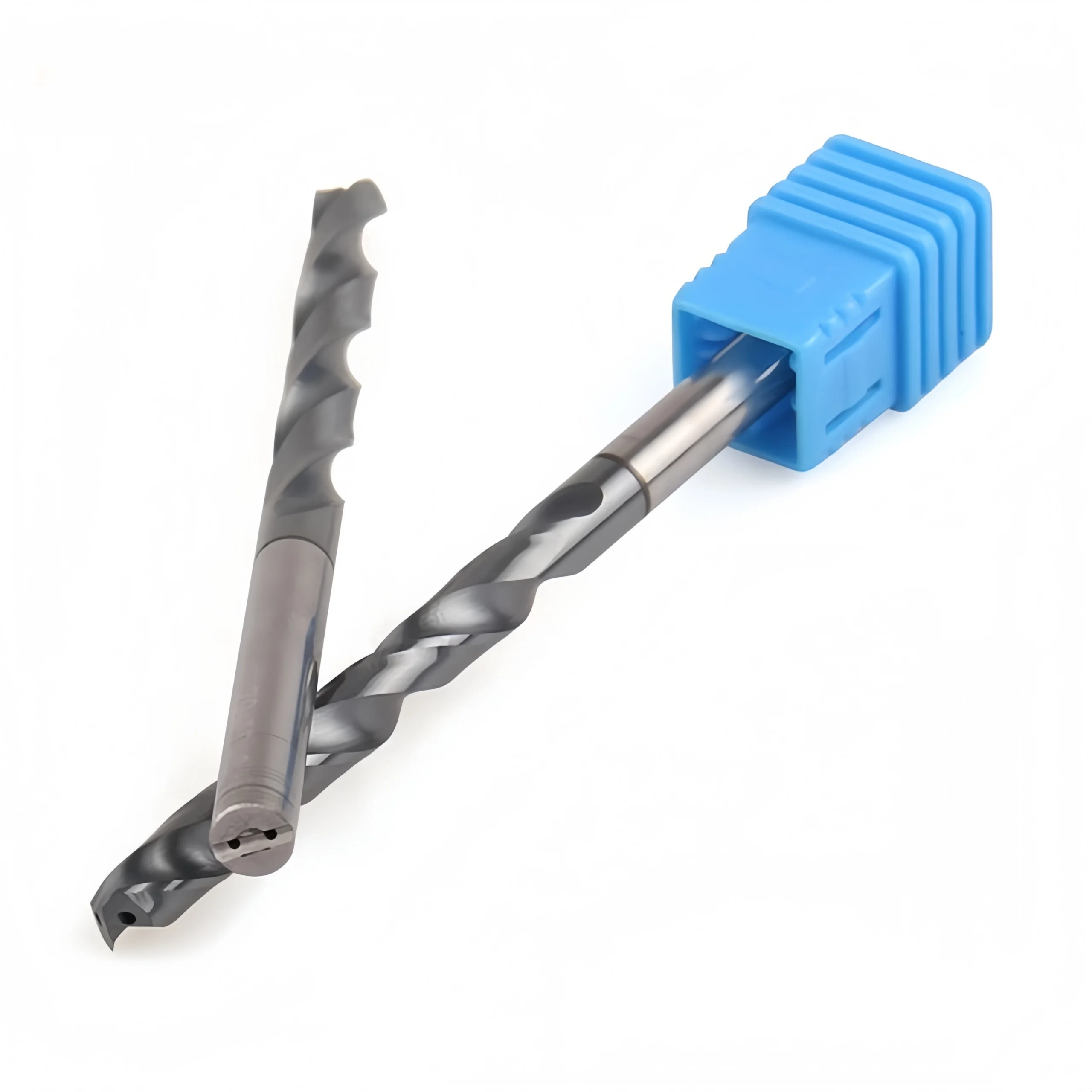
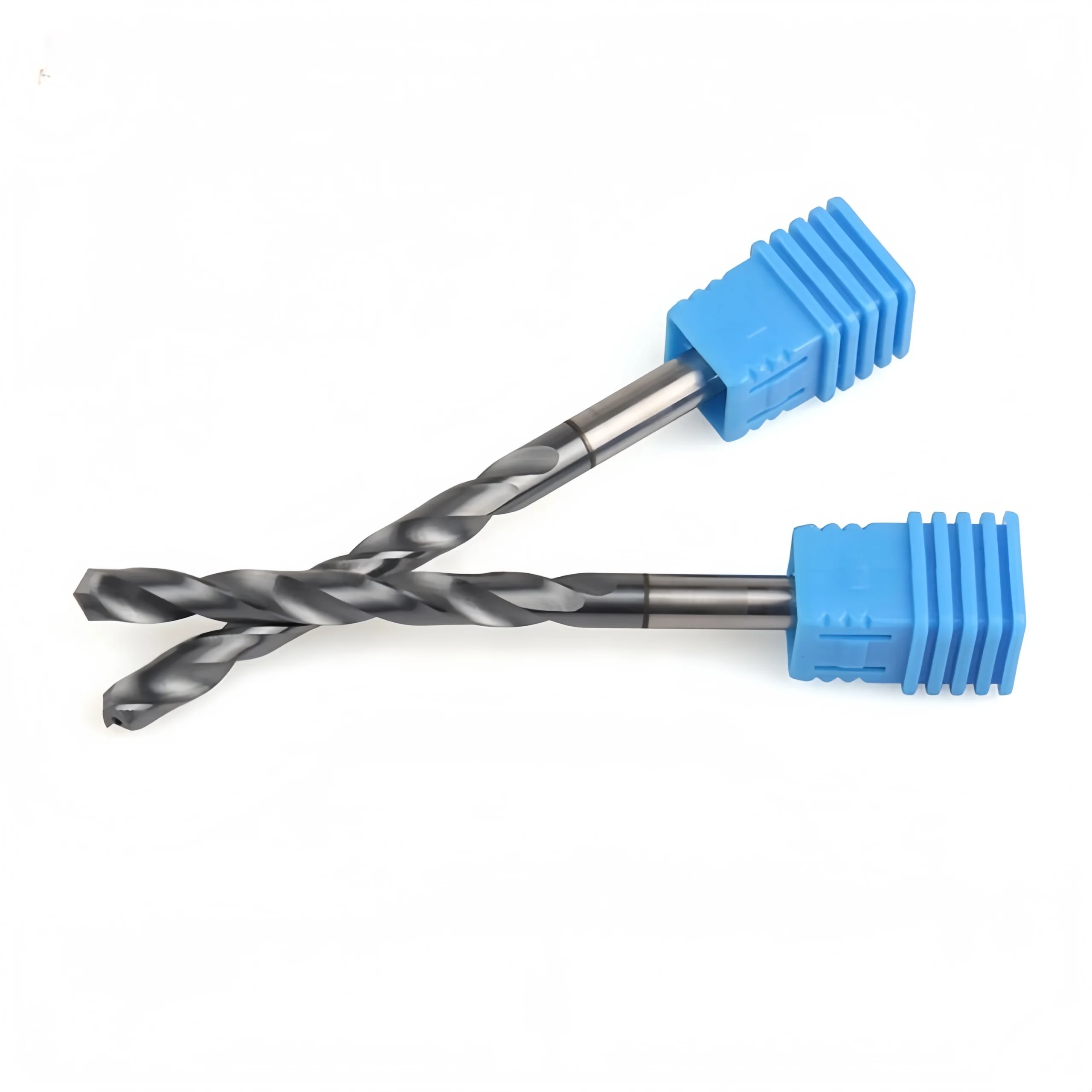
This 8D through-coolant solid carbide drill is designed for precision CNC hole machining to a nominal depth of eight times the cutting diameter. Internal coolant passages deliver cutting fluid directly to the drill point, helping control heat and move chips through the extended helical flutes. Its rigid carbide body, coated cutting section and straight-shank configuration support stable deep-hole drilling when coolant pressure, holder runout, workpiece clamping and cutting parameters are properly controlled. Standard cutting diameters range from Ø3 to Ø20 mm, with custom configurations available for application-specific requirements.
8×D
Through-Coolant
Carburo solido
Ø3–Ø20 mm
Key Configuration
1
8×D Deep-Hole Configuration
The extended cutting and flute section supports a nominal drilling depth of eight times the cutting diameter.
2
Internal Coolant Channels
Through-tool passages deliver coolant near the cutting edges to support cooling, lubrication and chip evacuation at depth.
3
Coated Helical Flute Design
Coated cutting edges and continuous helical flutes help manage wear and guide chips toward the hole entrance.
8D Through-Coolant Drill Configuration
Key Product Advantages
01
8×D Deep-Hole Capability
The extended flute section provides chip space for precision holes reaching a nominal depth of eight times diameter.
02
Targeted Coolant Delivery
Internal passages deliver coolant close to the drill point, where external coolant has limited access.
03
Rigid Carbide Construction
The solid-carbide body supports stiffness and dimensional stability during precision CNC deep-hole drilling.
04
Helical Chip Evacuation
Continuous flutes work with coolant flow to guide chips toward the hole entrance and reduce chip packing.
05
Coated Cutting Section
Application-matched coating options help protect the cutting edges against heat and abrasive wear.
06
Precision Straight Shank
The straight shank provides a consistent clamping surface for compatible low-runout precision holders.
Coolant Delivery at the Cutting Zone
Chip Flow: Coolant flow supports chip movement into and through the extended helical flutes.
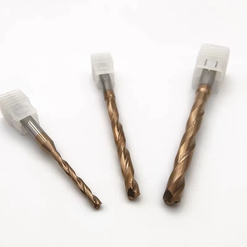
Product Geometry & Additional Views
Why Through-Coolant Matters at 8×D
At eight times diameter, the drill point is farther from external coolant and chips must travel a longer path out of the hole. Internal coolant delivery helps stabilize the cutting zone and supports more consistent chip evacuation.
Coolant reaches the drill point inside the hole.
Coolant flow assists chips along the extended flutes.
Stable cooling helps reduce thermal overload.
Consistent delivery supports repeatable CNC drilling.
Applications & Target Scope
- Mold cooling channels in mold plates and tooling components
- Deep passages in hydraulic manifolds, valve bodies and blocks
- Production drilling of automotive housings and structural components
- Repeatable 8×D holes in precision CNC machine parts
- Blind-hole and through-hole applications with controlled chip evacuation
- Application-specific deep-hole drilling with standard or custom geometry
Machining Requirements
• Minimize Runout
Use a clean, high-precision holder and keep the practical tool overhang as short as possible.
• Verify Coolant Supply
Confirm stable coolant pressure, adequate flow, suitable filtration and open coolant channels before drilling.
• Match Cutting Data
Select cutting speed and feed according to drill diameter, workpiece grade, hardness, coating and machine rigidity.
• Monitor Chip Evacuation
Stop and correct the process if chips pack in the flutes or coolant delivery becomes restricted.
Review the tooling system and CNC productivity guide for holder, runout, coolant and setup considerations.
Product Series Information
Technical configuration for 8D through-coolant solid carbide drills used in precision CNC deep-hole applications.
| Tipo di strumento | Through-Coolant Carbide Drill | Nominal Drilling Depth | 8×D |
| Materiale dell'utensile | Carburo solido | Diametro di taglio | Ø3–Ø20 mm |
| Flute Length Range | 30–190 mm | Overall Length Range | 70–244 mm |
| Shank Diameter Range | Ø6–Ø20 mm | Tipo di gambo | Gambo dritto |
| Coolant Supply | Internal / Through-Tool | Rivestimento | Selected by Application |
Tool Nomenclature & Dimensions
Reference dimensional symbols used in the standard 8D size matrix.
 d1: Diametro di taglio
L1: 8D Flute Length
L: Lunghezza complessiva
Depth: Nominal 8×D
d1: Diametro di taglio
L1: 8D Flute Length
L: Lunghezza complessiva
Depth: Nominal 8×DStandard 8D Size Matrix
Standard dimensional references retained from the original size chart. All dimensions are in millimeters.
| Cutting Diameter d1 | 8D Flute Length L1 | Overall Length L |
|---|---|---|
| 3 | 30 | 70 |
| 4 | 42 | 83 |
| 5 | 50 | 90 |
| 6 | 57 | 97 |
| 7 | 76 | 116 |
| 8 | 76 | 116 |
| 9 | 87 | 131 |
| 10 | 95 | 139 |
| 11 | 106 | 155 |
| 12 | 114 | 163 |
| 13 | 133 | 182 |
| 14 | 133 | 182 |
| 15 | 152 | 204 |
| 16 | 152 | 204 |
| 17 | 171 | 223 |
| 18 | 171 | 223 |
| 19 | 190 | 244 |
| 20 | 190 | 244 |
8D Through-Coolant Drilling Guidance
- Alimentazione del liquido di raffreddamento: Maintain stable through-spindle pressure, sufficient flow and suitable filtration.
- Channel Check: Confirm that both internal coolant passages are open before drilling.
- Rigid Setup: Use a clean low-runout holder and minimize unnecessary tool overhang.
- Chip Monitoring: Stop the cycle if chips begin packing in the flutes or coolant flow becomes restricted.
- Parameter Verification: Match speed and feed to the exact material grade, hardness, diameter and coating.
Recommended Starting Cutting Parameters
Use the technical guide as an initial reference and adjust the cutting data according to drill diameter, workpiece material, hardness, coolant pressure, hole tolerance and machine rigidity.
Solid Carbide Drill Cutting Data Guide
Access ISO-categorized starting speeds and feeds for deep-hole drilling trials.
Through-Coolant Drill Product Family
Compare related drill configurations according to the required depth-to-diameter ratio and production method.
3D Series
Short-Hole Drilling
5D Series
Medium-Depth Drilling
8D Series
Current Deep-Hole Option
Custom Coolant Drills
Drawing-Based Supply
For additional sizes and related drill series, View the Solid Carbide Drill Catalog.
Solid Carbide Drill Customization
Custom geometry, specialized coatings, and internal coolant options are engineered according to workpiece material specifications, ISO application groups, and specific hole tolerances.
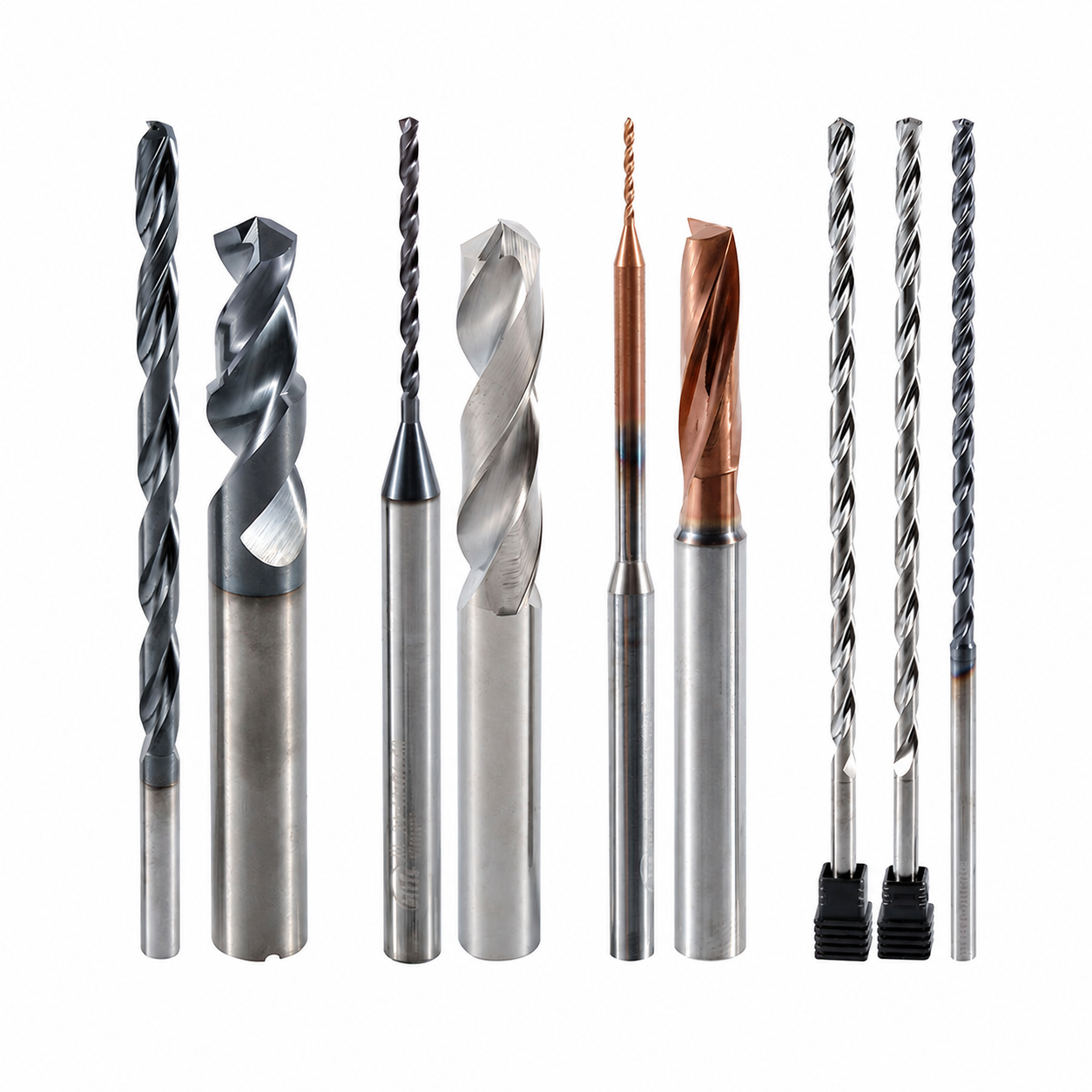
Custom Geometry & Edge Preparation
Precision-ground point angles, web thinning, edge honing, and flute profiles optimized for chip control in deep-hole operations.

Dimensions & Reach Options
Metric, fractional inch, and intermediate decimal diameters configured in standard (3×D, 5×D, 8×D) or extended-reach lengths.
Servizi OEM e a marchio privato
Turnkey OEM manufacturing options for industrial distributors, tooling brands, and high-volume machining facilities.
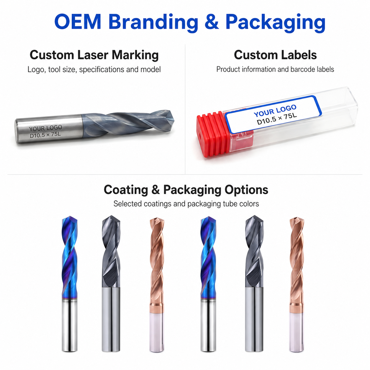
Laser Etching
High-precision laser marking for logos, tool codes, EDP numbers, and diameter designations.
Custom Packaging
Single plastic tubes, multi-pack boxes, specialized inserts, and custom color selections.
Commercial Terms
Flexible MOQ options tailored to custom specifications, standard trial runs, and scheduled supply contracts.
Technical Workflow
Inquiry
Submit drawing, material specification, and quantity.
Engineering
Application evaluation and drawing confirmation.
Commercial
Quotation approval, pricing, and lead-time confirmation.
Production
CNC grinding, edge preparation, and specialized coating.
Quality Control
Optical inspection, packaging, and dispatch.
Inspection & Quality Control
Drill dimensions, cutting-edge geometry and visible surface condition are checked according to the confirmed product specification and application requirements.

Protective Packing for Shipment
Finished drills are protected individually before batch labeling and export-carton reinforcement.

Individual Tool Protection
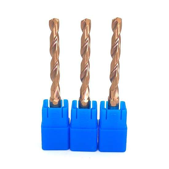
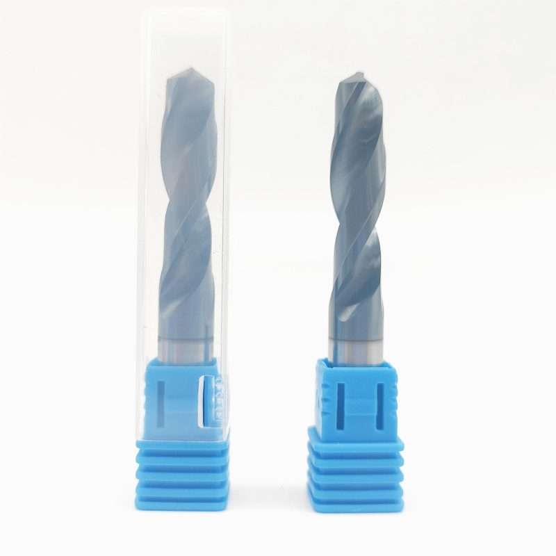
Each drill is individually protected in a plastic tube to reduce contact damage during storage, handling and transportation.
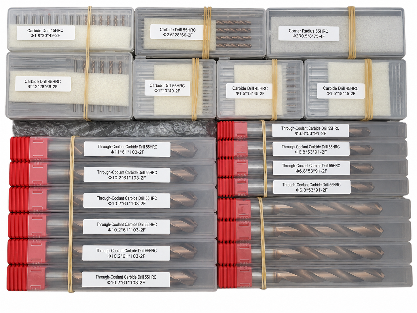
Batch & Label Verification
Tools are grouped and labeled by specification to support order verification before carton packing.

Export Carton Protection
Batch packaging, cushioning materials and reinforced export cartons are selected according to the order quantity and shipping method.
Reference Lead Time
The following timeframes are general references. Availability and production scheduling are reviewed for each order.
Shipping Options
Shipping arrangements can be selected according to order size, delivery schedule and destination.

Product FAQs
Product-specific information about applications, available configurations, customization and machining requirements for this carbide drill.
What materials and applications is this drill designed for?
This product is positioned for steel, stainless steel and selected non-ferrous materials. Final suitability should be confirmed from the exact workpiece grade, hole type, diameter, depth and machining conditions.
What is a 180° flat-bottom drill used for?
The 180° cutting geometry is suited to flat-bottom holes, counterboring and selected inclined-surface entries where a conventional drill point would not provide the required bottom profile.
What sizes and configurations are available?
Standard and custom sizes can be reviewed according to the product series. Diameter, flute length, overall length and shank dimensions should be confirmed before ordering.
What coolant method is suitable?
External coolant, air or mist can be selected according to the workpiece material, hole depth and machine setup. The final method should support stable chip evacuation and temperature control.
Can the coating be selected for the application?
Yes. The final coating should be confirmed according to the workpiece material, hardness, hole condition and expected cutting environment.
What information is required for a quotation?
Please provide the required diameter, hole depth or reach, workpiece material, coating requirement and estimated quantity. A drawing is recommended for custom or non-standard requirements.
Ordering & OEM FAQs
General information for trial orders, mixed-size purchasing, private labeling and production scheduling.
Do you accept small trial orders?
Yes. Small sample or trial orders are welcomed for testing and performance evaluation before committing to volume purchasing.
Can mixed sizes be ordered together?
Yes. Standard and custom sizes can be combined in one order when the production and coating requirements are compatible. Mixed-size purchasing is useful for distributors and batch inventory planning.
Is OEM laser marking available?
Yes. Custom shank laser marking such as logo, model number, specifications or batch identification can be reviewed together with OEM labels and packaging requirements.
What is the typical production lead time?
Standard stock items normally have a shorter lead time, while custom tools and special OEM orders require additional production time. The exact schedule is confirmed according to specification, quantity, coating and current production capacity.
Downloads & Technical Resources
Access product dimensions, series information and starting cutting data for product selection and application review.
Need Sizes, Pricing or Custom Options?
Send us the required tool type, sizes, quantities, workpiece material and any OEM or custom requirements. We will confirm suitable specifications, availability, lead time and quotation details.
Drawings, size lists and reference photos are welcome.