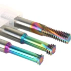
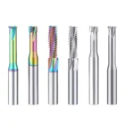
DLC-Coated Solid Carbide Thread Mill Series for Aluminum and Non-Ferrous Metals
DLC-COATED SOLID CARBIDE THREAD MILL SERIES
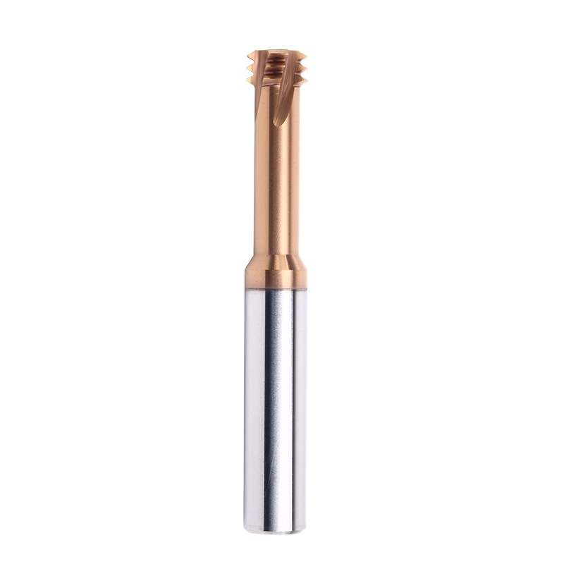
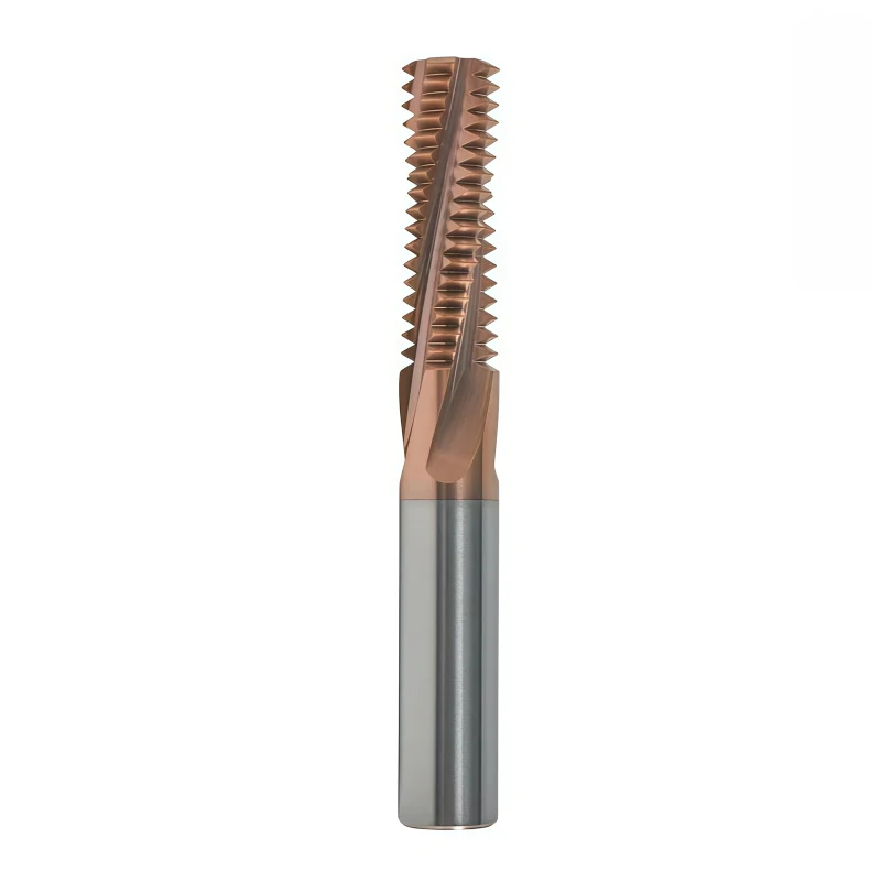
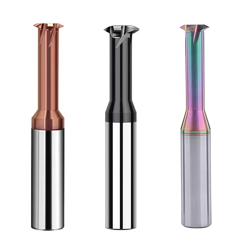
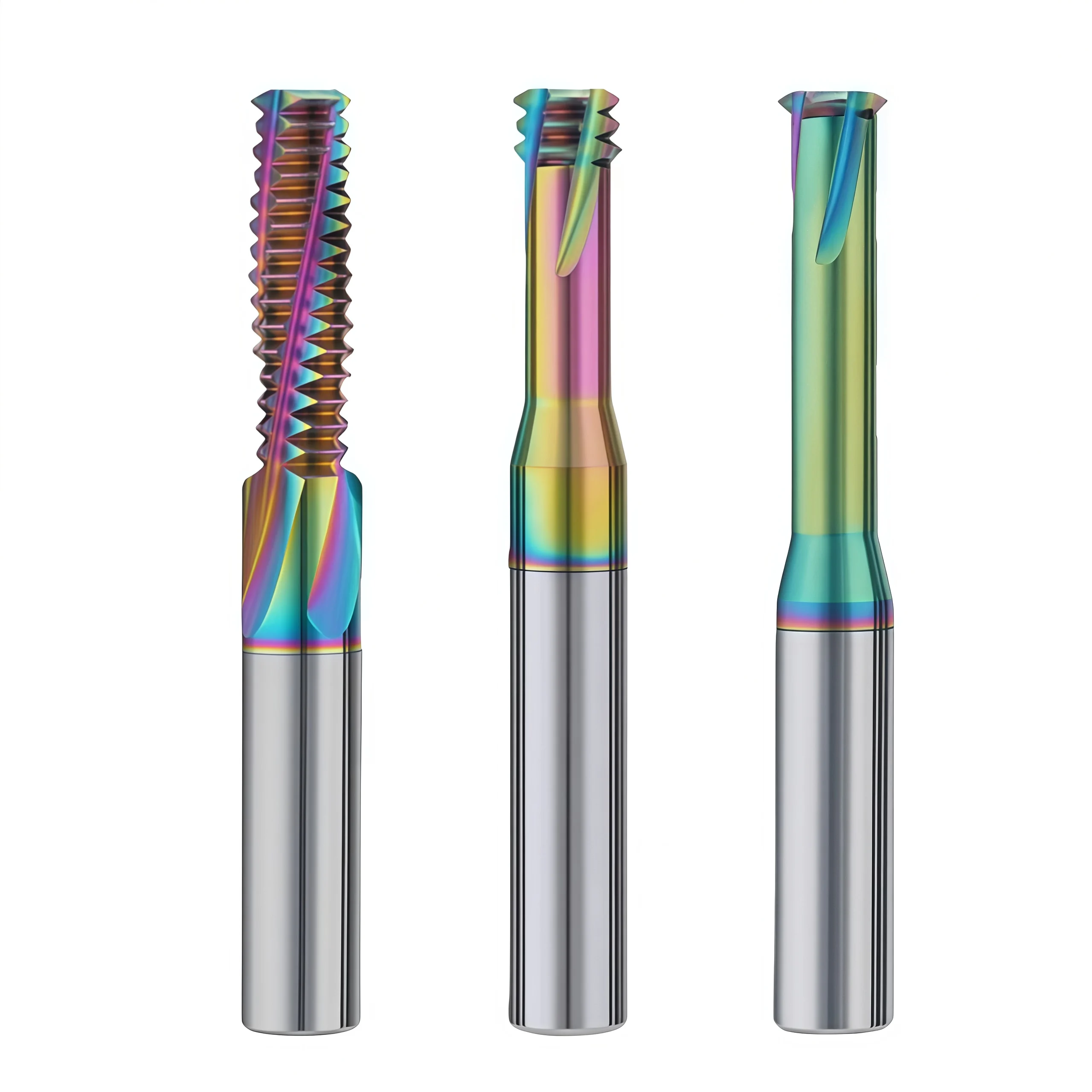
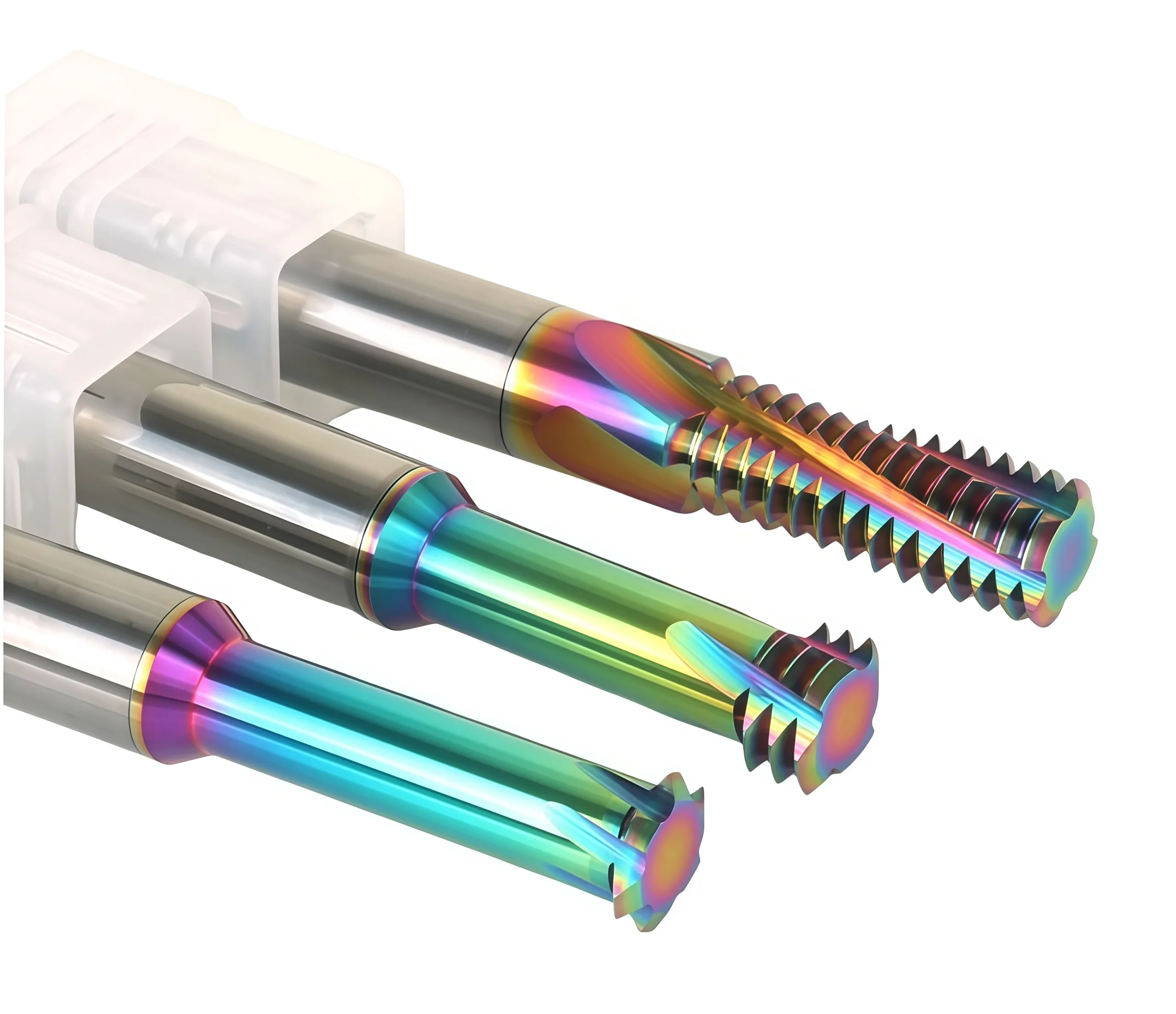
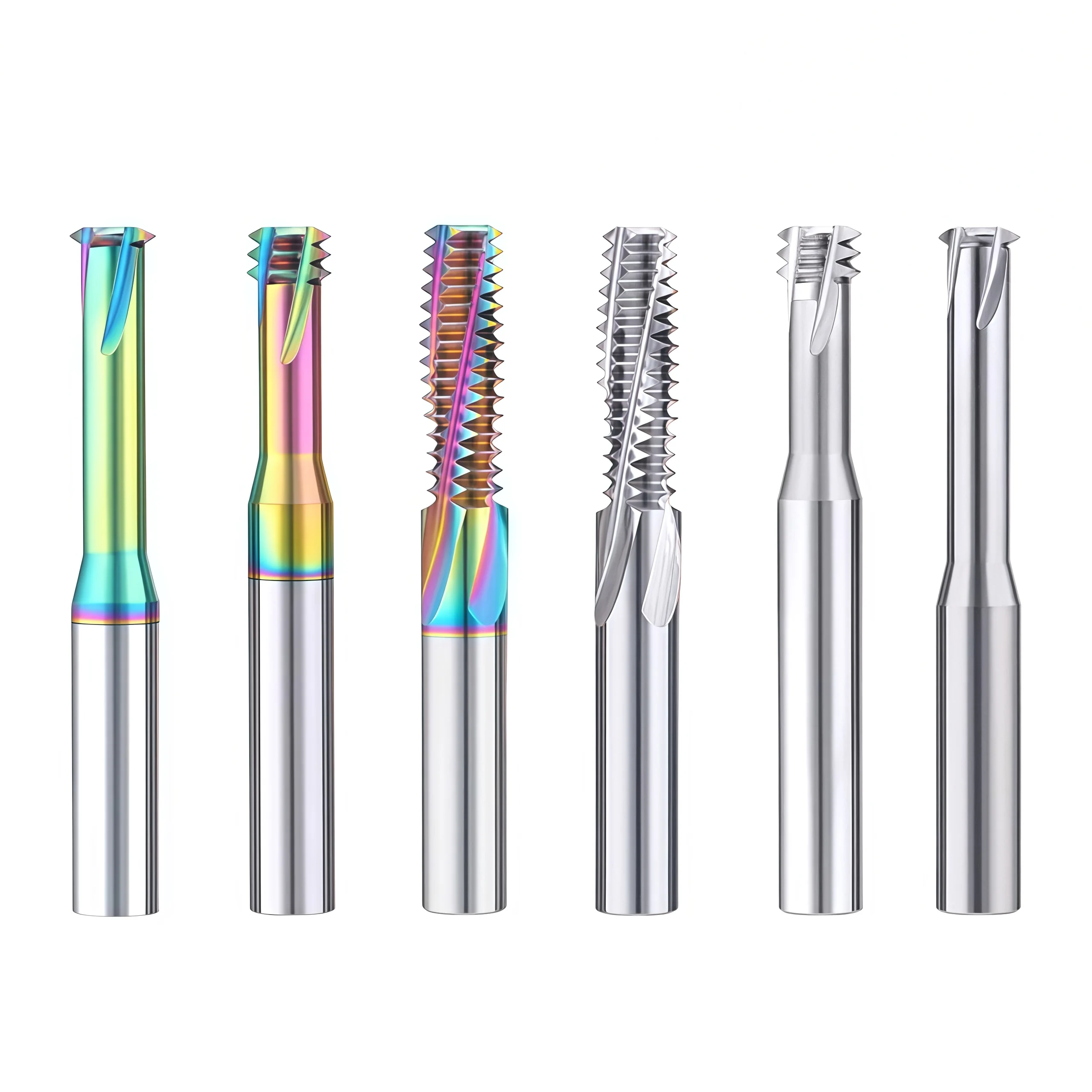
DLC-coated solid carbide thread mills for precision CNC threading in aluminum and non-ferrous materials, available in single-form, 3-tooth and full-profile configurations for low-friction cutting and reliable thread quality.
Product Configuration
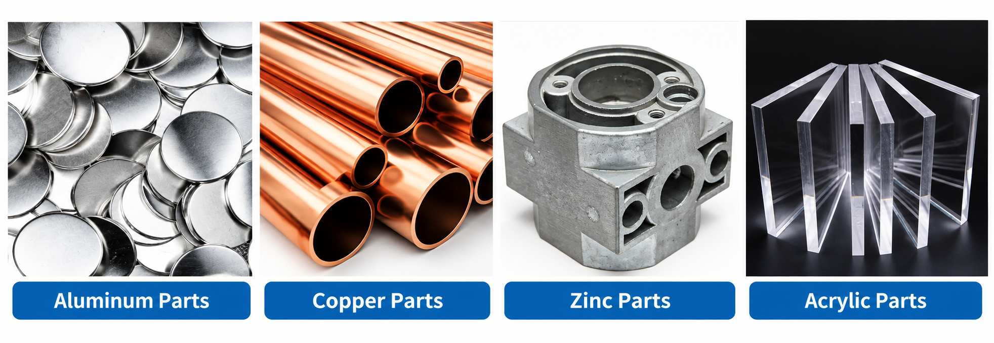
Matières premièresAluminum, copper, zinc and selected acrylic applications.
Une qualité constante
Une géométrie constante d'une commande à l'autre.
Commandes flexibles
Petits lots et formats variés disponibles.
Assistance OEM
Marquage, étiquettes et emballages personnalisés.
Modèles standard et sur mesure
Dimensions standard et configurations sur mesure.
DLC-Coated Solid Carbide Thread Mill Series for Aluminum & Non-Ferrous Metals
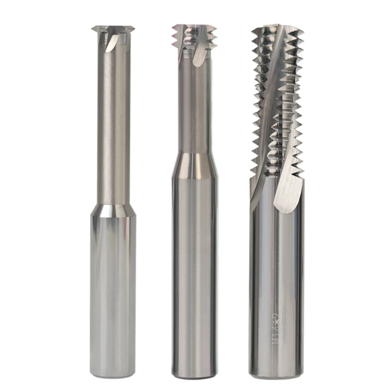
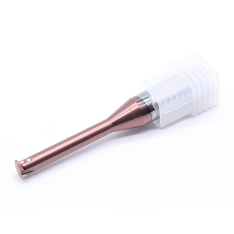
This DLC-coated solid carbide thread mill series is developed for precision CNC threading in aluminum, copper and other non-ferrous materials. Single-form, 3-tooth and full-profile configurations provide different options for thread depth, pitch requirements and production efficiency. The low-friction DLC surface helps reduce material adhesion, while precision-ground carbide geometry supports clean thread profiles and stable CNC thread milling.
Key Configuration
DLC Coating
Low-friction surface for aluminum and non-ferrous machining.
Three Configurations
Single-Form / 3-Tooth / Full-Profile.
Solid Carbide
Precision-ground geometry for CNC thread milling.
Product Advantages
DLC coating and precision-ground geometry are designed for smooth chip evacuation, stable toolholding and clean thread milling in aluminum and non-ferrous materials.
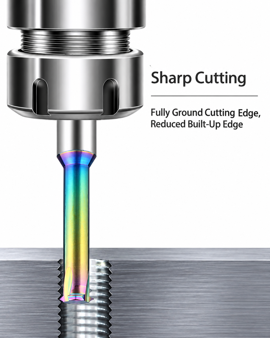
Sharp Cutting
Precision-Ground Cutting Edge
Sharp cutting geometry supports smooth cutting and clean thread formation in aluminum.
Chip Evacuation
Large Chip Flute
Open chip-groove geometry provides more space for chip evacuation during aluminum thread milling.

Stable Toolholding
Precision-Ground Round Shank
Ground cylindrical shanks support secure clamping and stable CNC thread-milling operations.

Thread Milling Applications
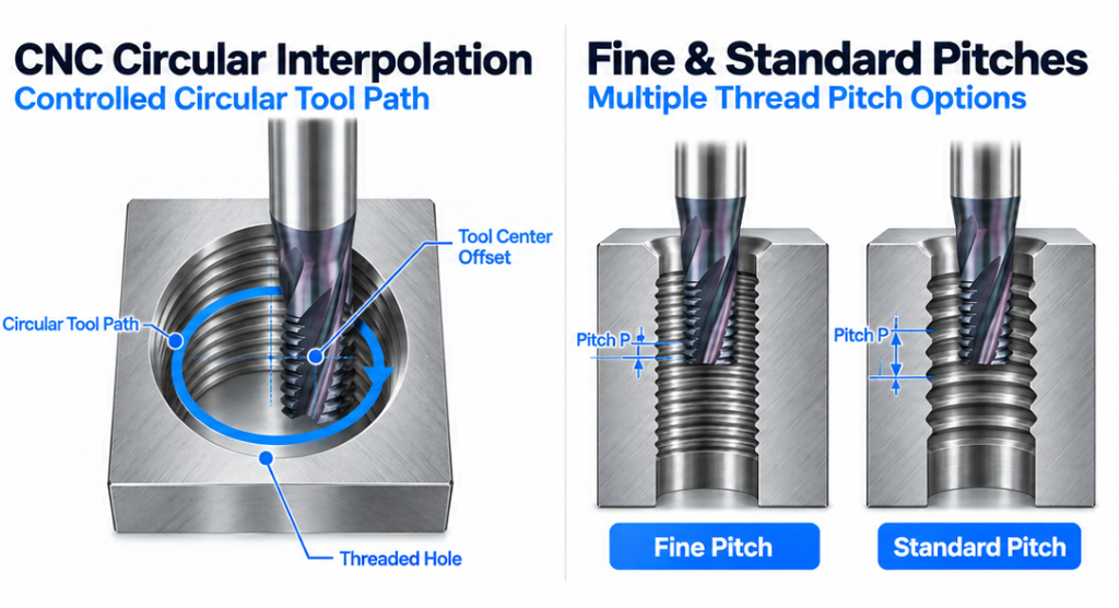
Suitable for precision internal thread milling, blind-hole threading, fine and standard pitches, and CNC circular interpolation.

Application Materials
Suitable for aluminum, copper, zinc and selected acrylic components, with tool geometry and cutting conditions matched to the specific material and thread requirement.
Material Note:
For steel, stainless steel and hardened materials, select a different carbide and coating configuration.
Product & Coating Details
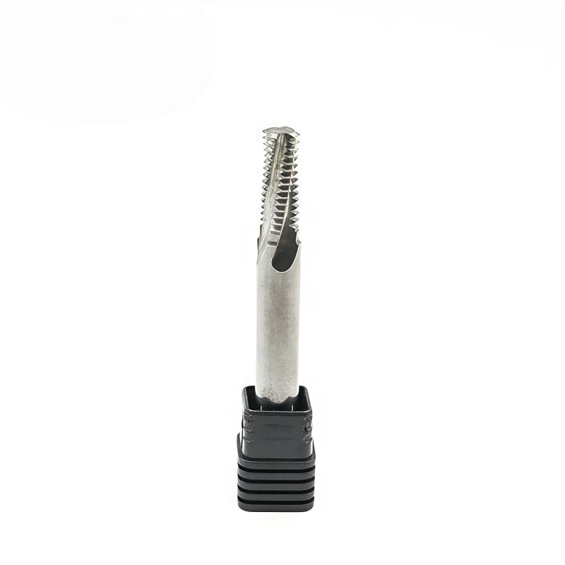
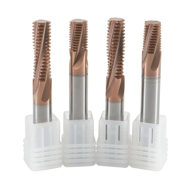
Single-form, 3-tooth and full-profile DLC-coated thread mill configurations for aluminum and non-ferrous CNC threading applications.
Need help selecting the right thread style, pitch or cutter type? Read our Thread Mill Selection Guide.
Tool Nomenclature & Dimensions
Reference nomenclature for DLC-coated solid carbide thread mills for aluminum and non-ferrous materials. The same dimensional symbols are used across the single-form, 3-tooth and full-profile configurations. All dimensions in the size tables are listed in millimeters.
| SYMBOL | DIMENSION | DESCRIPTION |
|---|---|---|
| P | Thread Pitch | Pitch matched to the required metric thread |
| d / d1 | Cutting Diameter | Thread-milling cutting-section diameter |
| L1 | Clearance / Cutting Length | Working reach according to the selected configuration |
| D | Diamètre de la tige | Cylindrical clamping diameter |
| L | Longueur totale | Longueur totale de l'outil |
| F | Nombre de flûtes | Number of cutting flutes; varies by tool size and configuration |
Configuration technique
| PARAMÈTRE | CARACTÉRISTIQUES TECHNIQUES |
|---|---|
| Matériau de l'outil | Solid Carbide |
| Revêtement | DLC (Diamond-Like Carbon) |
| Available Configurations | Single-Form / 3-Tooth / Full-Profile |
| Thread Standard | Metric Standard Series / Custom Requirements by Review |
| Matières premières | Aluminum / Copper / Brass / Selected Non-Ferrous Alloys |
| Machining Method | CNC Circular / Helical Interpolation |
| Coolant / Chip Control | Air Blow / Oil Mist / Suitable Non-Ferrous Cutting Fluid |
| Options personnalisées | Pitch / Diameter / L1 / Shank / Overall Length / Thread-Tooth Configuration / Geometry / Marking / Packaging |
Standard Size Matrix
Choose the required thread mill configuration below. The series includes single-form, 3-tooth and full-profile designs, each providing a different balance of thread-depth flexibility, machining efficiency and pitch-specific production capability.

Single-Form Thread Mill Sizes
Single-form geometry uses one thread-form cutting section, providing greater flexibility for different thread depths and compatible thread diameters.
| THREAD SIZE | P Pitch | d1 Cutting Dia. | L1 Clearance | D Dia. de la tige. | L Longueur totale | F Flûtes |
|---|---|---|---|---|---|---|
| M0.8 | 0.20 | 0.55 | 1.5 | 4.0 | 50 | 3 |
| M0.9 | 0.225 | 0.625 | 1.8 | 4.0 | 50 | 3 |
| M1 | 0.25 | 0.70 | 3.1 | 4.0 | 50 | 3 |
| M1.2 | 0.25 | 0.90 | 3.6 | 4.0 | 50 | 3 |
| M1.4 | 0.30 | 1.05 | 4.2 | 4.0 | 50 | 3 |
| M1.6 | 0.35 | 1.20 | 4.8 | 4.0 | 50 | 3 |
| M1.8 | 0.35 | 1.40 | 5.6 | 4.0 | 50 | 3 |
| M2.0 | 0.40 | 1.55 | 6 | 4.0 | 50 | 3 |
| M2.5 | 0.45 | 1.96 | 7.5 | 4.0 | 50 | 3 |
| M3 | 0.50 | 2.35 | 9 | 4.0 | 50 | 3 |
| M3.5 | 0.60 | 2.75 | 9 | 4.0 | 50 | 3 |
| M4 | 0.70 | 3.15 | 12 | 4.0 | 50 | 3 |
| M5 | 0.80 | 3.90 | 15 | 4.0 | 50 | 3 |
| M6 | 1.00 | 4.80 | 18 | 6.0 | 50 | 3 |
| M8 | 1.25 | 6.00 | 24 | 6.0 | 50 | 4 |
| M10 | 1.50 | 7.70 | 28 | 8.0 | 60 | 4 |
| M12 | 1.50 | 9.40 | 30 | 10.0 | 75 | 4 |
| M12 | 1.75 | 9.60 | 30 | 10.0 | 75 | 4 |
| M14 | 2.00 | 10.00 | 36 | 10.0 | 75 | 4 |
| M16 | 2.00 | 12.00 | 38 | 12.0 | 75 | 4 |
| M18 | 2.50 | 14.50 | 48 | 16.0 | 100 | 4 |
| M20 | 2.50 | 16.00 | 48 | 16.0 | 100 | 4 |
| M24 | 3.00 | 16.00 | 48 | 16.0 | 100 | 4 |
View 3-Tooth Thread Mill Size Table
Three-tooth thread mill configurations provide an intermediate option between single-form flexibility and full-profile productivity, with three thread-form teeth engaging during the machining cycle.
| THREAD SIZE | P | d1 | L1 | D | L | F |
|---|---|---|---|---|---|---|
| M1.0 | 0.25 | 0.73 | 3 | 4.0 | 50 | 3 |
| M1.2 | 0.25 | 0.92 | 3.6 | 4.0 | 50 | 3 |
| M1.4 | 0.30 | 1.05 | 4.2 | 4.0 | 50 | 3 |
| M1.6 | 0.35 | 1.20 | 4.8 | 4.0 | 50 | 3 |
| M1.8 | 0.35 | 1.41 | 4.5 | 4.0 | 50 | 3 |
| M2.0 | 0.40 | 1.55 | 6 | 4.0 | 50 | 3 |
| M2.2 | 0.45 | 1.63 | 6 | 4.0 | 50 | 3 |
| M2.5 | 0.45 | 2.00 | 7.5 | 4.0 | 50 | 3 |
| M3.0 | 0.50 | 2.40 | 9 | 4.0 | 50 | 3 |
| M3.5 | 0.60 | 2.75 | 9 | 4.0 | 50 | 3 |
| M4.0 | 0.70 | 3.15 | 12 | 4.0 | 50 | 3 |
| M4.5 | 0.75 | 3.50 | 12 | 4.0 | 50 | 3 |
| M5.0 | 0.80 | 4.00 | 15 | 4.0 | 50 | 3 |
| M2.0 | 0.40 | 1.55 | 6 | 6.0 | 50 | 3 |
| M2.5 | 0.45 | 2.00 | 7.5 | 6.0 | 50 | 3 |
| M3.0 | 0.50 | 2.40 | 9 | 6.0 | 50 | 3 |
| M3.5 | 0.60 | 2.75 | 9 | 6.0 | 50 | 3 |
| M4.0 | 0.70 | 3.15 | 12 | 6.0 | 50 | 3 |
| M5.0 | 0.80 | 4.00 | 15 | 6.0 | 50 | 3 |
| M6.0 | 0.75 | 5.00 | 15 | 6.0 | 50 | 3 |
| M6.0 | 1.00 | 4.80 | 15 | 6.0 | 50 | 3 |
| M8.0 | 0.50 | 6.00 | 20 | 6.0 | 50 | 3 |
| M8.0 | 0.75 | 6.00 | 20 | 6.0 | 50 | 3 |
| M8.0 | 1.00 | 6.00 | 20 | 6.0 | 50 | 3 |
| M8.0 | 1.25 | 6.00 | 20 | 6.0 | 50 | 4 |
| M10 | 0.50 | 8.00 | 20 | 8.0 | 60 | 4 |
| M10 | 1.00 | 8.00 | 20 | 8.0 | 60 | 4 |
| M10 | 1.25 | 8.00 | 25 | 8.0 | 60 | 4 |
| M10 | 1.50 | 8.00 | 25 | 8.0 | 60 | 4 |
| M10 | 1.50 | 8.20 | 30 | 10.0 | 75 | 4 |
| M12 | 1.00 | 10.00 | 37 | 10.0 | 75 | 4 |
| M12 | 1.50 | 10.00 | 30 | 10.0 | 75 | 4 |
| M12 | 1.75 | 10.00 | 30 | 10.0 | 75 | 4 |
| M14 | 1.00 | 10.00 | 37 | 10.0 | 75 | 4 |
| M14 | 1.50 | 10.00 | 37 | 10.0 | 75 | 4 |
| M14 | 2.00 | 10.00 | 37 | 10.0 | 75 | 4 |
| M16 | 1.00 | 12.00 | 37 | 12.0 | 75 | 4 |
| M16 | 1.50 | 12.00 | 37 | 12.0 | 75 | 4 |
| M16 | 2.00 | 11.50 | 37 | 12.0 | 75 | 4 |
| M20 | 1.50 | 15.80 | 45 | 16.0 | 100 | 4 |
| M20 | 2.00 | 15.80 | 45 | 16.0 | 100 | 4 |
| M20 | 2.50 | 16.00 | 45 | 16.0 | 100 | 4 |
| M24 | 3.00 | 16.00 | 45 | 16.0 | 100 | 4 |
View Full-Profile Thread Mill Size Table
Pitch-specific full-profile geometry uses multiple thread-form teeth for efficient repeat production of confirmed metric thread specifications.
| THREAD SIZE | P | d | L1 | D | L | F |
|---|---|---|---|---|---|---|
| M3 | 0.50 | 2.35 | 6.0 | 4.0 | 50 | 4 |
| M4 | 0.70 | 3.15 | 8.0 | 4.0 | 50 | 4 |
| M5 | 0.50 | 4.00 | 10 | 4.0 | 50 | 3 |
| M5 | 0.75 | 4.00 | 10 | 4.0 | 50 | 3 |
| M5 | 0.80 | 4.00 | 10 | 4.0 | 50 | 4 |
| M6 | 0.75 | 4.80 | 12 | 6.0 | 60 | 3 |
| M6 | 1.00 | 4.80 | 12 | 6.0 | 60 | 4 |
| M8 | 0.50 | 6.00 | 16 | 6.0 | 60 | 3 |
| M8 | 0.75 | 6.00 | 16 | 6.0 | 60 | 3 |
| M8 | 1.00 | 6.00 | 16 | 6.0 | 60 | 3 |
| M8 | 1.25 | 6.00 | 16 | 6.0 | 60 | 3 |
| M10 | 1.00 | 8.00 | 21 | 8.0 | 60 | 4 |
| M10 | 1.25 | 8.00 | 21 | 8.0 | 60 | 4 |
| M10 | 1.50 | 8.00 | 21 | 8.0 | 60 | 4 |
| M12 | 0.50 | 10.00 | 24 | 10.0 | 75 | 4 |
| M12 | 0.75 | 10.00 | 24 | 10.0 | 75 | 4 |
| M12 | 1.00 | 10.00 | 24 | 10.0 | 75 | 4 |
| M12 | 1.50 | 10.00 | 24 | 10.0 | 75 | 4 |
| M12 | 1.75 | 9.90 | 24 | 10.0 | 75 | 4 |
| M14 | 1.00 | 12.00 | 28 | 12.0 | 75 | 4 |
| M14 | 1.50 | 12.00 | 28 | 12.0 | 75 | 4 |
| M14 | 2.00 | 12.00 | 30 | 12.0 | 75 | 4 |
| M16 | 1.50 | 14.00 | 32 | 14.0 | 100 | 4 |
| M16 | 2.00 | 13.00 | 32 | 14.0 | 100 | 4 |
| M18 | 2.50 | 14.80 | 38 | 16.0 | 100 | 4 |
| M20 | 1.50 | 16.00 | 38 | 16.0 | 100 | 4 |
| M20 | 2.50 | 16.00 | 40 | 16.0 | 100 | 4 |
| M24 | 3.00 | 16.00 | 42 | 16.0 | 100 | 4 |
Recommended Starting Cutting Parameters
Exact cutting data should be selected according to the aluminum or non-ferrous alloy grade, cutter diameter, thread pitch, thread depth, selected single-form / 3-tooth / full-profile configuration, machine rigidity and toolholder runout.
| PARAMÈTRE | SELECTION BASIS | STARTING GUIDANCE |
|---|---|---|
| Spindle Speed | Cutting diameter / alloy grade | Use suitable high-speed conditions for carbide tooling and adjust by test cutting |
| Feed Rate | Diameter / pitch / flute count / configuration | Start conservatively and optimize after checking thread profile and chip evacuation |
| Radial Compensation | Required thread fit | Fine-adjust the CNC interpolation radius according to measured thread size |
| Chip Evacuation | Blind-hole depth / alloy | Use clean air, mist or suitable lubricant to reduce chip recutting and material adhesion |
DLC Thread Mill Application Guidance
- Material Selection: Use the DLC-coated configuration primarily for aluminum and compatible non-ferrous materials.
- Single-Form: Choose when greater flexibility across compatible thread diameters or varying thread depths is required.
- 3-Tooth: Choose the three-tooth configuration as an intermediate option between single-form flexibility and full-profile production efficiency.
- Full-Profile: Choose pitch-specific multiple-tooth geometry for efficient repeat production of confirmed metric thread specifications.
- Flûte Compte : The number of cutting flutes varies by tool size and configuration; confirm the F value in the applicable size table.
- Thread Compensation: Fine-adjust the CNC interpolation radius according to the measured thread size and required fit.
- Toolholding: Use a clean, low-runout precision holder matched to shank diameter D.
- Chip Control: Maintain effective chip evacuation to reduce aluminum recutting and material adhesion and to preserve the low-friction benefit of the DLC-coated cutting surface.
Thread Mill Selection Resources
Not sure which thread mill matches your thread standard, pitch, diameter or machining application? Use our practical selection guide to compare thread specifications, tool styles and machining requirements before selecting a cutter.
DLC-Coated Solid Carbide Thread Mill Customization
Single-form, 3-tooth and full-profile thread mill configurations can be customized for CNC threading of aluminum, copper and selected non-ferrous materials. Thread pitch, cutting diameter, clearance length, shank diameter, overall length, thread-tooth configuration, thread-profile geometry, cutting-edge preparation and DLC coating can be reviewed according to the required thread specification, thread depth, prepared-hole diameter, workpiece alloy and machining conditions.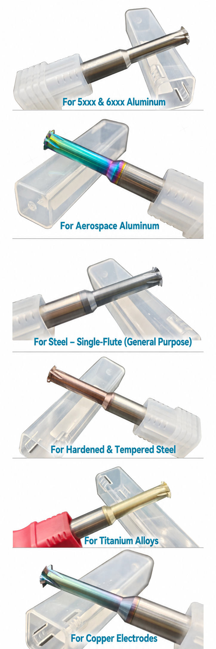

| PARAMÈTRE | CAPACITÉS DE FABRICATION |
|---|---|
| Thread Mill Configuration | Single-form, 3-tooth and full-profile configurations can be reviewed according to thread pitch, required flexibility, thread depth, machining cycle and production requirements |
| Thread Standard | Standard metric thread configurations are available, while non-standard thread requirements can be reviewed according to the supplied drawing or thread specification |
| Thread Pitch P | Standard and selected non-standard pitches can be reviewed according to thread size, thread-tooth configuration and required thread profile |
| Cutting Diameter d / d1 | Standard and custom cutting diameters can be selected according to nominal thread size, prepared-hole diameter, thread geometry and available interpolation clearance |
| Clearance Length L1 | Clearance length can be adjusted according to required thread depth, blind-hole depth and workpiece access while minimizing unnecessary tool overhang |
| Shank Diameter D | Standard cylindrical shank diameters and selected custom shank configurations can be reviewed according to precision holder and collet requirements |
| Overall Length L | Standard overall lengths and long-reach configurations can be reviewed for deeper threads and restricted-access applications |
| Single-Form Geometry | Single-form cutting geometry uses one thread-form section and is suitable where thread-depth flexibility and broader application versatility are required |
| 3-Tooth Geometry | Three thread-form cutting teeth provide an intermediate configuration between single-form flexibility and full-profile productivity, with selection based on pitch, thread depth and machining-cycle requirements |
| Full-Profile Geometry | Pitch-specific multiple cutting teeth can be configured for efficient repeat machining of confirmed thread specifications |
| Chip-Groove Design | Chip-groove geometry can be reviewed according to aluminum chip characteristics, blind-hole conditions, cutter diameter and selected thread mill configuration |
| Une préparation à la pointe de la technologie | Cutting-edge preparation and relief geometry can be adjusted to support low cutting resistance and stable machining in aluminum and other non-ferrous materials |
| DLC Coating | DLC coating is available for applications where reduced friction, lower material adhesion and improved resistance to built-up edge are required |
| Matériaux des pièces à usiner | Primarily aluminum alloys, copper, brass and selected non-ferrous materials; final geometry should be confirmed according to the exact alloy |
| Tolérance dimensionnelle | Drawing-defined requirements for pitch, cutting diameter, L1, D, L, thread-profile geometry, runout and other critical dimensions can be reviewed before production |
Services OEM et de marque de distributeur
OEM manufacturing and private-label supply options are available for distributors, tooling brands and repeat-production customers. Product identification, thread information, configuration type, DLC coating presentation, labels and protective packaging can be configured according to the approved thread mill specification and order requirements.

Gravure au laser
Custom logos, thread size, pitch, product code, configuration type, dimensions and batch identification can be laser marked according to available shank space.
Étiquettes et emballages personnalisés
Protective tubes, specification labels, thread-size identification, configuration identification, colored packaging and private-label packaging can be reviewed for distributor and OEM programs.
Trial & Repeat Supply
Standard-size trials, customized samples, repeat orders and scheduled supply programs can be reviewed according to thread mill configuration, dimensions, DLC coating and packaging requirements.
Processus technique
A structured review process is used to confirm standard, customized and OEM DLC-coated thread mill requirements before production.
Demande de renseignements
Submit thread size, pitch, thread depth, hole information, workpiece alloy, dimensions, preferred configuration and quantity.
Ingénierie
Review single-form, 3-tooth or full-profile geometry, P, d / d1, L1, D, L, cutting-edge preparation and DLC coating requirements.
Commercial
Confirm quotation, MOQ, sample quantity, customization conditions, production schedule and delivery terms.
Production
Carbide blank preparation, CNC grinding, thread-profile formation, cutting-edge preparation, DLC coating and laser marking.
Contrôle qualité
Inspect thread geometry, critical dimensions, runout, cutting-edge condition, DLC coating appearance and product identification.
Qualité, contrôle et livraison
Our DLC-coated solid carbide thread mills for aluminum and non-ferrous materials are controlled through carbide material verification, precision CNC grinding, in-process dimensional inspection, cutting-edge review, DLC coating inspection and final product checking. Single-form, 3-tooth and full-profile configurations are inspected according to the applicable thread specification, tool dimensions and approved production requirements before protective packing.

Contrôle qualité en trois étapes
Inspection checkpoints are arranged throughout the manufacturing process to support thread-geometry consistency, dimensional stability, cutting-edge quality and repeat-order consistency across single-form, 3-tooth and full-profile thread mill configurations.
Contrôle des entrées de marchandises
Carbide substrate specification, blank diameter, blank length and supplied material information are checked against the confirmed thread mill production requirements before CNC grinding.
Contrôle du broyage en cours de fabrication
Thread pitch, cutting diameter, clearance length, shank diameter, overall length, flute count, chip-groove geometry and single-form / 3-tooth / full-profile cutting geometry are monitored during precision CNC grinding.
Inspection finale des outils
Finished thread mills are reviewed for specified dimensions, radial runout, thread-form geometry, cutting-edge condition, flute surfaces, DLC coating appearance, laser marking and packing identification.
Caractéristiques clés d'inspection
Inspection requirements are confirmed according to the applicable single-form, 3-tooth or full-profile thread mill specification, standard size configuration or approved custom drawing.
| POINT D'INSPECTION | POINT FORT : LE CONTRÔLE | BASE DE CONFIRMATION |
|---|---|---|
| Thread Pitch (P) | Pitch spacing and thread-form consistency | Specified metric thread pitch or approved drawing |
| Cutting Diameter (d / d1) | Cutting-section diameter and dimensional consistency | Selected standard size or approved drawing |
| Clearance Length (L1) | Working reach and clearance section | Standard configuration, thread depth or approved drawing |
| Shank Diameter (D) | Clamping diameter and shank surface condition | Standard size specification or approved drawing |
| Longueur totale (L) | Longueur totale de l'outil | Matrice aux dimensions standard ou plan homologué |
| Thread Mill Configuration | Single-form, 3-tooth or full-profile tooth geometry | Approved product configuration and required thread specification |
| Flute Count (F) | Number of cutting flutes and flute consistency | Applicable size-table specification |
| Chip-Groove Profile | Chip space, groove form and grinding consistency | Configuration de fabrication approuvée |
| Cutting Edge & DLC Coating | Cutting-edge condition, visible grinding defects and coating appearance | Confirmed aluminum / non-ferrous application and DLC-coated configuration |
| Marquage et identification | Thread size, pitch, tool code, configuration and batch information where applicable | Confirmation de la commande et spécifications d'emballage |
Mesure et traçabilité des lots
Optical measuring systems, tool inspection equipment and appropriate dimensional gauges are selected according to the thread mill configuration and feature being checked.
Mesure optique
Dimensional and profile review of single-form, 3-tooth or full-profile cutting geometry and critical tool dimensions.
Vérification du faux-rond
Concentricity between the thread-milling cutting section and precision shank is reviewed according to the agreed product requirement.
Edge & Coating Inspection
Magnified review of thread-form teeth, cutting edges, chip grooves, flute surfaces and DLC coating appearance.
Identification des lots
Order, thread specification, tool configuration, product code and batch information can be linked where required for repeat supply.
Procédé d'emballage de protection
Finished DLC-coated thread mills are individually protected to reduce contact with precision-ground thread-form teeth, cutting edges and coated surfaces while supporting clear configuration and specification identification during storage and transportation.

Emballage pour commandes en gros et exportation
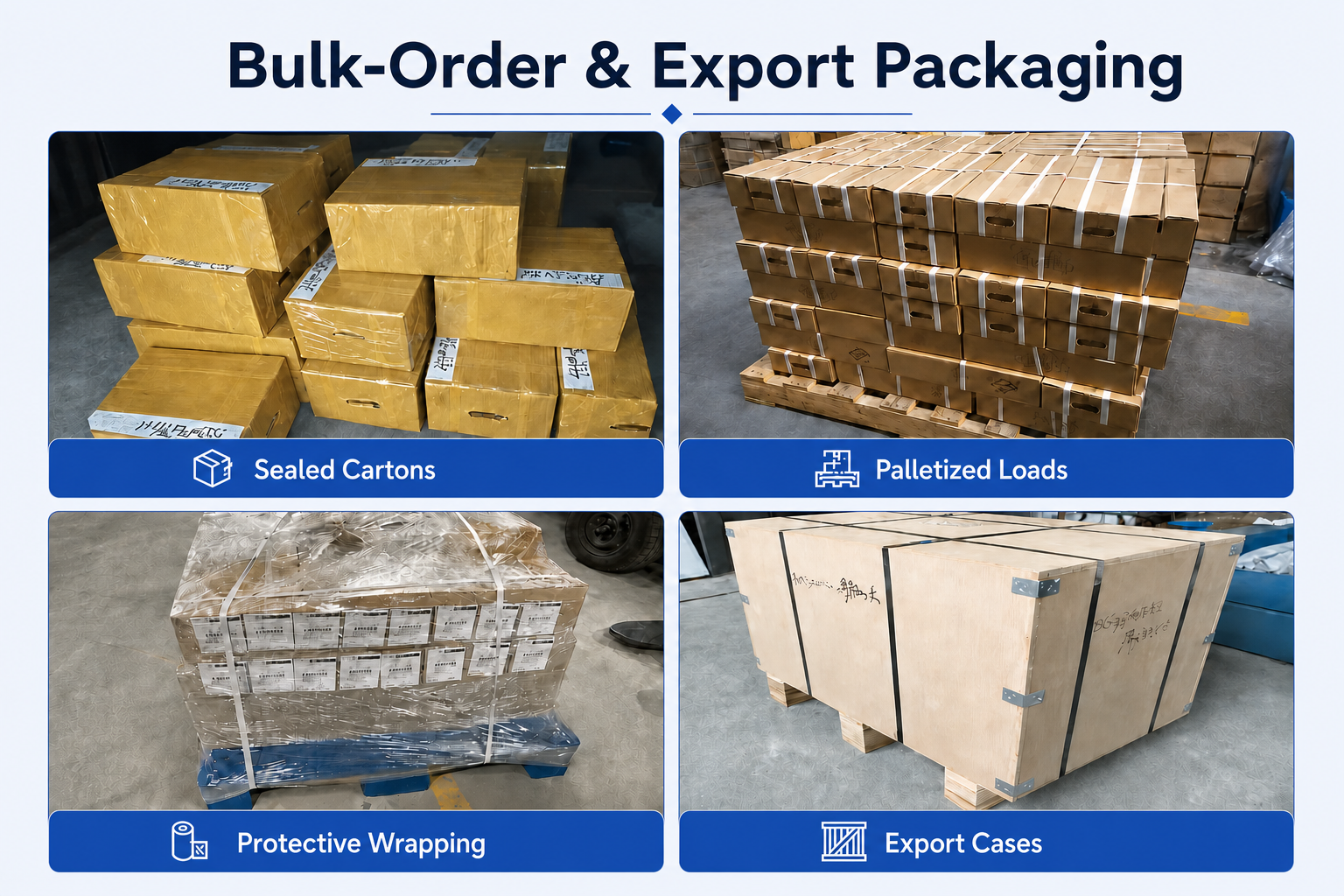
Les expéditions en vrac peuvent être organisées à l'aide de cartons renforcés, d'emballages de protection, d'un chargement sur palettes ou de caisses d'exportation, en fonction de la quantité commandée, du poids de l'envoi et des exigences de transport convenues.
Coordination des livraisons
In-stock standard configurations can normally be prepared for shipment within 1–3 days. Lead time for customized DLC-coated thread mills is confirmed after thread size, pitch, single-form / 3-tooth / full-profile configuration, dimensions, quantity, marking and packaging requirements are approved. Courier, air, sea or customer-designated shipping options can be reviewed according to shipment size and destination.
FAQ et téléchargements
Review common selection, application and ordering questions for DLC-coated solid carbide thread mills for aluminum and non-ferrous metals, including single-form, 3-tooth and full-profile configurations.
FAQ sur les produits et leurs applications
Application guidance for DLC-coated carbide thread milling in aluminum, copper, brass and other selected non-ferrous materials.
Why use a DLC-coated solid carbide thread mill for aluminum?
DLC coating provides a low-friction surface suited to aluminum and other non-ferrous materials. It helps reduce material adhesion and built-up edge around the cutting profile, supporting cleaner thread surfaces and more stable machining when the geometry and cutting parameters are properly matched to the alloy.
What are the differences between single-form, 3-tooth and full-profile thread mills?
A single-form thread mill uses one thread-form cutting section and offers greater flexibility for compatible thread diameters and varying thread depths. A 3-tooth thread mill uses three thread-form teeth and provides an intermediate option between flexibility and machining efficiency. A full-profile thread mill uses multiple pitch-specific teeth and is suited to repeat production of a confirmed thread specification.
When should I choose a 3-tooth DLC carbide thread mill?
A 3-tooth configuration can be selected when an intermediate balance between single-form flexibility and full-profile productivity is required. Tool selection should consider thread pitch, thread depth, cutter diameter, required cycle time, workpiece alloy and available machining clearance.
Can a single-form thread mill machine different thread diameters with the same pitch?
In suitable applications, a single-form thread mill can machine different compatible thread diameters that share the same pitch, provided the cutting diameter, thread geometry, prepared-hole size and available interpolation clearance are suitable. The finished thread diameter is controlled through the CNC interpolation path.
Are DLC-coated thread mills suitable for blind-hole threading in aluminum?
Yes, provided the prepared-hole depth, required thread depth, clearance length and chip-removal conditions are suitable. Blind-hole aluminum threading requires effective chip evacuation to reduce chip recutting and material adhesion. Clean air, oil mist or a suitable non-ferrous cutting fluid can be selected according to the application.
What non-ferrous materials can DLC-coated thread mills machine?
The DLC-coated series is primarily intended for aluminum alloys and can also be reviewed for copper, brass and selected non-ferrous materials. Because non-ferrous alloys vary in composition, hardness and chip behavior, the exact geometry and cutting conditions should be confirmed for the workpiece material.
Should I use this DLC-coated thread mill series for steel or stainless steel?
This DLC-coated series is primarily positioned for aluminum and compatible non-ferrous materials. Steel, stainless steel and hardened materials normally require a different carbide, cutting-edge and coating configuration, so those applications should be reviewed separately.
FAQ sur les commandes et la personnalisation
Information for distributors, tooling brands and industrial buyers sourcing standard or custom DLC-coated thread mills.
What information is required to select a custom DLC thread mill for aluminum?
Please provide the thread standard, nominal thread size, pitch, prepared-hole diameter, required thread depth, blind-hole or through-hole condition, aluminum or non-ferrous alloy grade, required tool dimensions, preferred single-form / 3-tooth / full-profile configuration and expected order quantity. A component drawing is recommended for non-standard applications.
Can you customize single-form, 3-tooth and full-profile DLC thread mills?
Yes. Thread pitch, cutting diameter, clearance length, shank diameter, overall length, tooth configuration, flute count, thread-profile geometry, chip grooves, cutting-edge preparation, DLC coating, laser marking and packaging can be reviewed according to the machining requirement.
Are OEM marking and private-label packaging available for DLC thread mills?
Yes. Logos, thread size, pitch, tool codes, configuration identification and batch information can be laser marked where shank space permits. Custom labels, protective tubes and private-label packaging can also be reviewed for distributor and OEM orders.
What is the lead time for DLC-coated solid carbide thread mills?
In-stock standard configurations can normally be prepared for shipment within 1–3 days. Customized DLC-coated thread mills require confirmation of the thread specification, tooth configuration, dimensions, quantity, marking and packaging requirements before the production lead time is confirmed.
Téléchargements techniques
Access carbide tooling references for thread mill selection and CNC cutting-data review.
Solid Carbide End Mills Catalog
Product families, carbide tooling configurations and reference size information.
Threading & Reaming Tools Cutting Data
General starting references for carbide threading tools and cutting-parameter adjustment.
DLC thread-milling parameters should be confirmed according to alloy grade, thread pitch, cutter diameter, thread depth, selected single-form / 3-tooth / full-profile configuration, flute count, tool overhang, holder runout and machine rigidity.
Related Guides & Thread Mill Resources
Explore practical thread-milling selection guides and related solid carbide thread mill series for different thread standards, materials and machining requirements.
Selection guidance for thread standards, pitch, tool style, diameter, depth and workpiece material.
Compare flexibility, thread size range, breakage risk and typical machining applications.
Browse metric, inch, UNC/UNF, single-form, full-profile and application-specific thread mill series.
Vous avez besoin d'informations sur les tailles, les prix ou les options personnalisées ?
Veuillez nous indiquer le type d'outil requis, ses dimensions, les quantités, le matériau de la pièce à usiner ainsi que toute exigence spécifique à un équipementier ou toute demande sur mesure. Nous vous confirmerons les caractéristiques techniques adaptées, la disponibilité, le délai de livraison et les détails du devis.
Les croquis, les listes de dimensions et les photos de référence sont les bienvenus.