6D–10D Indexable U-Drill with Integrated Pilot Drill
Deep-hole indexable U-drill with a leading pilot drill and peripheral carbide inserts for CNC holemaking. The series covers 6×D, 8×D and 10×D depth classes. Select the complete body by finished hole diameter and required depth, then confirm the matching pilot, inserts, shank and coolant connection.
Key Configuration
*Series reference ranges. Confirm the diameter, pilot size and usable depth available for each body model.
For a quotation: Send the finished hole diameter, drilling depth, workpiece material, machine/holder, coolant capability and quantity. We will confirm the body, pilot and insert configuration.
جودة متسقة
Consistent geometry across repeat orders.
الطلبات المرنة
Small batches and mixed sizes available.
OEM Support
Custom marking, labels and packaging.
قياسي ومخصص
Standard sizes and custom configurations.
6D–10D Integrated Pilot U-Drill Overview
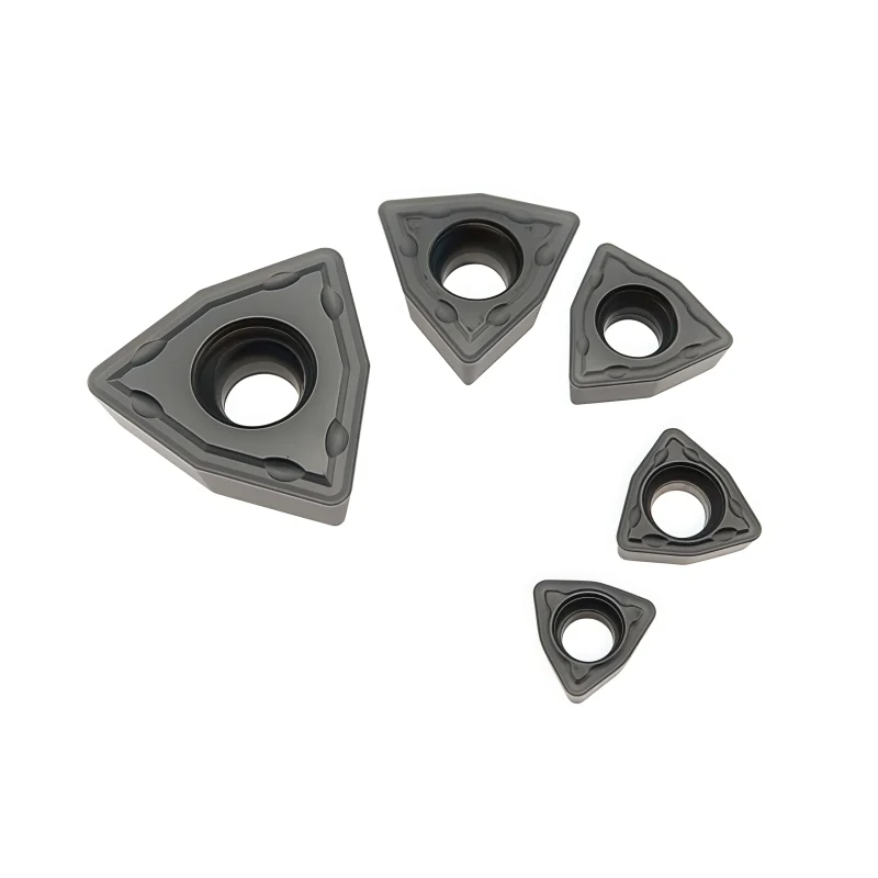
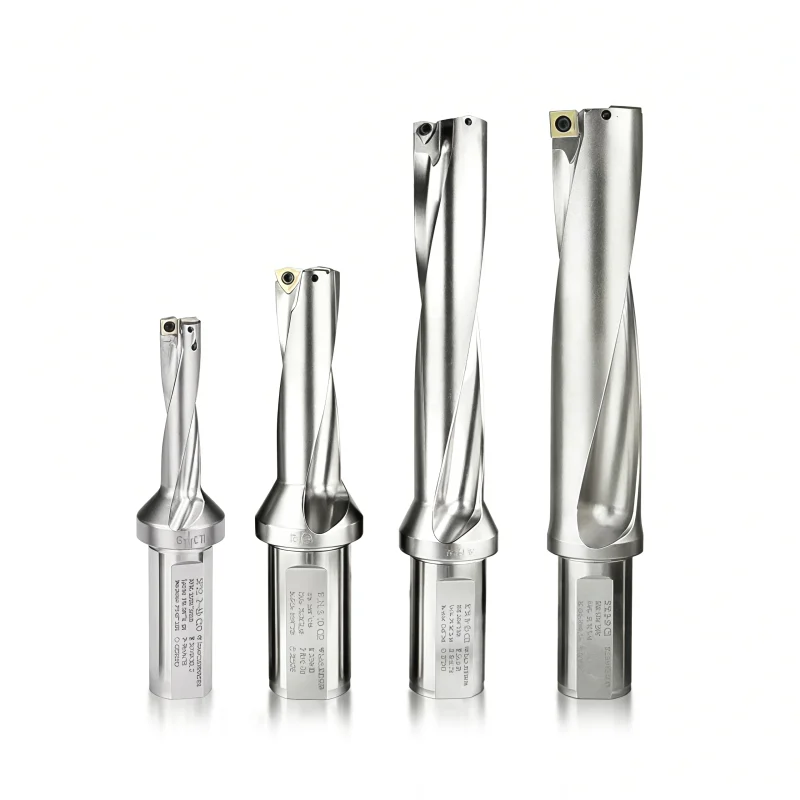
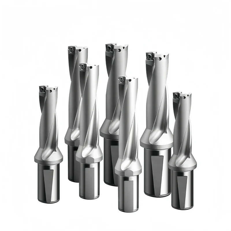
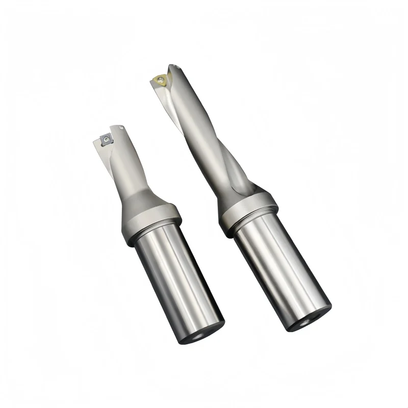
This deep-hole indexable U-drill combines a leading pilot drill with peripheral carbide inserts on one tool body. The pilot begins the cut while the outer inserts generate the specified hole diameter. For CNC lathes and machining centers, the configuration can reduce separate centering steps when the selected tool and setup allow it. Choose the 6×D, 8×D or 10×D body by finished diameter and usable drilling depth; confirm the complete assembly and coolant requirements before machining.
The series description lists a Ø14–60 mm finished-hole range and a Ø3.0–12.7 mm pilot-drill range. Confirm the available diameter, pilot and depth combinations against the model-specific chart.
Key Configuration
Application & Selection
Review the workpiece grade, hole diameter and tolerance, blind or through-hole condition, drilling depth, available coolant and machine rigidity together. Steel, stainless steel, cast iron and alloy applications require suitable cutting-element grades and verified starting data. An interrupted entry, cross-hole or angled surface needs a separate application review.
Selection sequence: finished hole diameter → required depth in mm → matching 6×D/8×D/10×D body → pilot and peripheral insert codes → shank and coolant connection → sample cut.
Product Images


U-Drill Machining Video
View the
original Reel on Instagram.
Size Chart & Specifications
The following ranges summarize the series. Confirm each body drawing for the orderable diameter, usable depth, shank and matching cutting elements.
| المعلمة | Series Information / Confirmation |
|---|---|
| Tool system | Leading pilot drill plus peripheral indexable inserts on a deep-hole body. |
| Depth class | 6×D / 8×D / 10×D stated; available combinations and usable depth by body model. |
| Finished-hole diameter | Ø14–60 mm stated series reference; verify exact orderable diameters. |
| Pilot diameter | Ø3.0–12.7 mm stated reference; match to the body and finished diameter. |
| Cutting elements | Pilot drill or head plus specified peripheral carbide inserts; grade and geometry by application. |
| Shank / machine interface | Confirm actual shank style, dimensions and holder fit on the selected drawing. |
| سائل التبريد | Through-tool provision described; connection, required pressure and flow by model and application. |
| Workpiece materials | Steel, stainless steel, alloy steel and cast iron subject to matching grade and cutting data. |
| Hole tolerance / finish | No guaranteed IT grade, straightness or Ra value established by the supplied material; validate on the actual setup. |
Dimension note: D is nominal finished-hole diameter. A 10×D designation describes a depth class; it does not prove every Ø14–60 mm size is available at 10×D.
How to Specify the Complete Tool
| Order Item | Details to Confirm |
|---|---|
| Drill body | Full model, finished diameter, 6×D/8×D/10×D version, usable drilling depth, overall length and shank. |
| Pilot component | Full code, diameter, projection, mounting method and replacement availability. |
| Peripheral inserts | Complete insert codes, quantity and position, grade, coating and chipbreaker. |
| Hardware & coolant | Screws, wrench, coolant connection and suitable supply for the chosen depth. |
| Workpiece & machine | Material grade and hardness, hole type, machine, holder, runout and entry/exit conditions. |
Starting Cutting Data & Process Checks
Set speed and feed from the approved pilot and peripheral insert recommendations for the selected workpiece. The pilot and outer cutting edges must be considered as one assembly. Verify the drilling cycle, coolant delivery and chip evacuation at the actual depth before increasing feed.
Data note: Use grade-specific speed and feed recommendations for the complete assembly. Coolant pressure, IT grade, straightness and surface finish require model-specific confirmation or a production trial.
U-Drill Customization & OEM
Share the hole diameter, drilling depth, workpiece material, machine connection and current tool reference. We can review a standard indexable U-drill configuration or an application-specific drill body, then confirm the matching insert pockets, center and peripheral inserts, coolant arrangement and order details. Available modifications depend on the approved drawing and production feasibility.
Information for a Custom Quote
Use the following checklist for a replacement body or a new drilling application. Dimensions and options are confirmed for each model.
| البند | Details to Provide |
|---|---|
| Hole & Reach | Finished hole diameter and tolerance; blind or through hole; required drilling depth in mm; entry and exit conditions. |
| Body & Holder | Existing body code or drawing, depth ratio, shank style and size, holder model and available clearance. |
| Inserts & Hardware | Pocket family, center and peripheral insert codes, grades, screw specifications and required spares. |
| التطبيق | Workpiece grade and hardness, machine type, coolant supply and current cutting conditions. |
| Order & OEM | Quantity, target delivery date, marking, packaging, drawings and inspection records required. |
| Performance Target | Hole quality, chip evacuation, insert life or cycle-time issue to be addressed; sample-trial criteria if needed. |
From Request to Approval
Fit note: Similar drill diameters or insert shapes do not establish pocket interchangeability. Verify the complete body model, insert designation and screw specification before ordering.
Send your drawing and requirements through our contact form.
U-Drill Quality Control
Quality checks are based on the approved drill-body drawing and the ordered insert configuration. State critical hole tolerances, body dimensions, coolant requirements and any reporting needs before production so the inspection scope can be agreed for the specific model.
Inspection & Documentation
The drawing and purchase specification define acceptance criteria. Confirm the inspection method, sampling level and documents needed for the order.
| Check Area | What to Confirm |
|---|---|
| Body Dimensions | Cutting diameter, usable depth, overall length, shank dimensions and drawing tolerances. |
| Insert Seats & Hardware | Center and peripheral pockets, seating faces, screw threads, required fasteners and tool fit. |
| Coolant & Condition | Specified connection and channel provision, visible damage, burrs and corrosion protection; any functional check by agreement. |
| Insert Identification | Complete insert codes, center/peripheral positions, grade and coating when inserts are included. |
| Requested Records | Dimensional report, material record, sample approval or batch identification when agreed in the order. |
Quality note: The drill body's inspection does not guarantee a finished hole tolerance or surface finish. Those results also depend on the selected inserts, workpiece, machine setup, coolant and cutting conditions; confirm them in a trial when critical.
Order & Delivery
Send a line-by-line list of drill-body codes, depth ratios and quantities. Specify whether inserts, screws and wrenches are included. Stock, minimum order quantity, sample availability and dispatch or production lead time are confirmed by configuration.
Send your model list and inspection requirements through our contact form for availability and delivery confirmation.
Product FAQs
What does “integrated pilot drill” mean?
A smaller leading drill or head starts the hole ahead of the peripheral indexable inserts. The exact pilot mounting and replacement method must be confirmed for the ordered body.
Can the tool drill to 10×D in every diameter?
Availability varies by body model. Confirm the finished diameter, usable depth and pilot/insert combination on the model-specific drawing.
Does the pilot eliminate a separate pilot-hole operation?
The integrated pilot is intended to lead the cut, but a suitable entry procedure depends on the tool design, workpiece face and machine setup. Confirm the drilling cycle before production.
Which inserts and pilot drill should I order?
Provide the full drill-body code. The pilot component, peripheral inserts, grades, screws and quantities must match that body; similar-looking parts are not automatically interchangeable.
What coolant pressure is required?
Confirm pressure and flow for the selected body, material and 6×D/8×D/10×D depth. A single pressure value should not be applied to every model.
What hole tolerance or surface finish can I expect?
The product description alone does not establish an IT grade, hole straightness or Ra value. Agree the target and verify it by trial with the chosen inserts, machine, coolant and material.
Ordering & OEM FAQs
What should I send for a quotation?
Send the finished-hole diameter and tolerance, drilling depth, workpiece grade, machine and holder, coolant capability, required quantity and any current tool code or drawing.
Can I request a different shank or pilot size?
Share the interface drawing and required pilot dimensions. Feasibility, matching insert seats, coolant connection, MOQ and lead time are confirmed for the requested configuration.
Are pilot drills, inserts and screws included?
Specify the required supply scope in the inquiry. The quotation should list the body, pilot component, peripheral inserts, screws, wrench and spare parts separately or as an agreed kit.
Can I order a sample before production quantities?
Request the complete configuration and define the test material, depth, coolant conditions and hole-quality criteria. Sample availability and timing are confirmed by model.
Related Products & Inquiry
For shorter depth ratios, compare the 2D–5D Indexable U-Drill. For model-specific dimensions and a quotation, send your hole drawing and machining conditions.
Need Sizes, Pricing or Custom Options?
Send us the required tool type, sizes, quantities, workpiece material and any OEM or custom requirements. We will confirm suitable specifications, availability, lead time and quotation details.
Drawings, size lists and reference photos are welcome.