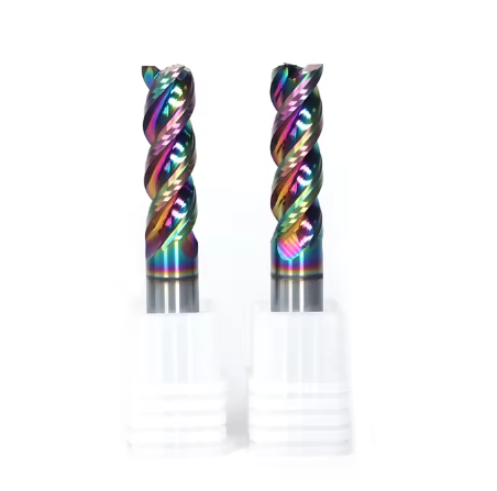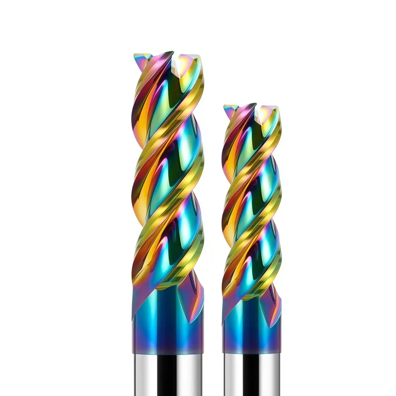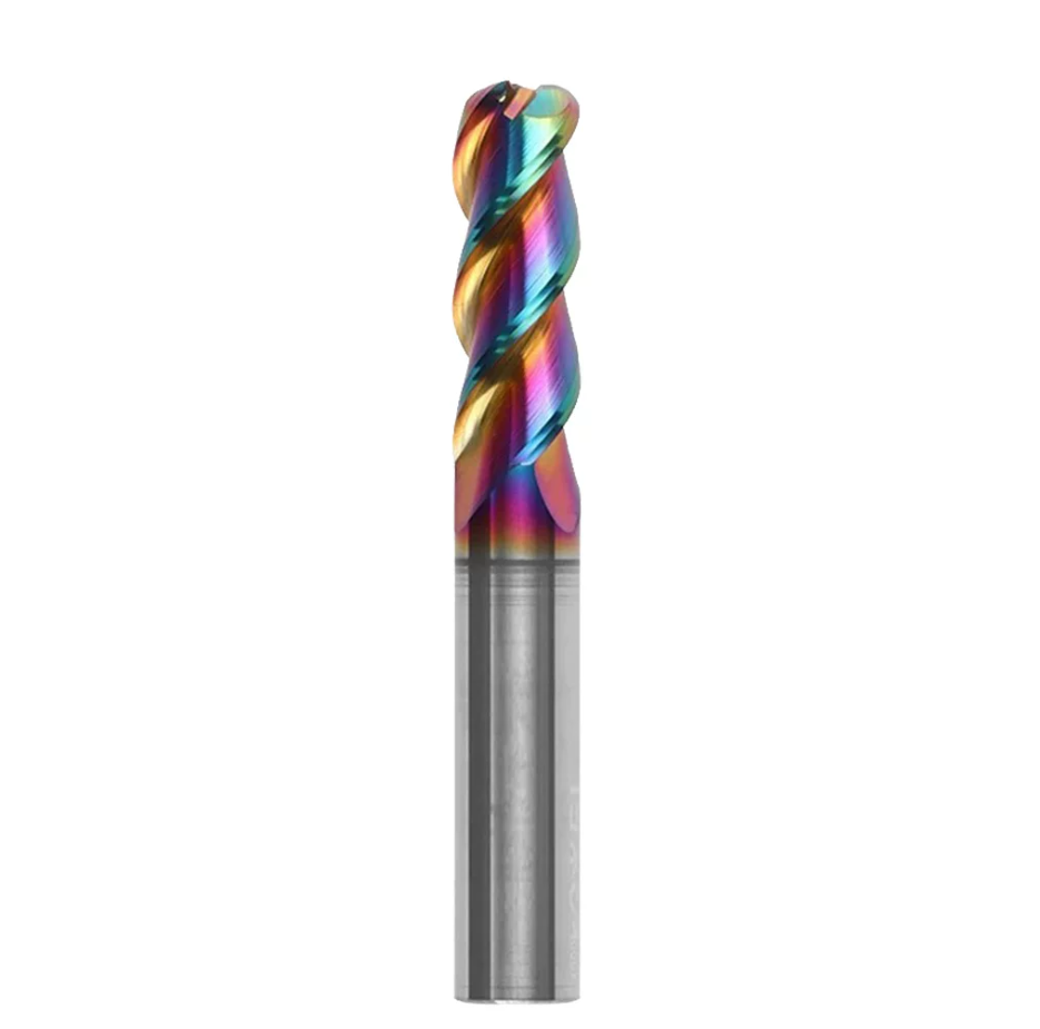
DLC-Coated Solid Carbide Corner Radius End Mill for Aluminum
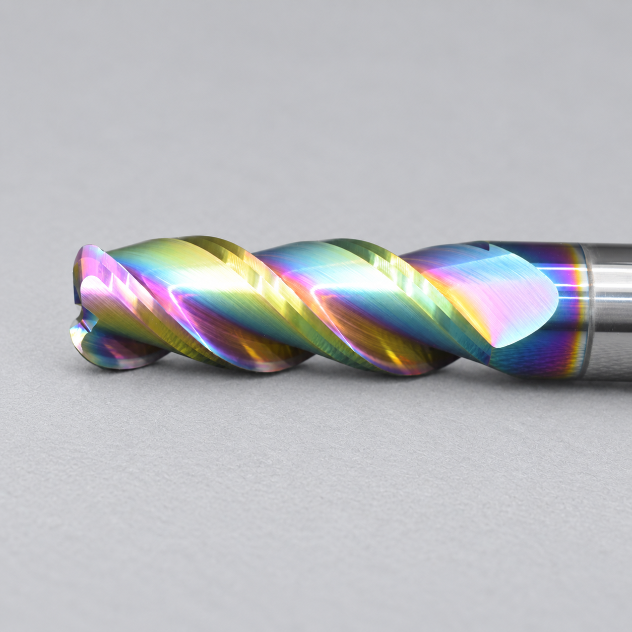
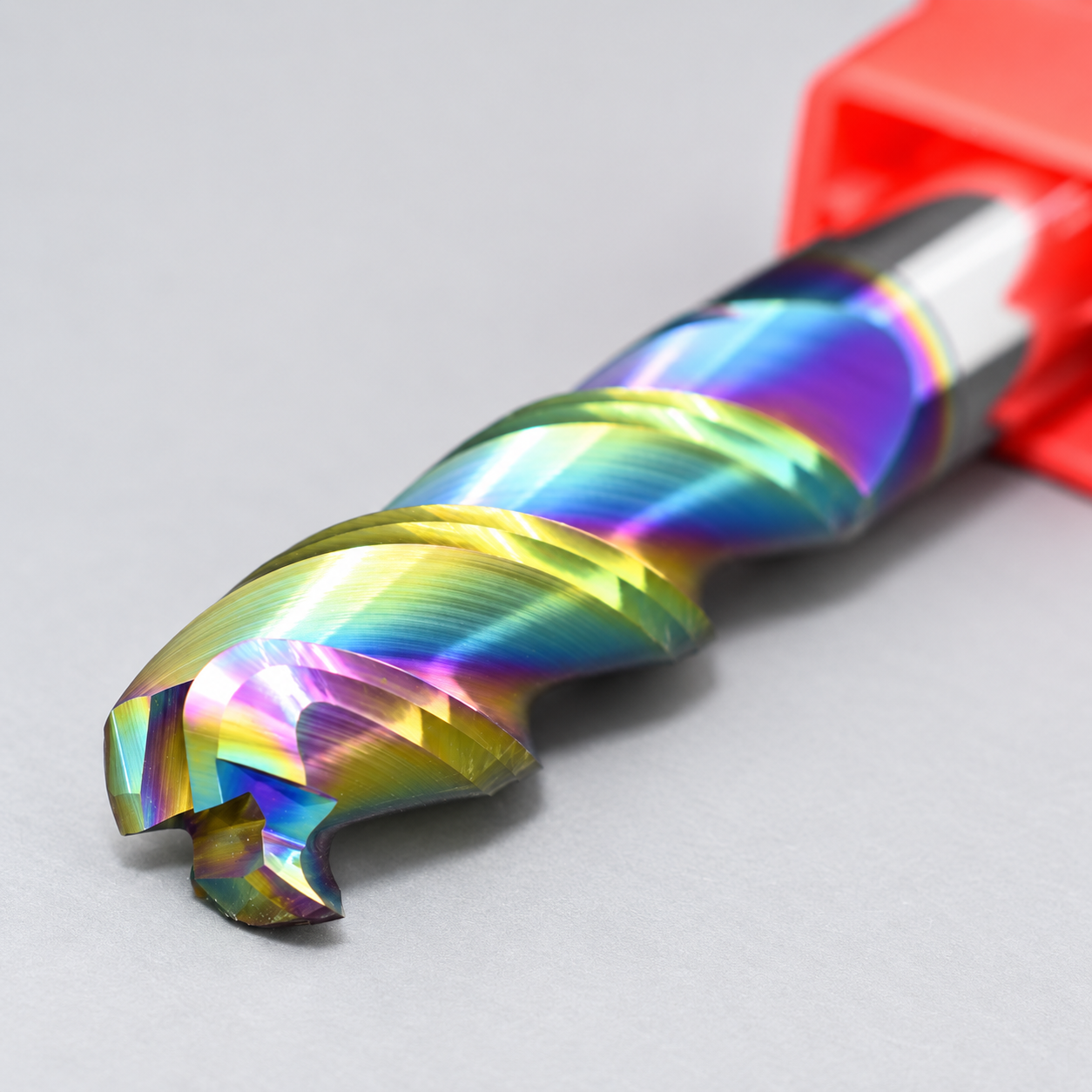
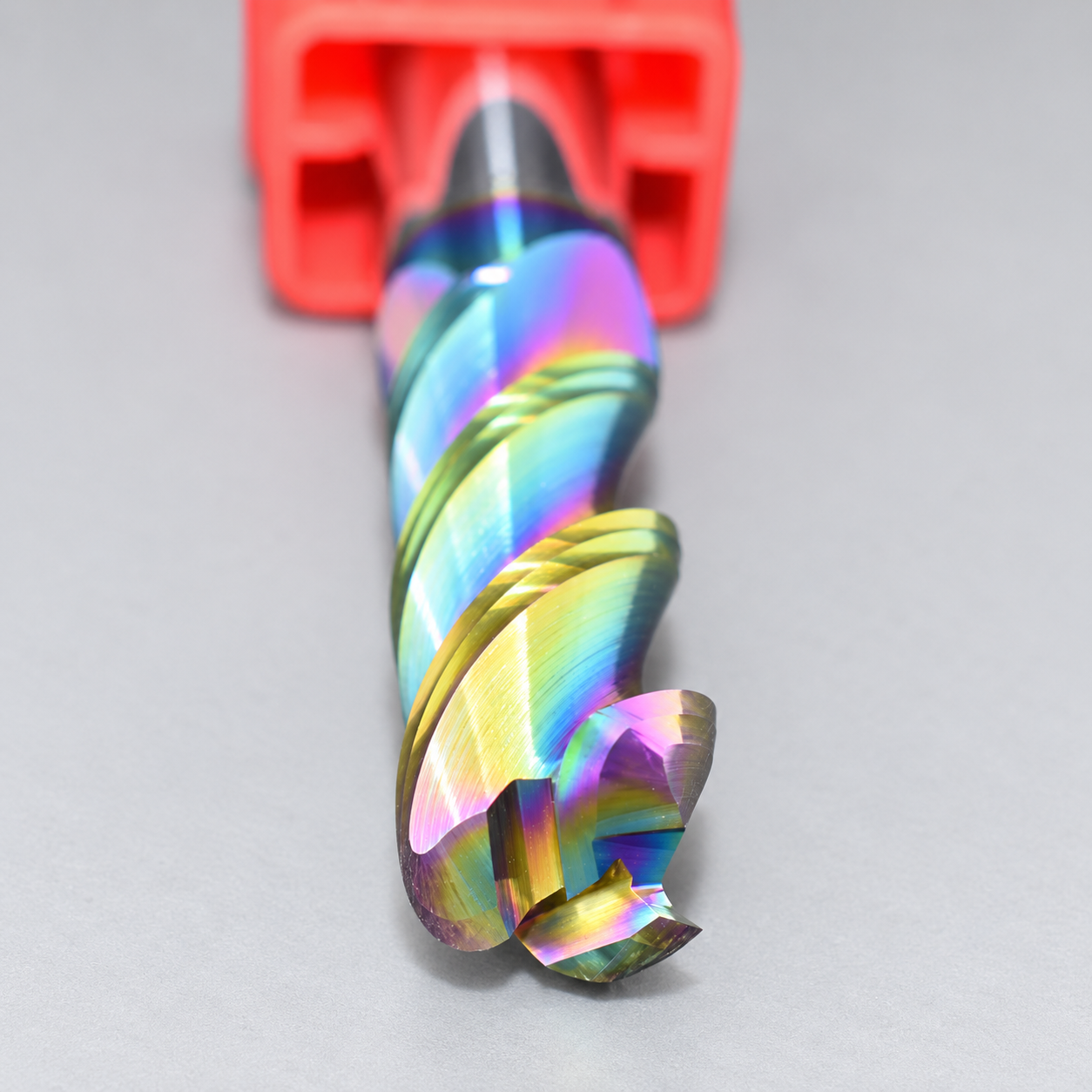
This DLC-coated solid carbide corner radius end mill is designed for smooth, efficient and precise aluminum machining.
- ◆DLC coating reduces friction and aluminum built-up edge
- ◆Corner radius design improves cutting-edge strength
- ◆Solid carbide construction for stable and precise machining
10 PCS
1–3 Days
Corner Radius End Mill
Solid Carbide
DLC Coating
Aluminum
Consistent Quality
Consistent geometry across repeat orders.
Flexible Orders
Small batches and mixed sizes available.
OEM Support
Custom marking, labels and packaging.
Standard & Custom
Standard sizes and custom configurations.
DLC-Coated Corner Radius End Mill Overview
This DLC-coated solid carbide corner radius end mill is designed for high-speed profiling, pocket finishing and semi-finishing in aluminum and aluminum alloys. The precision-ground corner radius helps reduce edge chipping, while the low-friction DLC coating limits aluminum adhesion and heat buildup for stable surface quality and repeatable tool life.
Key Product Advantages
Low-Friction DLC Coating
Helps reduce aluminum adhesion and built-up edge.
Reinforced Corner
Corner radius strengthens the cutting edge.
Stable Surface Quality
Precision-ground geometry supports consistent surface finish.
Standard & Custom Sizes
Custom diameter, radius, flute length, shank and overall length subject to drawing review.
Material, Geometry & Precision Highlights
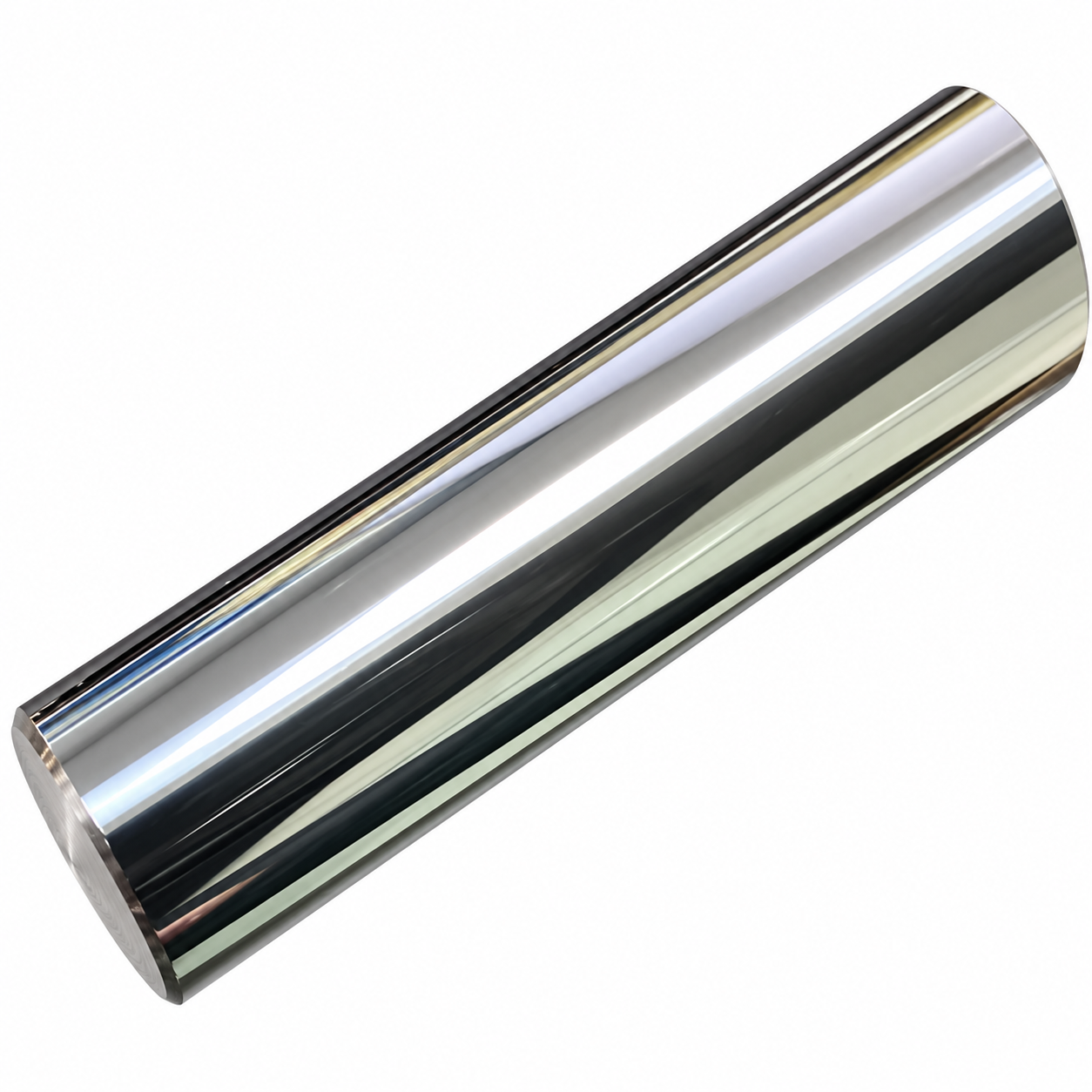
0.8 μm Fine-Grain Solid Carbide
TRS: 3600 N/mm²
Fine-grain carbide provides high bending strength and wear resistance for stable, repeatable cutting performance.
Balanced Core & Flute Geometry
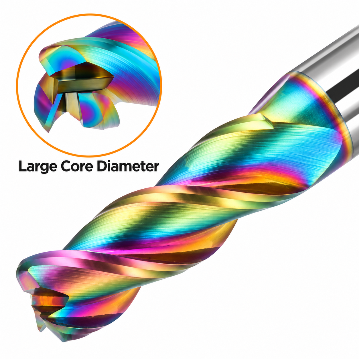
Rigidity & Chip Evacuation
Reinforced core geometry improves vibration resistance while maintaining sufficient flute space for smooth chip evacuation.
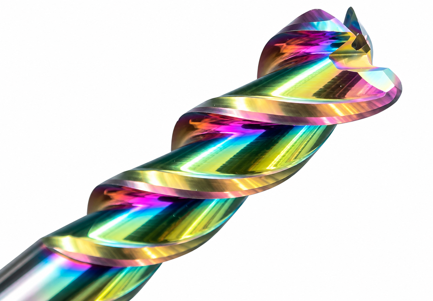
Nano-Structured Wear-Resistant Coating
Machining Capability: HRC 55–58
Wear-resistant coating helps reduce friction and tool wear while supporting stable machining of harder workpiece materials.
Precision-Ground Geometry
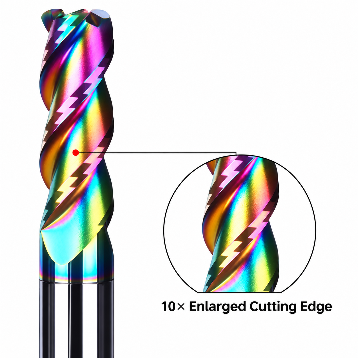
Tool Tolerance: 0.005 mm
5-axis CNC grinding supports consistent cutting-edge geometry and repeatable dimensional accuracy.
10× Cutting-Edge Detail
Chamfered Shank Design
Stable Clamping & Easy Setup
Chamfered shank entry supports smoother holder installation, reliable positioning and repeatable clamping.
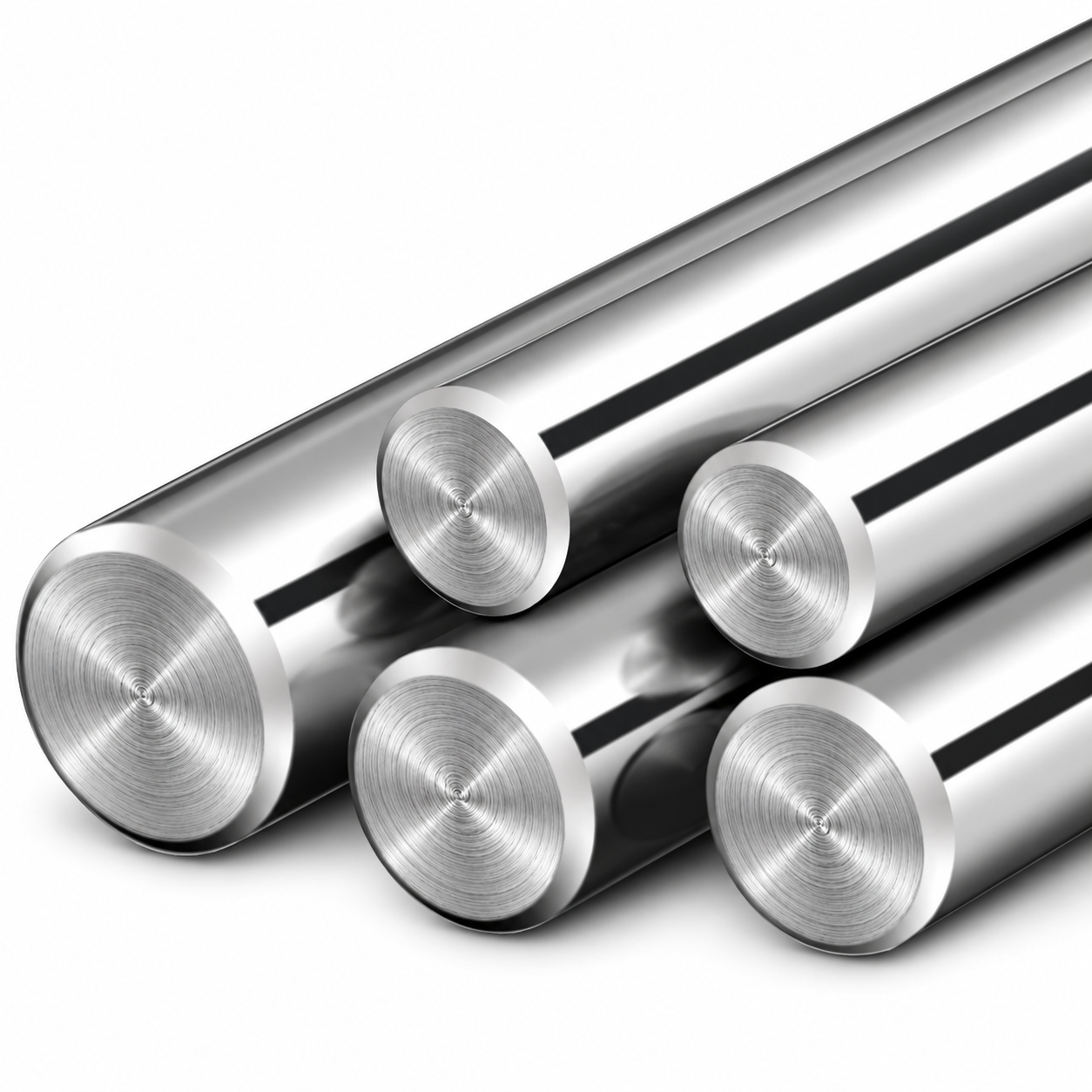
Applications & Materials
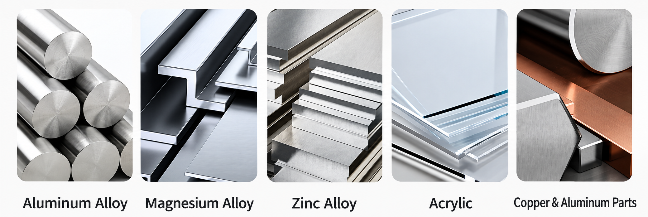
Recommended for side profiling, contour milling, pocket finishing, edge finishing and selected semi-finishing operations in rigid CNC machining conditions.
Product Details

DLC Corner Radius End Mill Specifications
Technical configuration, available size combinations and starting cutting references for the DLC-coated solid carbide corner radius end mill for aluminum.
| PARAMETER | SPECIFICATION |
|---|---|
| Tool Material | Premium Solid Carbide |
| Tool Type | Corner Radius End Mill |
| Coating | DLC (Diamond-Like Carbon) |
| Reference DC Range | Ø1–Ø12 mm in the listed size matrix |
| Reference OAL | 50 / 60 / 75 mm according to size |
| Primary Materials | Aluminum / aluminum alloys / copper / brass / selected non-ferrous materials |
| Machine Compatibility | CNC machining centers / milling machines |
| Custom Supply | Drawing-based diameter, radius, flute length, shank diameter, overall length and geometry |
Dimensions & Reference Sizes
All dimensions are in millimeters. The source did not reliably identify the flute count, so it must be confirmed for the selected model.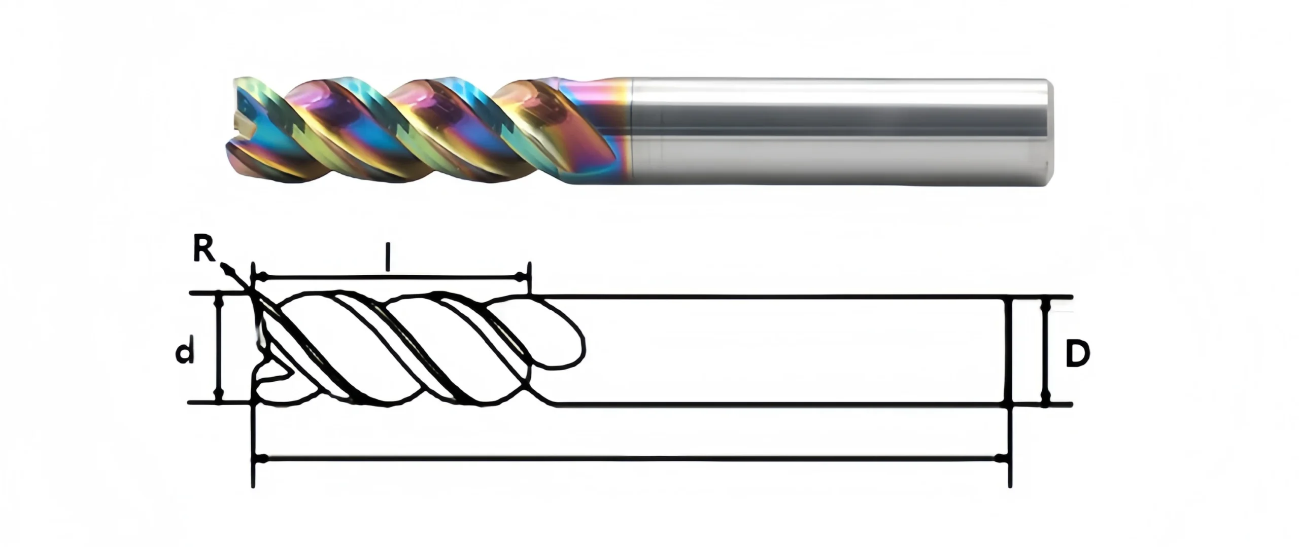
| SPECIFICATION | DC | R | DCON | OAL |
|---|---|---|---|---|
| Ø1×R0.2×D4×50L | 1 | 0.2 | 4 | 50 |
| Ø1.5×R0.2×D4×50L | 1.5 | 0.2 | 4 | 50 |
| Ø2×R0.2 / R0.3 / R0.5×D4×50L | 2 | 0.2 / 0.3 / 0.5 | 4 | 50 |
| Ø2.5×R0.2 / R0.5×D4×50L | 2.5 | 0.2 / 0.5 | 4 | 50 |
| Ø3×R0.2 / R0.3 / R0.5 / R1×D3 or D4×50L | 3 | 0.2 / 0.3 / 0.5 / 1 | 3 / 4 | 50 |
| Ø4×R0.2 / R0.3 / R0.5 / R1×D4×50L | 4 | 0.2 / 0.3 / 0.5 / 1 | 4 | 50 |
| Ø5×R0.5 / R1×D6×50L | 5 | 0.5 / 1 | 6 | 50 |
| Ø6×R0.2 / R0.3 / R0.5 / R1×D6×50L | 6 | 0.2 / 0.3 / 0.5 / 1 | 6 | 50 |
| Ø6×R0.2 / R0.5 / R1×D8×60L | 6 | 0.2 / 0.5 / 1 | 8 | 60 |
| Ø8×R1.5 / R2×D8×60L | 8 | 1.5 / 2 | 8 | 60 |
| Ø10×R0.5 / R1 / R1.5 / R2 / R3×D10×75L | 10 | 0.5 / 1 / 1.5 / 2 / 3 | 10 | 75 |
| Ø12×R0.5 / R1 / R2 / R3×D12×75L | 12 | 0.5 / 1 / 2 / 3 | 12 | 75 |
Starting Cutting Data for Aluminum
| WORKPIECE | VC (m/min) | FZ (mm/tooth) | AP | AE |
|---|---|---|---|---|
| Aluminum & Aluminum Alloys | 300–600 | 0.05–0.12 | 0.3–1.0 × DC | 0.05–0.30 × DC |
DLC Corner Radius End Mill Customization
Custom dimensions, corner radius and DLC coating for aluminum and non-ferrous machining.
| PARAMETER | MANUFACTURING CAPABILITIES |
|---|---|
| Cutting Diameter | Ø1–Ø12 mm reference; custom sizes per approved drawing |
| Corner Radius | Standard or custom radius |
| Flute Configuration | Flute count and geometry confirmed by model |
| Flute & Overall Length | Standard, extended or drawing-defined lengths |
| Shank Configuration | Cylindrical shank; custom dimensions per drawing |
| DLC Coating | Low-friction coating for non-ferrous machining |
OEM & Private Label Services
Custom marking, labels and protective packaging for your brand.

Technical Workflow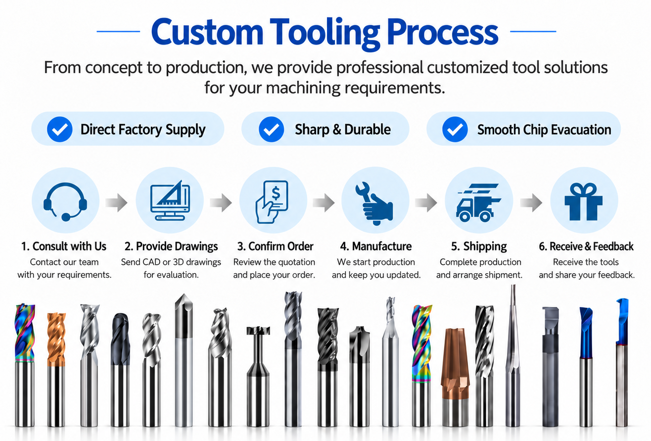
Quality, Inspection & Delivery
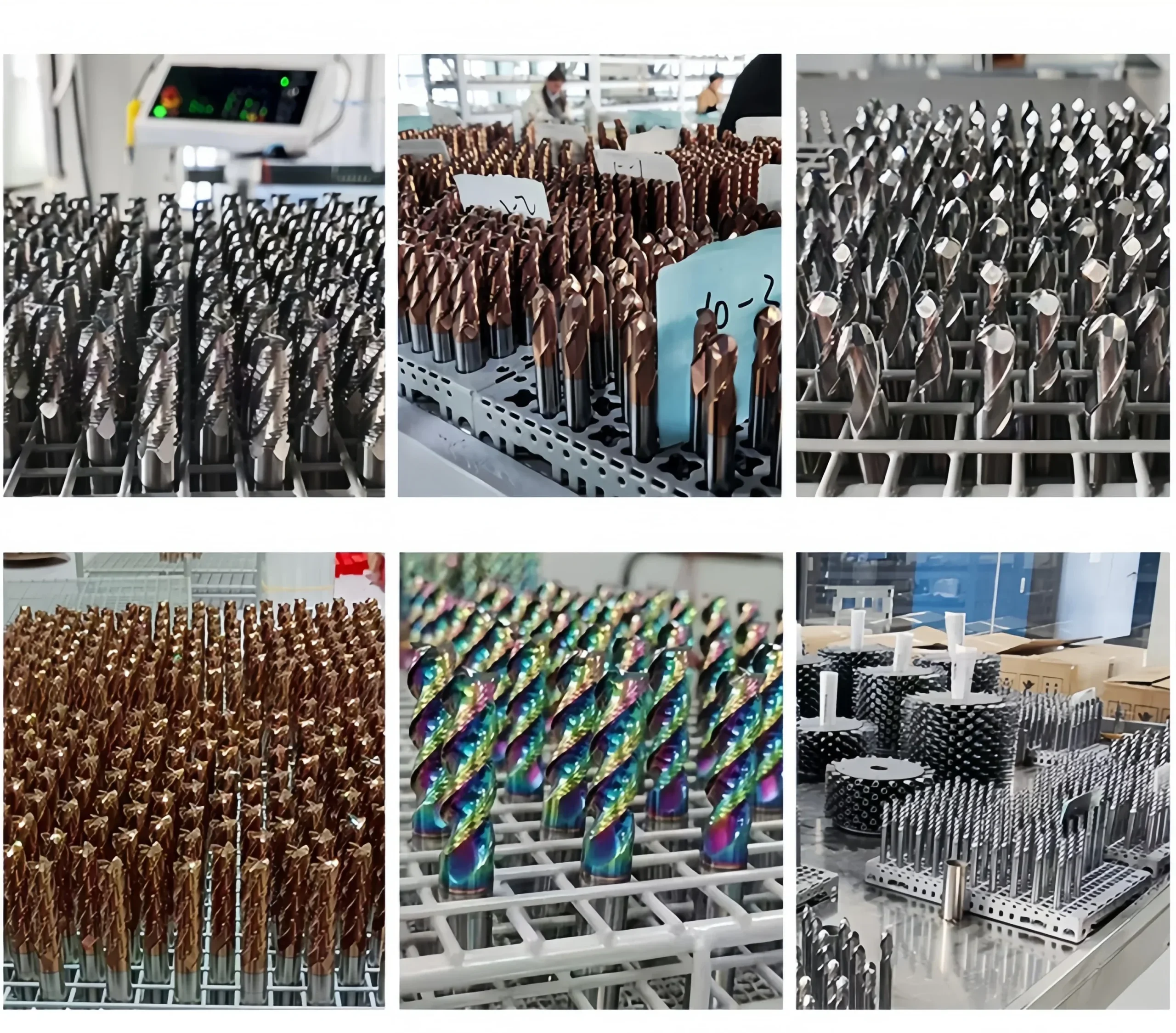
Our solid carbide square end mills are verified through material checks, precision grinding, dimensional inspection and final quality control before packing.

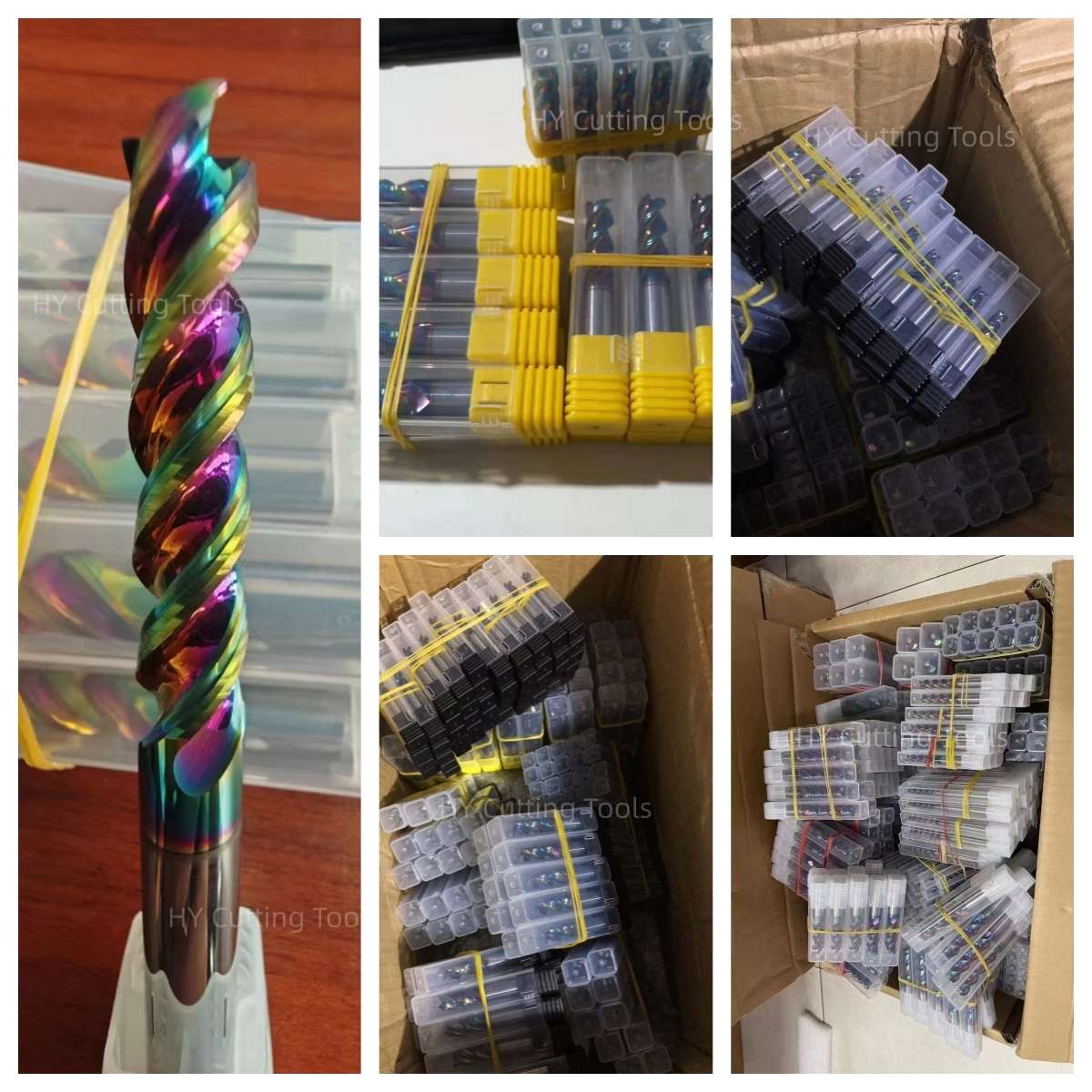
Protective Packaging Process
Protected packaging helps prevent edge damage and ensures clear product identification.

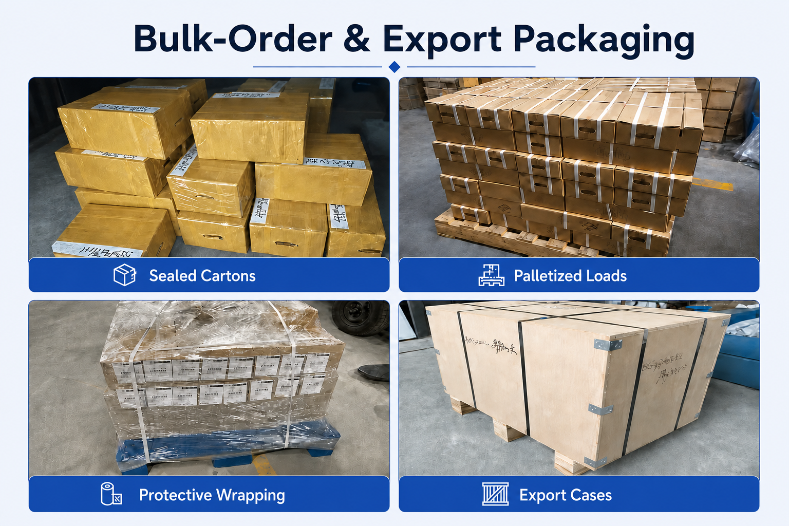
Bulk-Order & Export Packaging
Bulk shipments can be arranged with reinforced cartons, protective wrapping, palletized loading or export cases according to order quantity, shipment weight and agreed transportation requirements.

FAQ & Downloads
Review common questions and access the latest end mill catalog and cutting-data guide.
Product & Application FAQs
Selection and application guidance for aluminum and non-ferrous material machining.
What materials is this DLC-coated corner radius end mill designed to machine?
It is primarily designed for aluminum and aluminum alloys. Suitable configurations can also be reviewed for copper, brass and other compatible non-ferrous materials. Please provide the exact alloy and silicon content when requesting an application review.
What are the benefits of the DLC coating?
The low-friction diamond-like carbon coating helps reduce aluminum adhesion, built-up edge and heat generation. It can also improve wear resistance and support more consistent surface quality during continuous CNC production.
What operations are suitable for the corner-radius design?
The corner-radius geometry is suitable for side profiling, contour milling, pocket finishing, edge finishing and selected semi-finishing operations. It produces a controlled component fillet while providing greater corner strength than a sharp-corner square end mill.
How should I select the corner radius?
Select a corner radius equal to or smaller than the required component fillet. The final R value should also be reviewed according to the cutting diameter, machining allowance, required corner strength and finished-part geometry.
Is this DLC-coated end mill suitable for steel?
This configuration is primarily intended for aluminum and compatible non-ferrous materials. For carbon steel, alloy steel, mold steel or hardened steel, select a steel-specific carbide substrate, cutting-edge preparation and heat-resistant coating such as AlTiN or TiSiN.
What coolant method is recommended?
Air blast, minimum-quantity lubrication or a suitable coolant can be used according to the aluminum grade and machining operation. Reliable chip evacuation is important to prevent chip recutting and maintain the benefits of the DLC coating.
Ordering & Customization FAQs
For distributors, tooling brands and custom-order customers.
What reference sizes are available?
The reference series includes selected cutting diameters from Ø1 to Ø12 mm with multiple corner-radius, shank-diameter and overall-length combinations. Final availability and flute configuration should be confirmed for the selected model.
Can custom dimensions and geometry be manufactured?
Yes. Cutting diameter, corner radius, flute count, flute length, neck geometry, shank diameter, overall length and cutting-edge preparation can be reviewed according to the drawing and machining application.
Can I order samples before placing a bulk order?
Yes. Sample orders and custom-size trials can be reviewed according to the required dimensions, DLC coating specification and quantity. Please contact us to confirm sample availability, production cost and delivery charges.
What is the lead time?
In-stock standard configurations can normally be dispatched within 1–3 working days. Production time for custom dimensions, special corner radii, DLC coating, laser marking or private-label packaging is confirmed after the specification and order quantity have been reviewed.
Are OEM marking and private-label packaging available?
Yes. Customer logos, tool codes, cutting dimensions, coating identification and batch numbers can be laser marked according to the available shank area. Custom labels, protective tubes and private-label packaging can also be supplied.
What information is required for an accurate quotation?
Please provide the aluminum or non-ferrous material grade, silicon content, cutting diameter, corner radius, flute count, flute length, shank diameter, overall length, machining operation, axial depth ap, radial engagement ae, tolerance requirements and order quantity. A drawing is recommended for custom projects.
Technical Downloads
Access current product-range information and starting cutting references for solid carbide end mill selection.
Solid Carbide End Mills Catalog
End mill families, coating options, material applications and reference sizes.
End Mill Speeds & Feeds Guide
Starting cutting speeds, chip loads, engagement guidance and adjustment notes.
Need Sizes, Pricing or Custom Options?
Send us the required tool type, sizes, quantities, workpiece material and any OEM or custom requirements. We will confirm suitable specifications, availability, lead time and quotation details.
Drawings, size lists and reference photos are welcome.