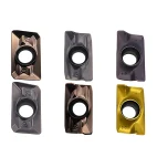
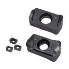
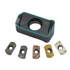
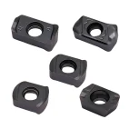
LNMU/ENMU/BLMP Double-Sided High-Feed Carbide Milling Inserts
LNMU, ENMU and BLMP double-sided carbide inserts are developed for high-feed milling with shallow depths of cut and increased table feed. Their strong cutting-edge geometry supports productive roughing, pocketing and face milling. Multiple grades and chipbreakers are available for steel, stainless steel, cast iron and selected alloy materials.
Consistent Quality
Consistent geometry across repeat orders.
Flexible Orders
Small batches and mixed sizes available.
OEM Support
Custom marking, labels and packaging.
Standard & Custom
Standard sizes and custom configurations.
◆Product Overview
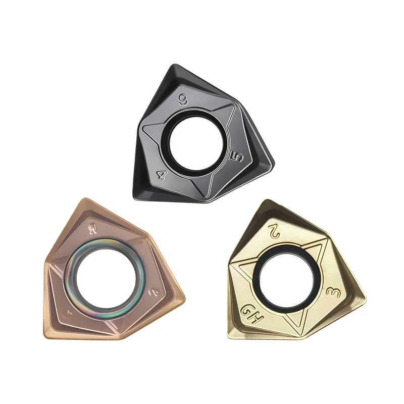
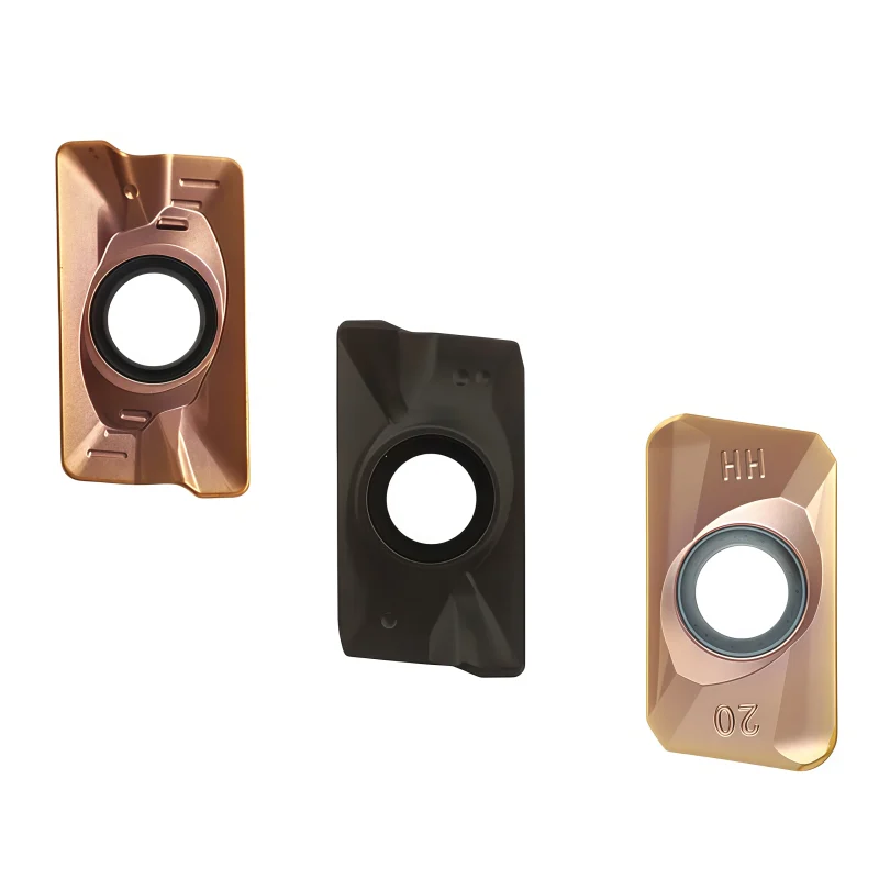
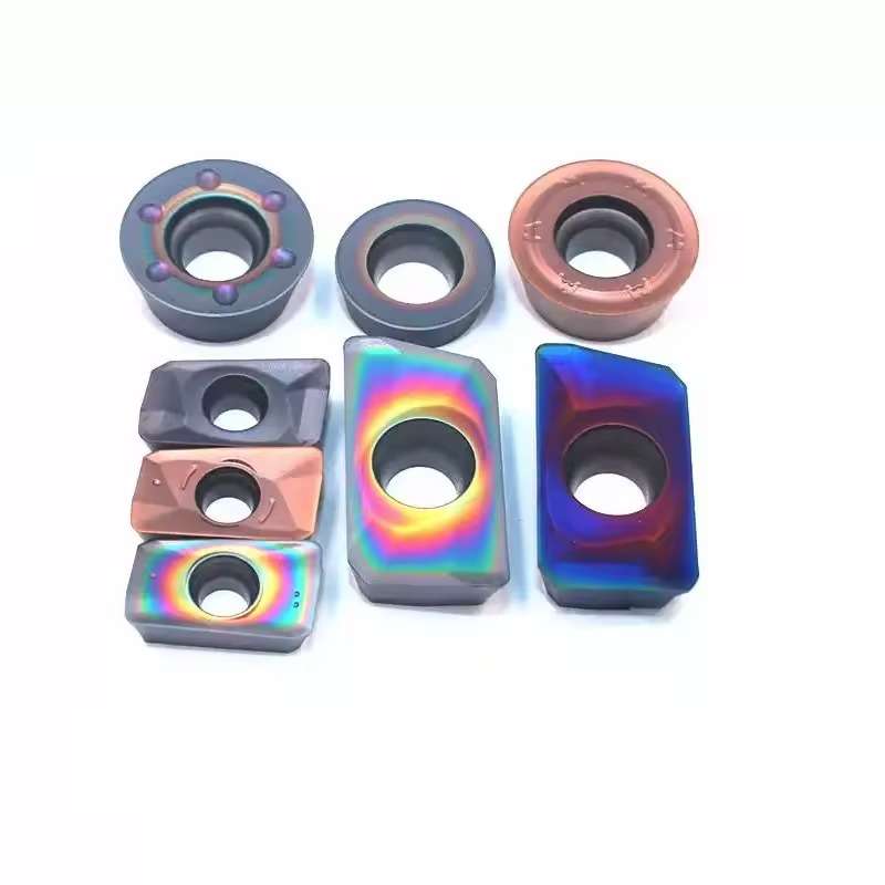
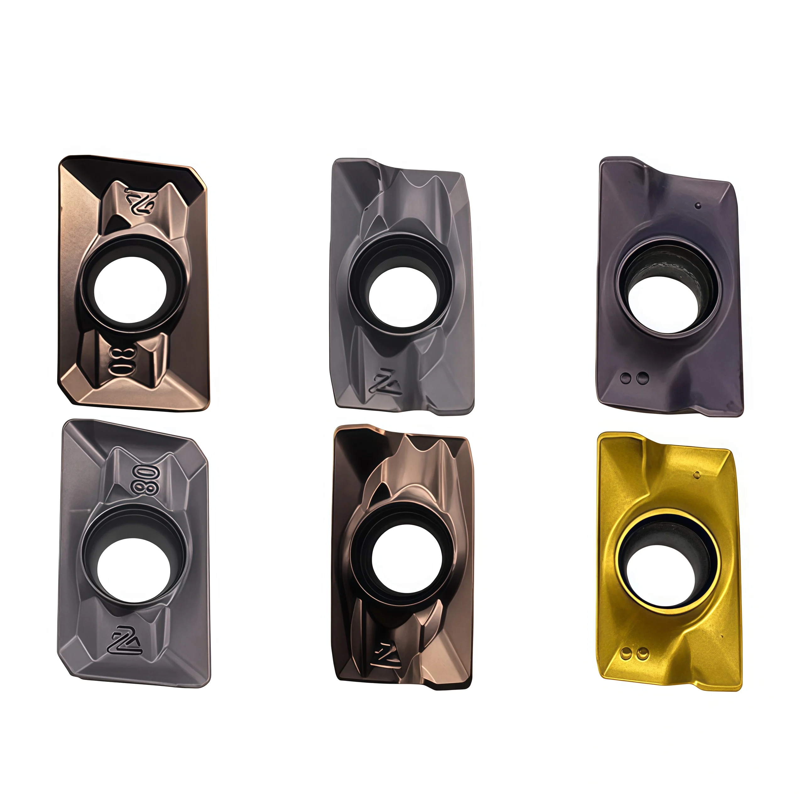
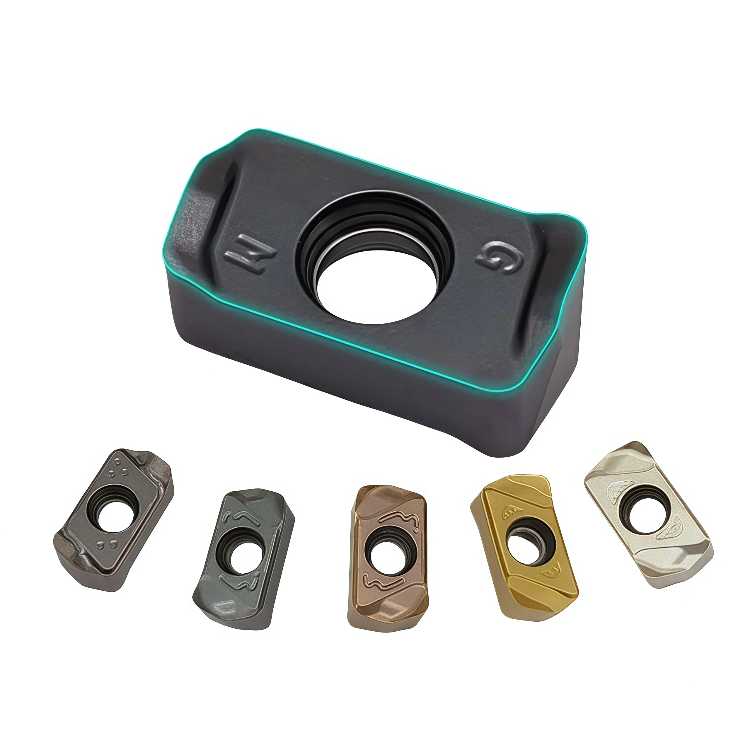
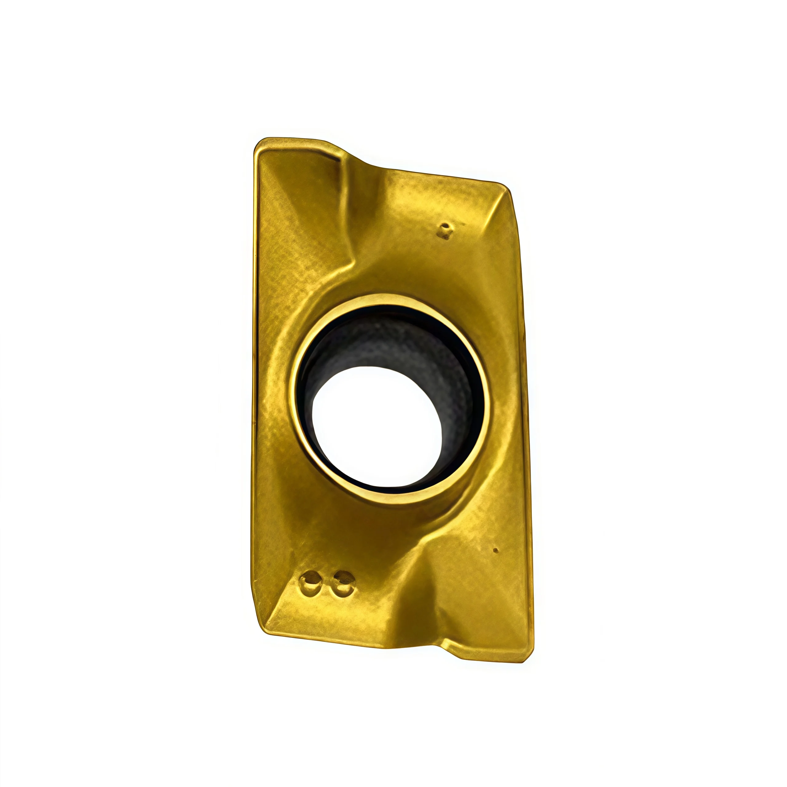
LNMU0303, ENMU0603ER and BLMP0904R are three insert families offered on this page for double-sided, indexable high-feed milling. They are intended for productive roughing with a compatible high-feed cutter, where a small entering angle permits a relatively high feed per tooth at a controlled axial depth of cut. Each family requires its own matching cutter pocket and application data.
Choose the complete insert code by workpiece material, cutter body, geometry, carbide grade and coating. The supplied description mentions micro-grain carbide and PVD coating, but does not identify a grade or coating for every model. The number of usable edges and the allowable tool path must also be confirmed for the selected insert and cutter.
◆Key Configuration
Three Insert Families
LNMU0303, ENMU0603ER and BLMP0904R are distinct designations. Match the complete insert model to the approved cutter-body code and pocket drawing.
High-Feed Geometry
The selected insert and cutter control chip thinning, allowable axial depth and effective cutting diameter. Apply feed recommendations for the actual cutter assembly.
Grade & Edge Count
Confirm the specified carbide grade, coating, chipbreaker and usable edges per insert. These values cannot be established from the three family names alone.
◆Applications & Selection
High-feed face milling and cavity roughing are application starting points. Steel (ISO P), stainless steel (ISO M), cast iron (ISO K), tool steel or harder materials require the corresponding supplier-approved grade and cutting data. Ramping, helical entry, plunging and full-width slotting depend on the particular cutter body’s published limits.
◆Product Images
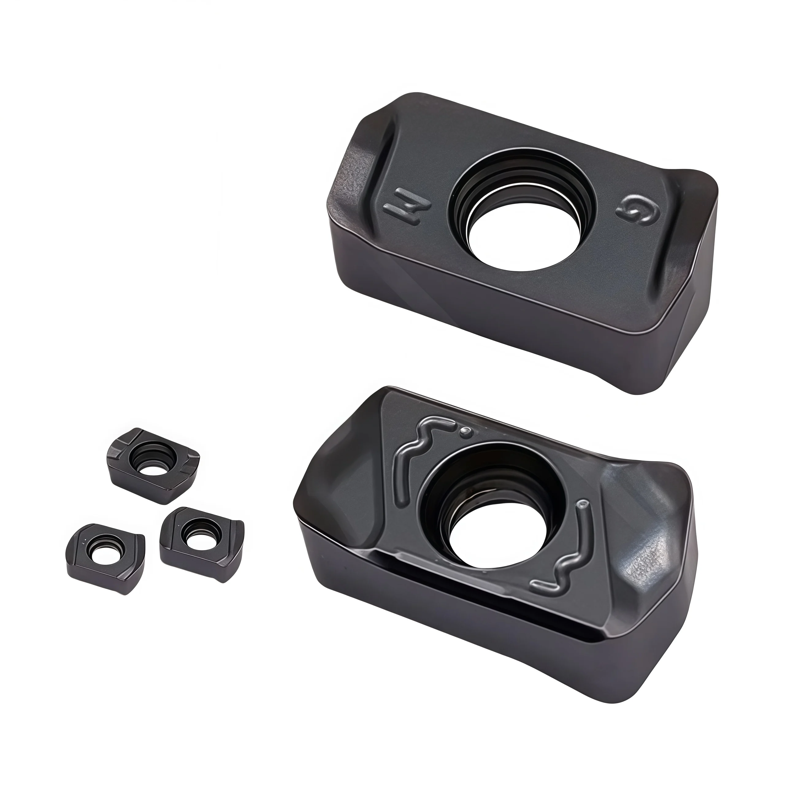
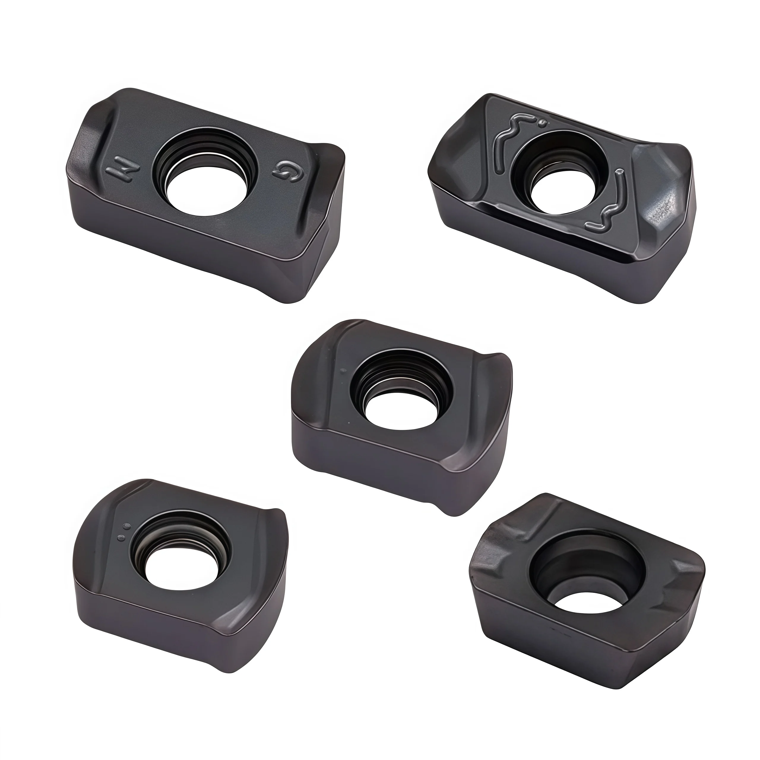
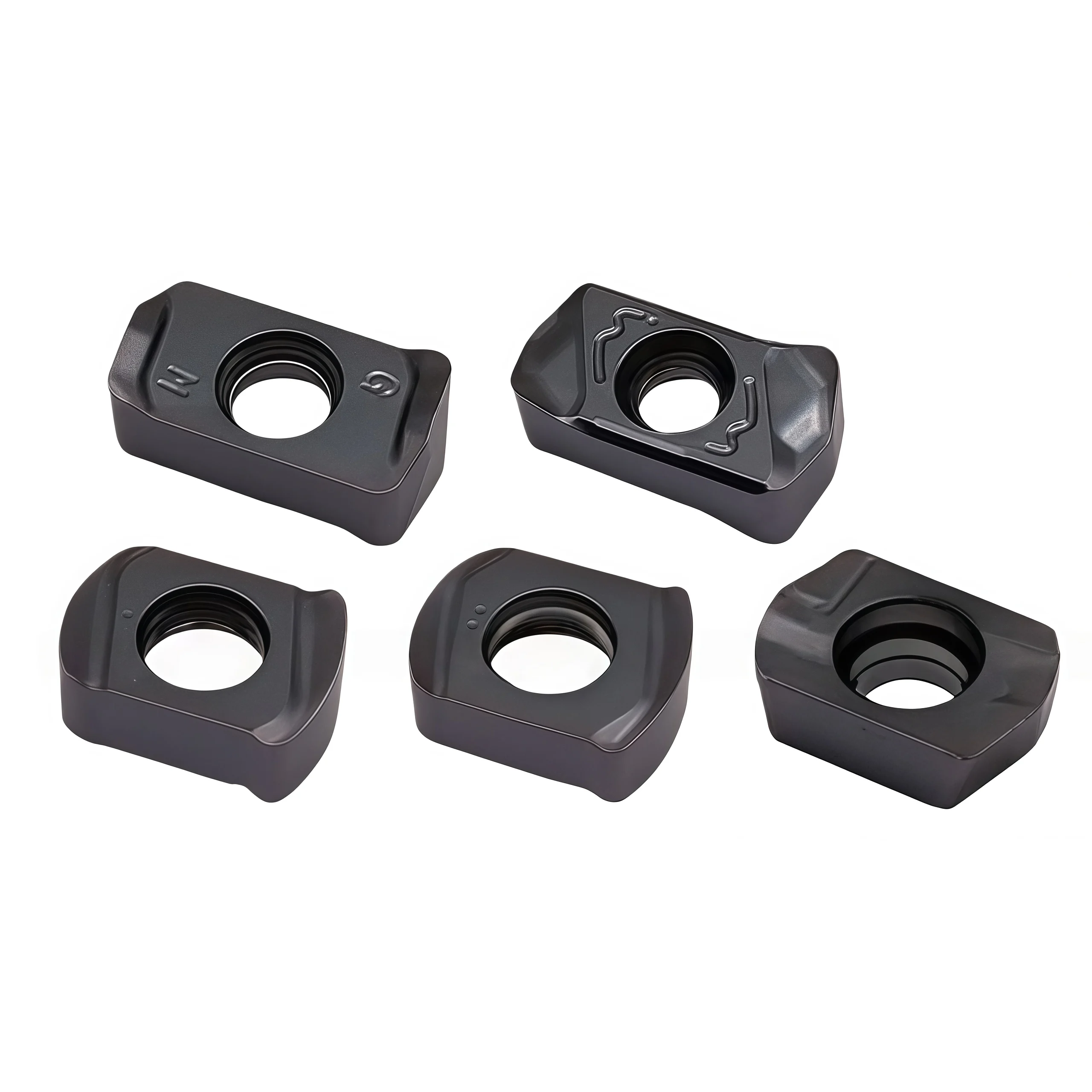
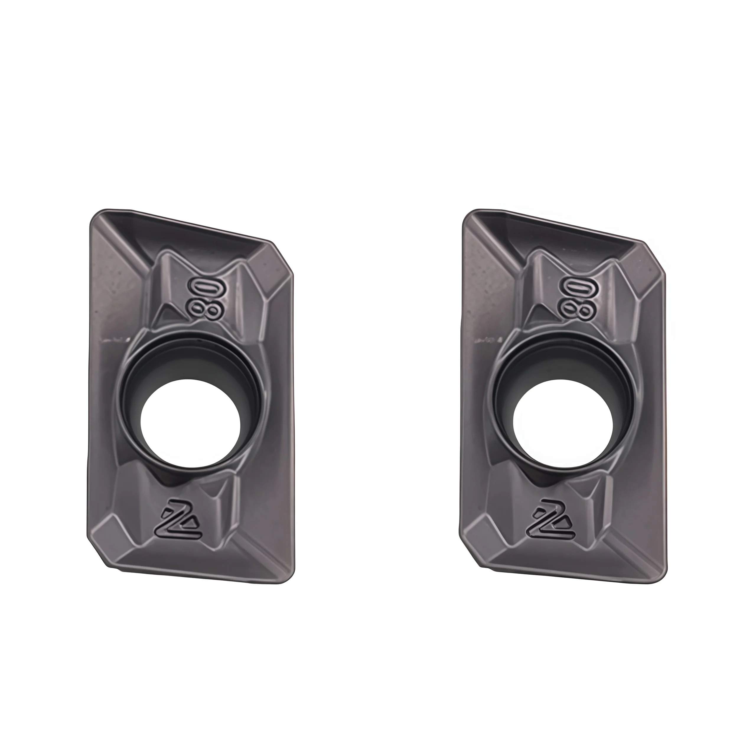
◆Machining Video
The video demonstrates machining. Confirm the insert code, cutter, workpiece and cutting parameters separately for your application.
◆Specifications & Series
This page groups three named high-feed milling insert families. The supplied product copy does not include a dimensioned manufacturer drawing, exact carbide grades or coating codes. The model numbers below identify inquiry options; obtain the matching insert and cutter-body drawings before treating a dimension or fit as approved.
| Series Named | Use on This Page | Details Required for Selection |
|---|---|---|
| LNMU0303 | Double-sided high-feed milling series | Complete suffix, measured dimensions, edge count, grade and matching cutter body. |
| ENMU0603ER | Double-sided high-feed milling series | Complete suffix, measured dimensions, edge count, grade and matching cutter body. |
| BLMP0904R | High-feed milling series named in the supplied description | Confirm double-sided configuration, usable edges, drawing, grade and matching cutter body. |
◆Configuration to Confirm
| Item | Specification Check |
|---|---|
| Insert material | Carbide; request the specific substrate grade and application range for each ordered model. |
| Coating & geometry | Confirm coating system, chipbreaker, edge preparation and all usable cutting edges by full item code. |
| Size & clamping | Compare the insert drawing with cutter pocket, screw, seat and specified tightening torque. |
| Workpiece | Specify steel (ISO P), stainless steel (ISO M), cast iron (ISO K) or another material by exact grade and hardness; verify grade-specific suitability. |
| Operation | Face or cavity roughing as applicable. Check axial depth, radial engagement, ramp angle, helical entry, plunge and slotting limits with the chosen cutter. |
◆How to Select the Insert
◆Starting Cutting Data
High-feed milling generally combines a relatively shallow axial depth (ap) with a feed per tooth (fz) appropriate to the selected cutter geometry. Obtain the manufacturer's recommended cutting speed (Vc), fz, ap, radial width (ae) and entry limits for the complete insert grade and cutter. The supplied product copy does not establish numerical ranges.
◆Related Guide & Ordering
Use our Carbide Insert Types Guide for a general family overview. Send the full insert and cutter-body codes to request the corresponding drawing, grade options and application data.
◆Carbide Insert Customization & OEM
Specify the insert around the machining operation, workpiece and holder. We can review standard replacements, application-specific geometry and private-label requirements using your insert designation, drawing or sample. Available grades, coatings, dimensions and order quantities are confirmed for each requested series.
Geometry & Chip Control
Review chipbreaker, rake, cutting-edge preparation, nose radius and corner design for the operation and workpiece. Confirm holder compatibility before approving a modified geometry.
Substrate & Coating
Select an available carbide grade and coating for the workpiece material, cutting conditions and desired balance of wear resistance and edge toughness.
Dimensions & OEM
Review insert size, thickness, locating and clamping features, tolerances, laser marking and private-label packaging against the approved specification.
◆Customization Options
Use the fields below when sending an inquiry. The exact options depend on the insert family and are confirmed in the quotation or approved drawing.
| Specification | Details to Confirm |
|---|---|
| Insert Type | Turning, milling, threading, grooving or drilling insert; send the designation or drawing. |
| Size & Fit | Shape, size, thickness, inscribed circle or edge length, hole or clamping form, and holder model. |
| Cutting Geometry | Chipbreaker, nose or corner radius, edge preparation, cutting direction and application-specific profile. |
| Grade & Coating | Workpiece group and grade, carbide substrate, coating system and wet or dry cutting conditions. |
| Tolerance & Inspection | Critical dimensions, profile requirements, inspection method and any required report. |
| OEM Presentation | Insert or box marking, label content, packaging format and quantity per pack. |
◆How to Request a Custom Insert

Send your insert requirements through our contact form or review our OEM and private-label service.
◆Carbide Insert Quality Control

Insert quality depends on the approved grade, geometry, coating and dimensional specification. We review the requirements at order confirmation and align the inspection scope with the insert series and any customer drawing. Share critical dimensions or documentation needs before production so they can be included in the agreed inspection plan.
01 · Incoming Material
Confirm the specified carbide grade or material documentation against the order requirements.
02 · In-Process Checks
Review dimensions and cutting-edge features during production against the approved specification.
03 · Final Inspection
Check the agreed dimensions, appearance, edge condition, coating identification and marking as applicable.
04 · Packing Review
Verify the item code, quantity, labels and protective packing against the approved order.
◆Inspection & Documentation
Inspection points and acceptance criteria should be agreed for the ordered series. For custom inserts, the approved drawing takes priority over a generic catalogue description.
| Check Area | What to Confirm |
|---|---|
| Dimensions & Fit | Insert size, thickness, corner radius, clamping features and any drawing tolerances. |
| Cutting Geometry | Chipbreaker, edge preparation, usable corners and profile where applicable. |
| Grade & Coating | Approved grade and coating designation; any requested verification method. |
| Appearance & Packing | Visible edge damage, marking, item code, count and packing format. |
| Requested Records | Inspection report, material or coating documentation, sample approval or batch identification when agreed. |
◆Order & Delivery
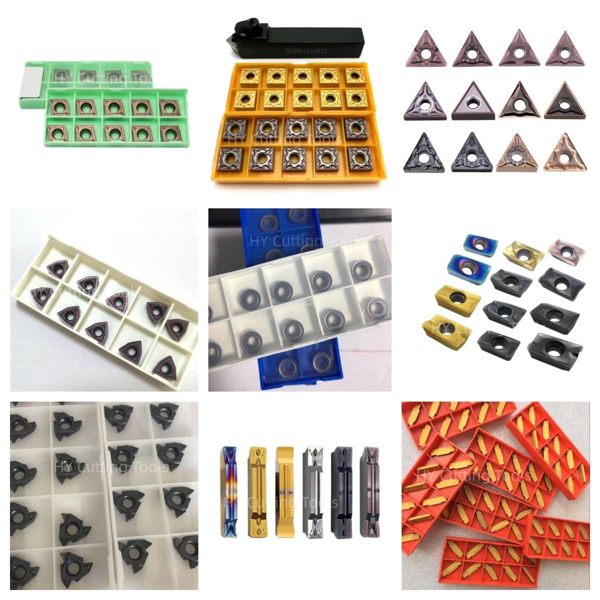

Share a line-by-line list of insert codes and quantities for a mixed-size quotation. Stock status, minimum quantity, sample requirements and production lead time are confirmed for each grade, coating and configuration.
Send your item list and quality requirements through our contact form for specification, availability and delivery confirmation.
◆Product FAQs
What is high-feed milling?
A compatible high-feed cutter uses its entering-angle and insert geometry to produce a relatively thin chip at a shallow axial depth. This can permit a higher feed per tooth than conventional milling under the cutter maker's specified conditions. The allowable depth and feed depend on the complete cutter and insert combination.
Are LNMU0303, ENMU0603ER and BLMP0904R interchangeable?
No interchangeable fit is established by these family names. Match each complete code to the cutter's approved insert list and compare pocket, seat, screw, dimensions and cutting geometry before selecting a replacement.
How many cutting edges does each double-sided insert have?
A double-sided design can offer usable edges on both faces, but the count varies with the insert shape and edge design. Request the drawing and indexing instructions for the selected full model. The supplied description does not verify a common edge count for all three families.
Can these inserts mill steel, stainless steel and cast iron?
Suitability depends on the exact carbide grade, coating and geometry. Provide the workpiece grade and hardness, operation, coolant and expected cut type so an ISO P, M or K application can be checked against the offered variant.
Can I ramp, plunge or slot with this range?
These capabilities differ by cutter body and insert. Check the published maximum ramp angle, helical entry dimensions, allowable axial depth and full-width slotting guidance for your exact tool before programming the path.
Where are the exact dimensions and cutting parameters?
The supplied page content contains model names but no verified dimension drawing or grade-specific speed and feed table. Request the selected insert drawing and cutter-specific Vc, fz, ap and ae recommendations using the full insert and cutter-body codes.
◆Ordering & OEM FAQs
What information should I send for a replacement?
Send the original insert's full code and grade, box-label and both-face photos, cutter-body code, workpiece material, cutting conditions, current wear issue and required quantity. An approved sample cut should confirm fit and performance.
Can the three insert families be ordered together?
Provide a line-by-line list with the full model, grade and quantity for each family. Availability, pack count, minimum order quantity and lead time are confirmed by item.
Are coated grades and custom configurations available?
Share the target workpiece, cutter details and requested substrate, coating or edge geometry. Feasibility and the exact approved specification are confirmed in the quotation or drawing.
Can I request OEM marking or packaging?
Send the proposed marking, label artwork, pack format, model list and quantity. Confirm the sample, approved design and delivery terms before production.
◆Guides & Technical References
Use our CNC Insert Selection Guide and Carbide Insert Types Guide for initial insert selection.
For a drawing or quotation, send the complete insert and cutter-body codes with your workpiece and operation.
Need Sizes, Pricing or Custom Options?
Send us the required tool type, sizes, quantities, workpiece material and any OEM or custom requirements. We will confirm suitable specifications, availability, lead time and quotation details.
Drawings, size lists and reference photos are welcome.