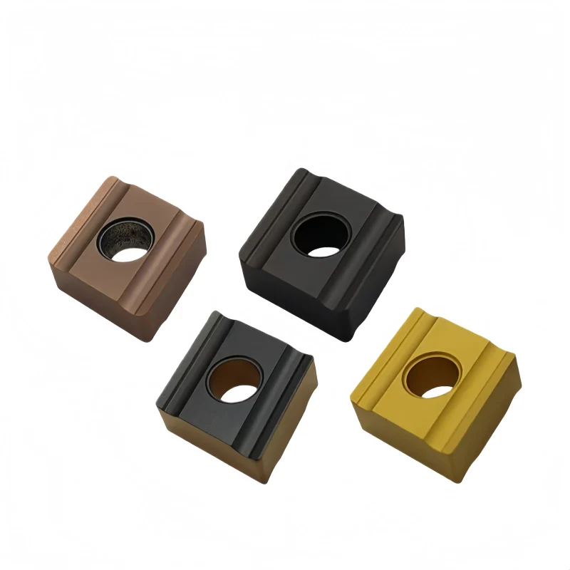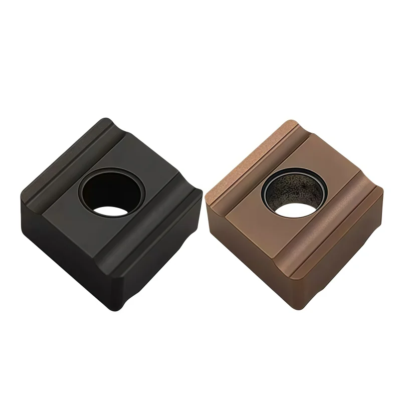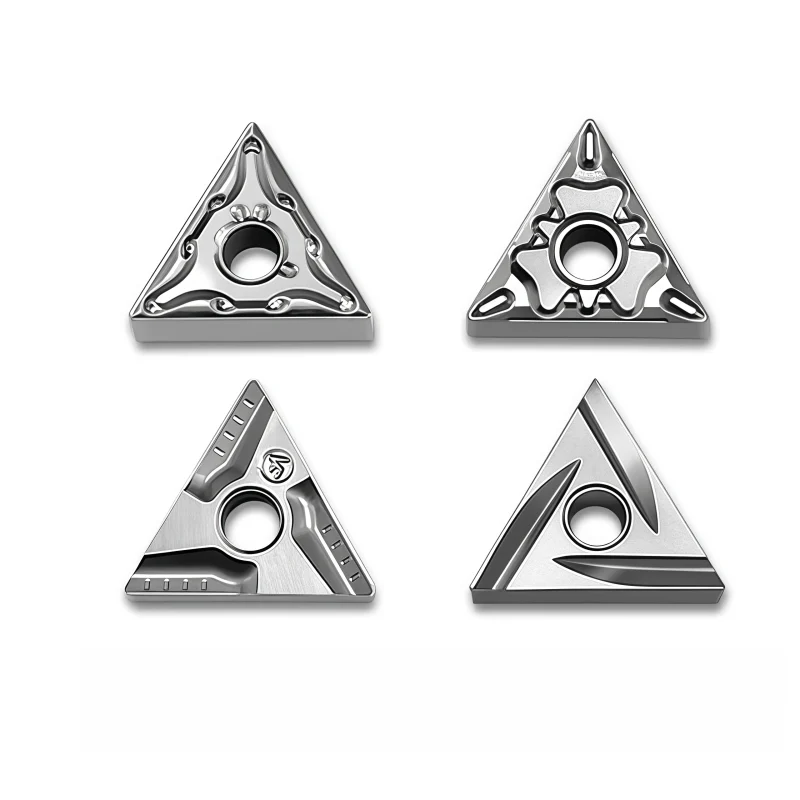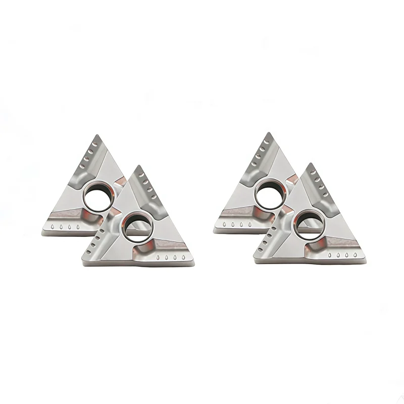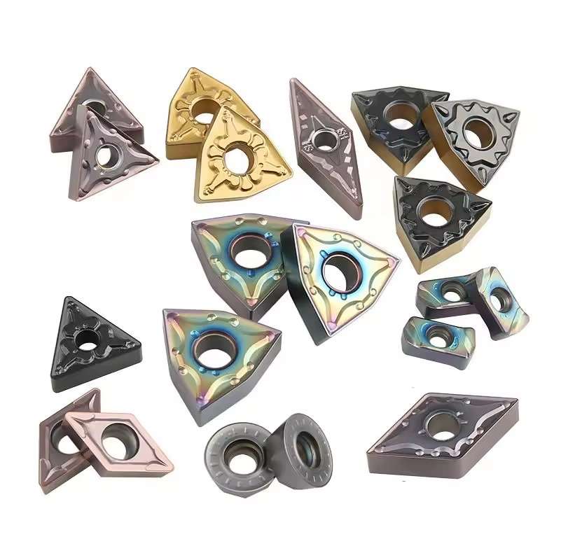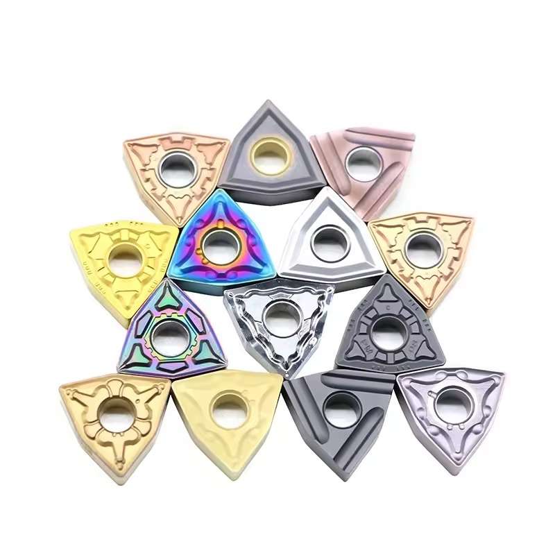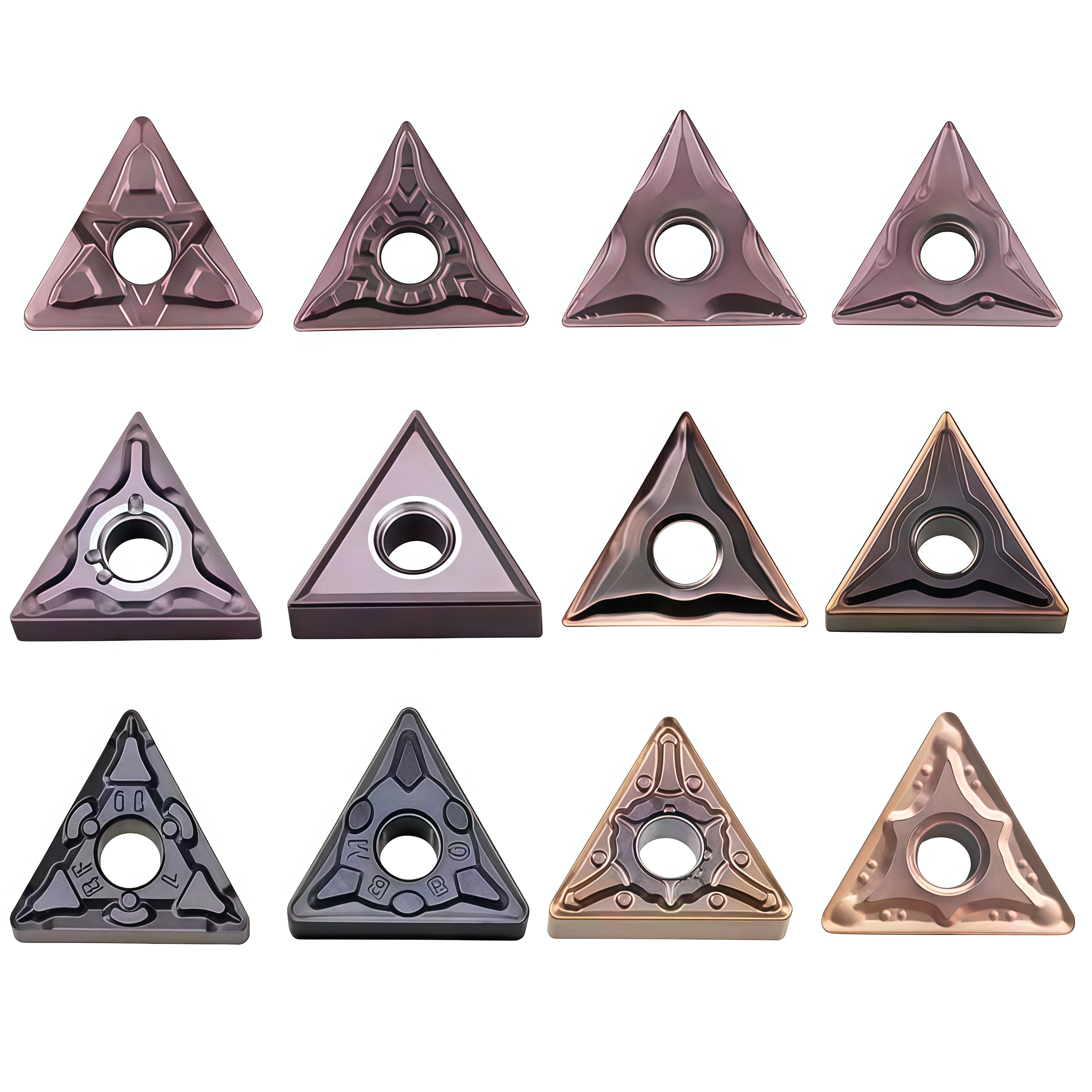
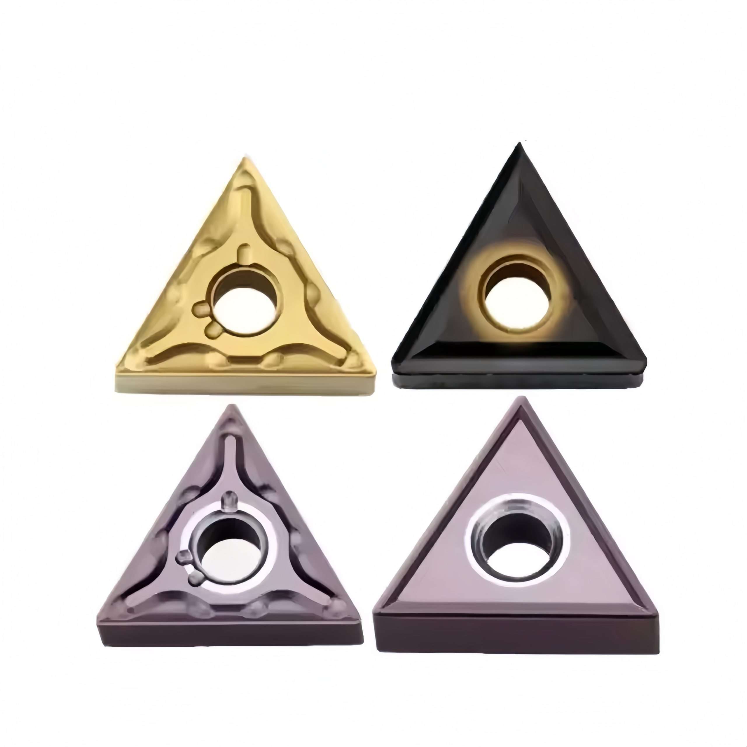
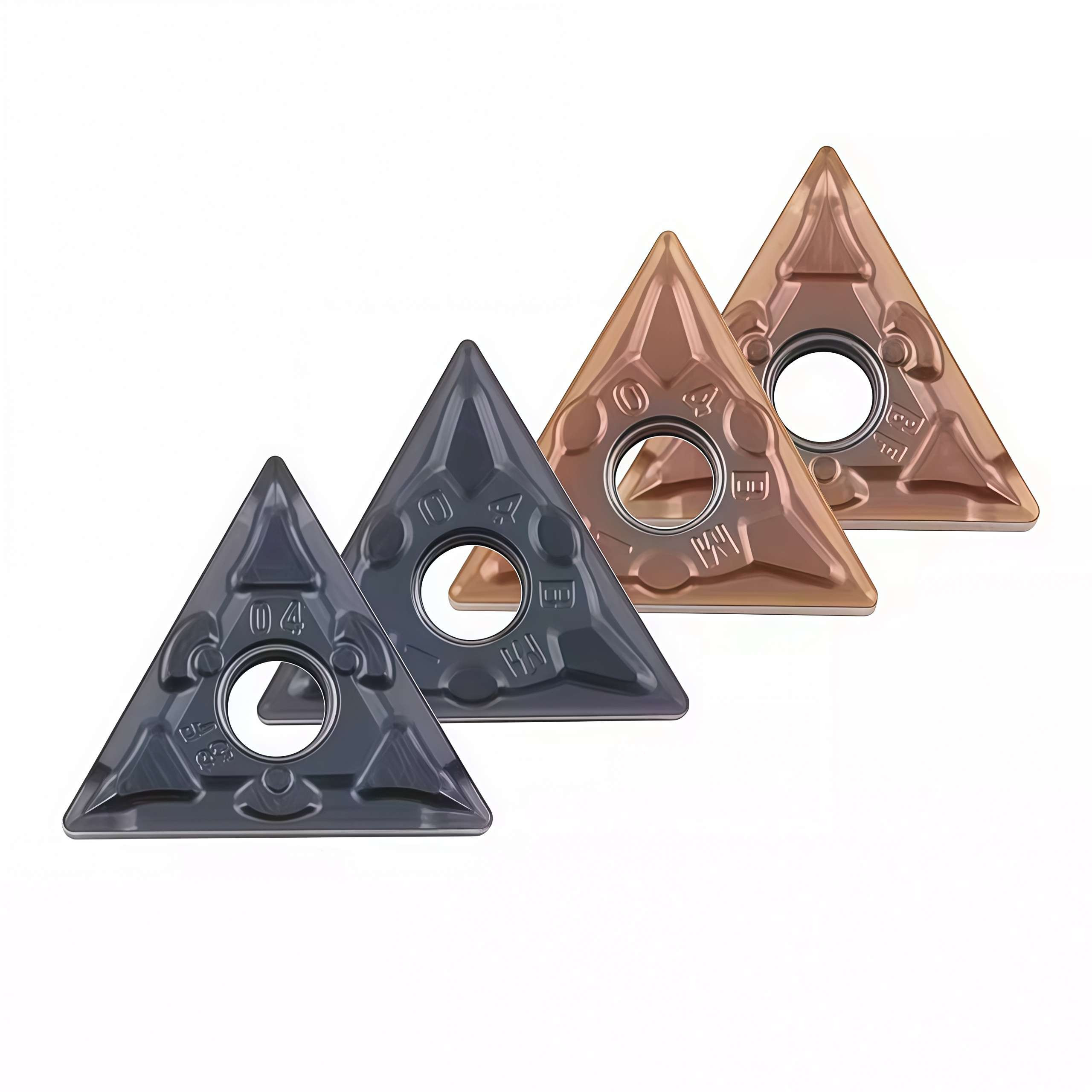
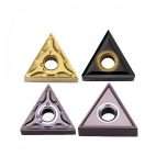
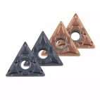
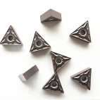
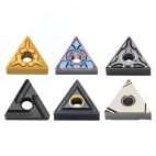
TNMG 160404/160408/160412 Coated Carbide Turning Inserts for Steel
TNMG 160404, 160408 and 160412 coated carbide turning inserts provide a practical corner-radius range for steel turning, facing and profiling. The double-sided triangular geometry offers six usable edges, while coated grades and chipbreakers support finishing, medium machining and roughing. This coverage helps distributors build a balanced steel-turning inventory.
Consistent Quality
Consistent geometry across repeat orders.
Đơn hàng linh hoạt
Small batches and mixed sizes available.
OEM Support
Custom marking, labels and packaging.
Tiêu chuẩn & Theo yêu cầu
Standard sizes and custom configurations.
◆Product Overview
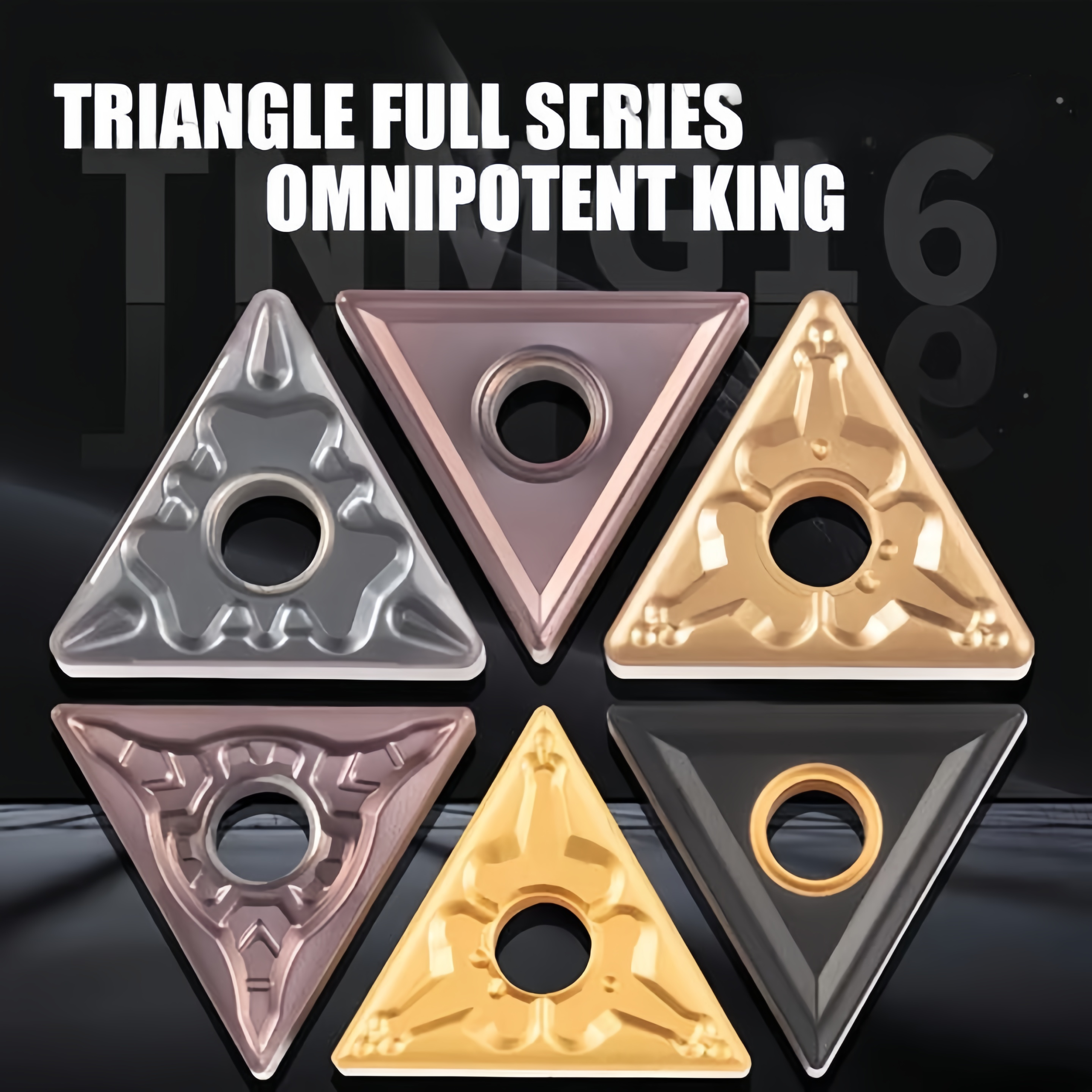
The TNMG series carbide turning inserts are designed for CNC external turning, facing and profiling operations. Their triangular negative geometry provides a strong cutting edge and multiple usable cutting edges, supporting economical machining across finishing, medium-turning and selected roughing conditions.
Multiple carbide grades, PVD/CVD coatings and chipbreaker geometries are available for steel, stainless steel and cast iron applications. Actual material suitability and recommended cutting parameters depend on the complete insert code, grade, chipbreaker and machining conditions.
| Product Name | TNMG carbide turning inserts | Insert Material | Tungsten carbide |
|---|---|---|---|
| Insert Geometry | Triangular, negative clearance | Operations | Turning / Facing / Profiling |
| Workpiece Materials | Steel / Stainless steel / Cast iron | Material Suitability | Grade and chipbreaker dependent |
| Grade Options | TBG2110 / TBG2025 / TBC2015 / TBD2025 and other options | Coating & Color | PVD/CVD options; appearance varies by grade |
| Reference Speed | 160–220 m/min under selected conditions | Standard Pack | 10 pieces per plastic box |
| Supply Options | Standard / Mixed models / Repeat supply | Branding Options | Neutral / Private label / Customer SKU labels |
The listed cutting speed is a general reference only. Confirm the starting parameters according to the selected grade, material hardness, feed, cutting depth, rigidity and coolant condition.
◆Model, Grade and Chipbreaker Reference
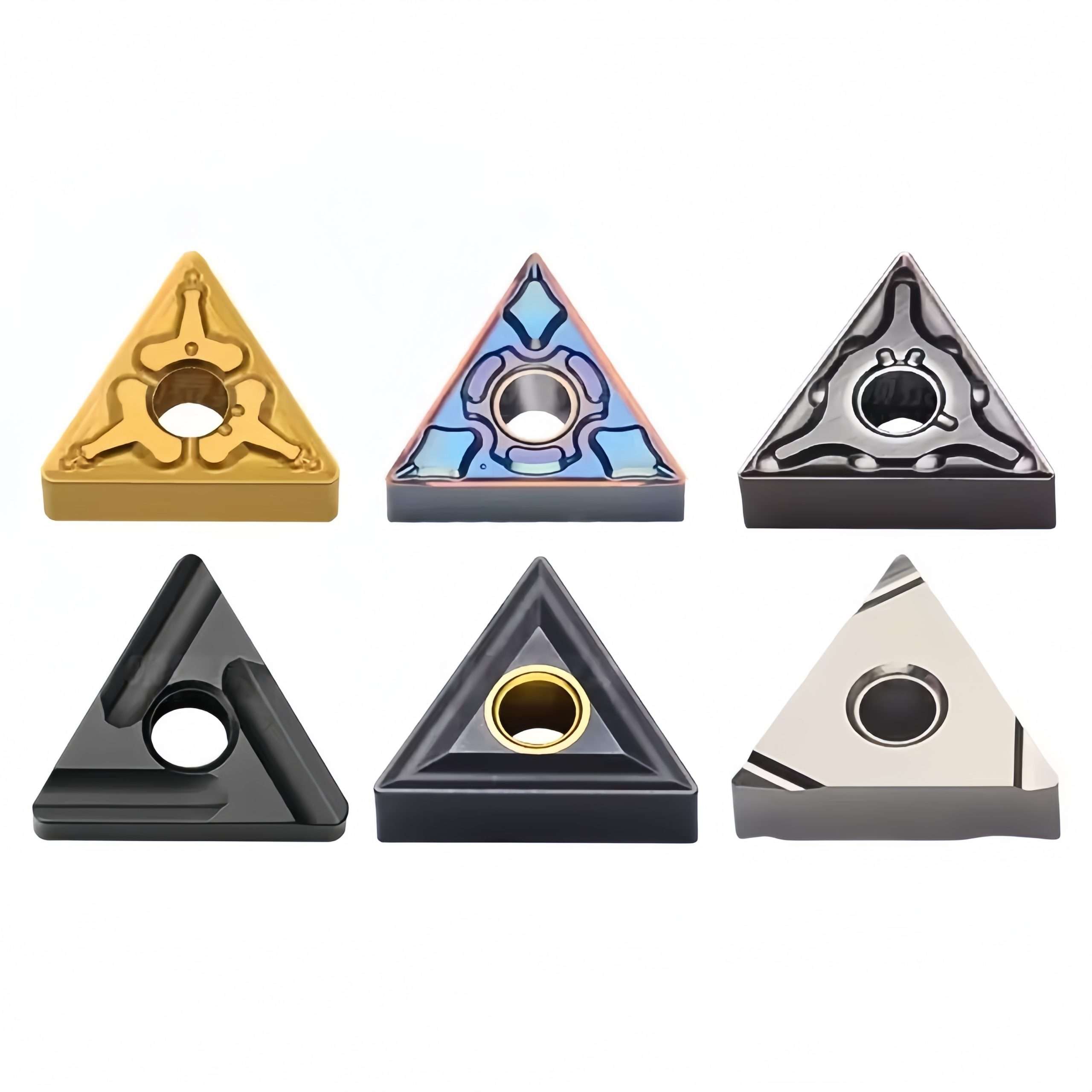
The following catalogue images show model dimensions, workpiece-material groups, chipbreaker choices and grade recommendations. Use the complete insert code when requesting model matching.
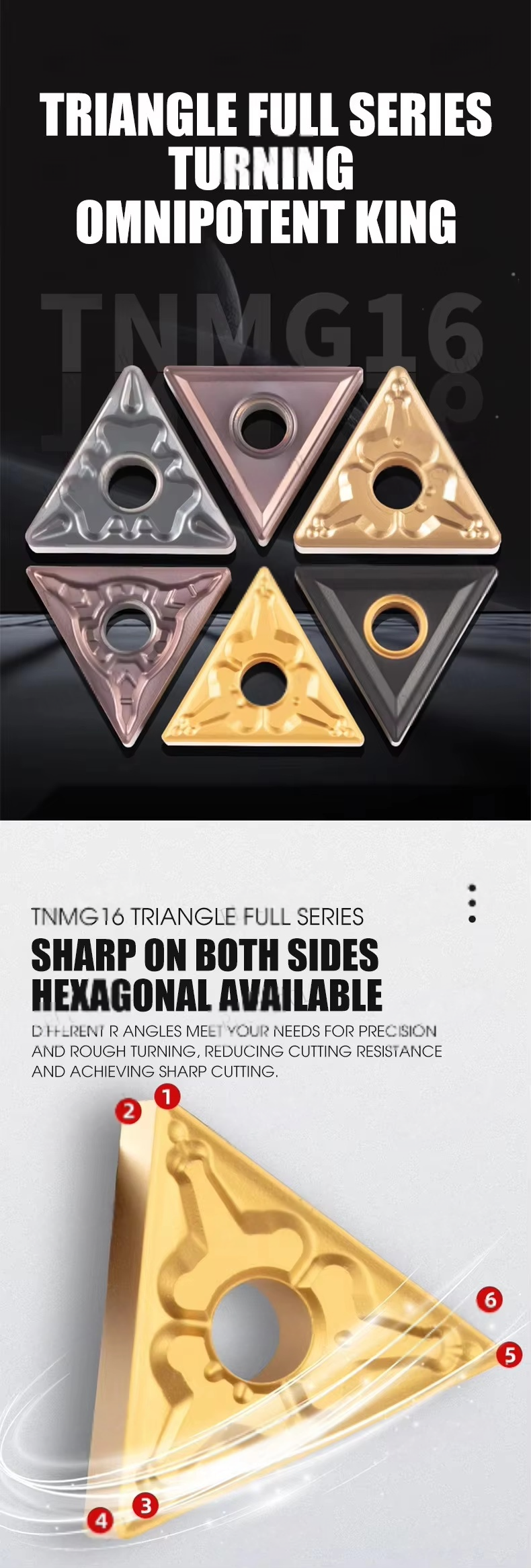
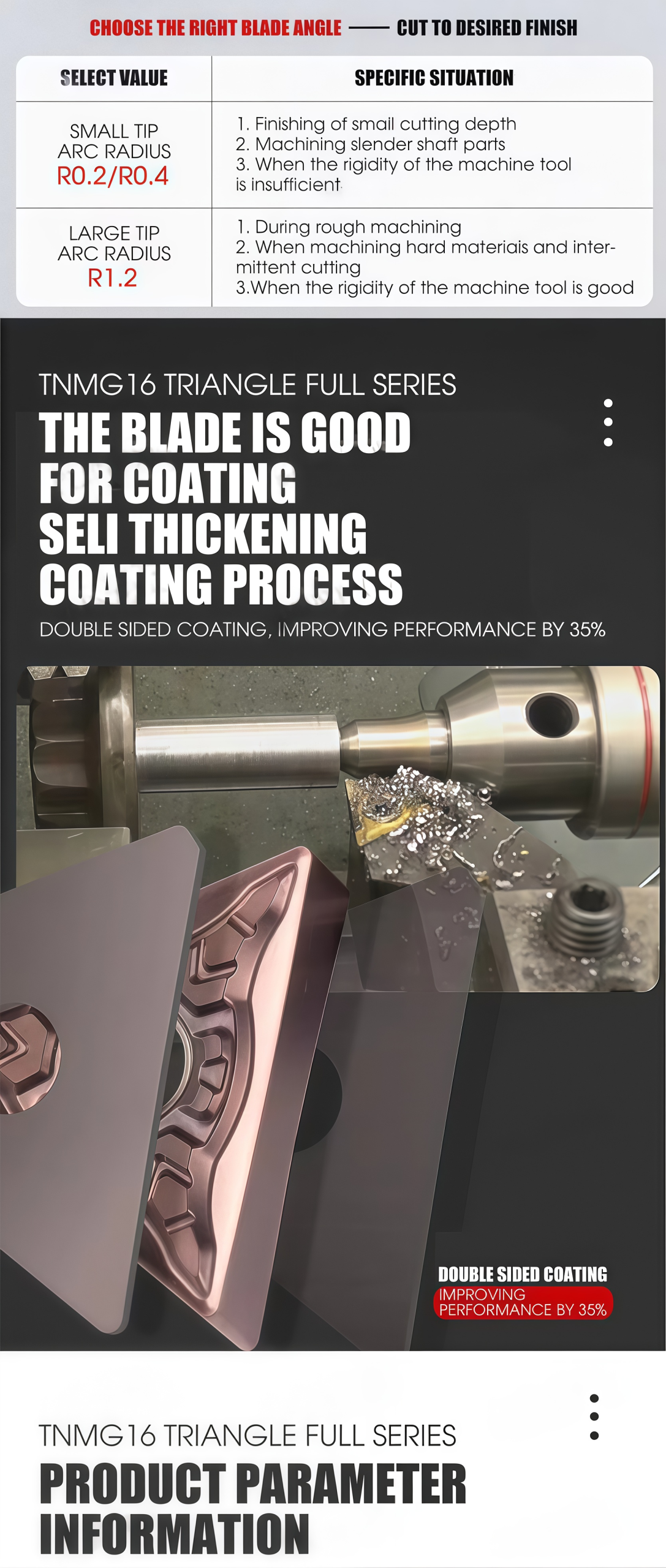
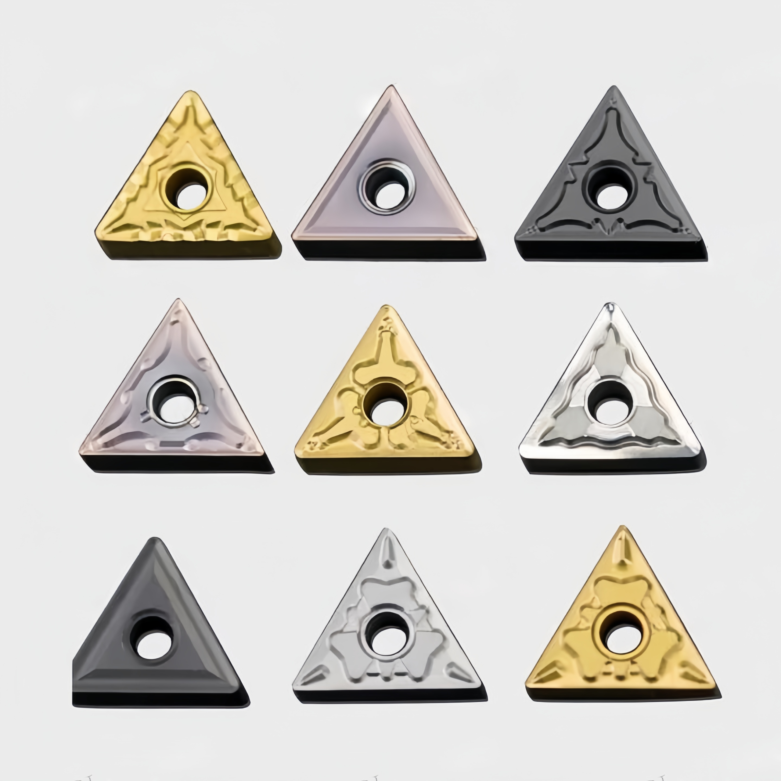
The same TNMG size may be available in several carbide grades and chipbreakers. Selection should be based on the workpiece material, hardness, cutting speed, cutting depth, feed, machine rigidity and coolant condition.
Coating color is not a reliable method of grade identification. Always confirm the printed insert code or original package label.
Finishing geometry for smaller cutting depth and controlled chip formation
Medium geometry for general production turning
Stronger geometry for higher load and rougher conditions
Trial cutting recommended before volume replacement
◆Product and Cutting-Edge Details
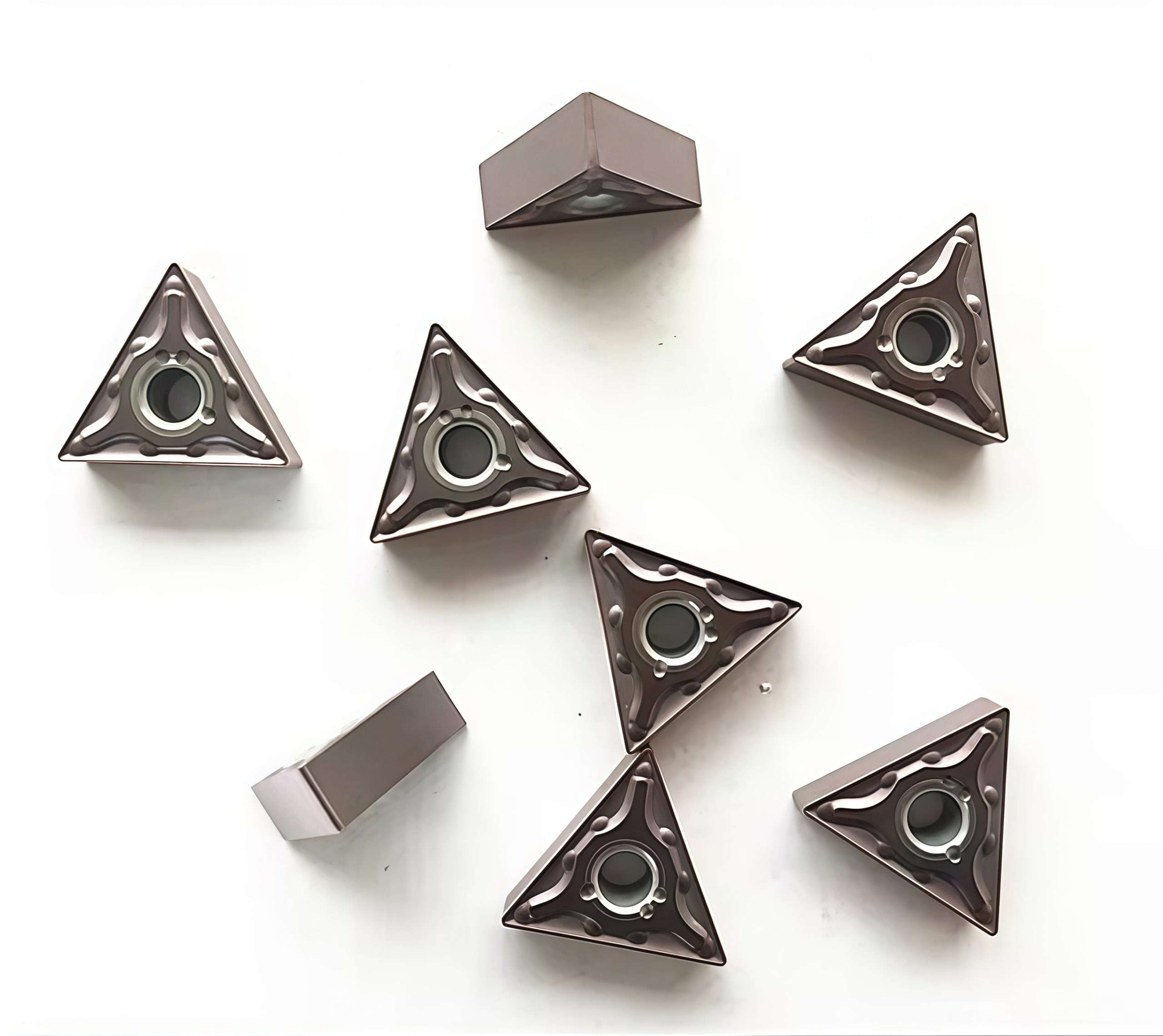
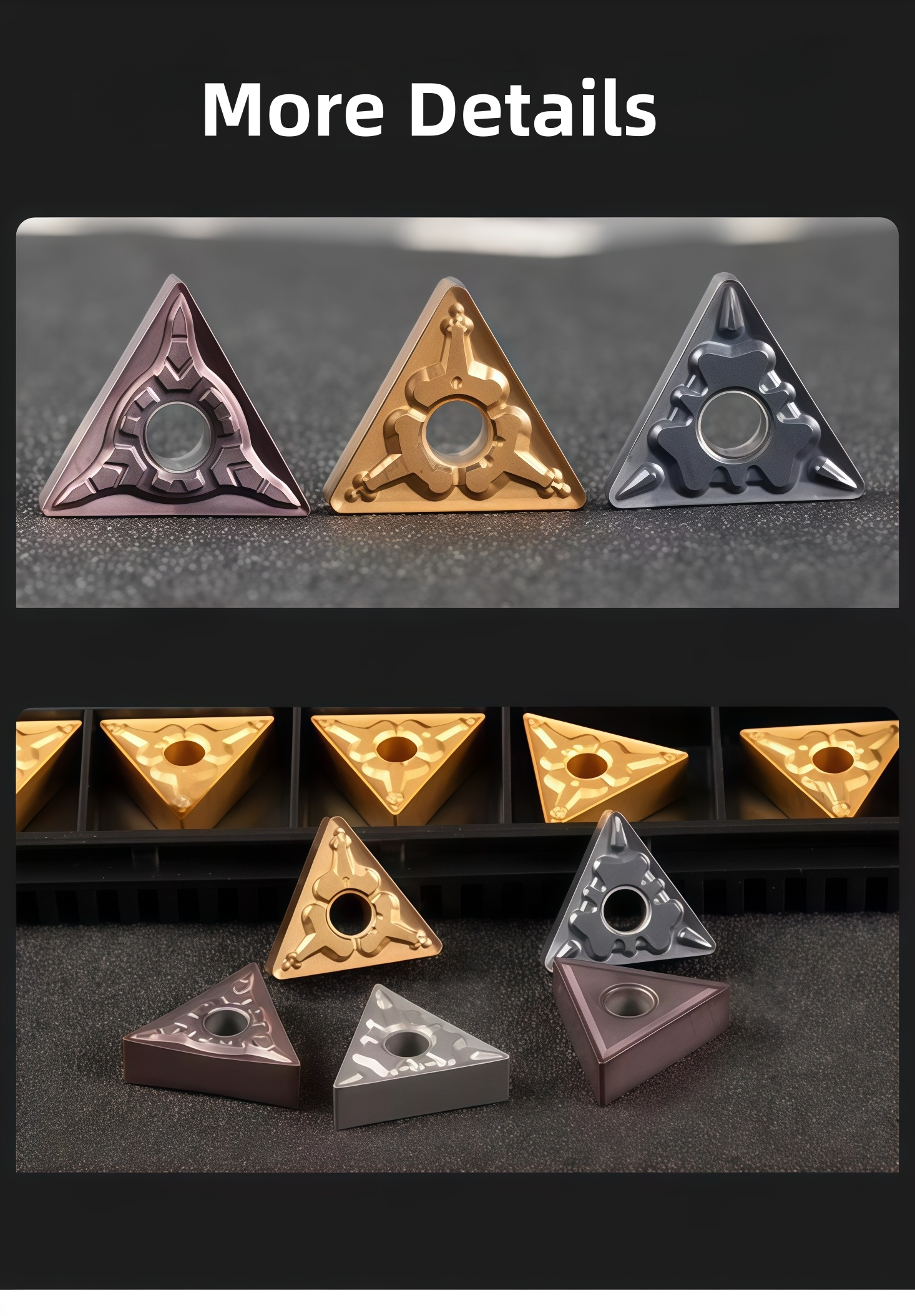
TNMG inserts are normally packed in compartment boxes to protect the cutting edges and maintain clear model, grade and batch identification. Final packaging details are confirmed according to the selected models and order quantity.
- Complete TNMG insert code, grade and chipbreaker
- Compatible tool-holder model
- Workpiece material and hardness
- Turning operation, feed and cutting depth
- Required quantity and packaging preference
If the full model is unavailable, send clear photographs of the insert marking, chipbreaker surface, side profile, package label and compatible holder.

◆Specifications & Size Chart
TNMG 160404, 160408 and 160412 are 60° triangular, negative-clearance turning insert designations with nominal corner radii of 0.4, 0.8 and 1.2 mm. The 16-size family normally uses a 9.52 mm inscribed circle, 4.76 mm thickness and approximately 3.81 mm fixing hole. The figures below are family-size references; the approved HY drawing for each complete grade and chipbreaker code determines the supplied insert dimensions.
| Base ISO Size | IC (mm) | S (mm) | Hole D1 (mm) | Corner Radius RE (mm) | Application Consideration |
|---|---|---|---|---|---|
| TNMG 160404 | 9.52* | 4.76* | 3.81* | 0.4 | Smaller nose radius; consider for lower feeds and finer profiles. |
| TNMG 160408 | 9.52* | 4.76* | 3.81* | 0.8 | General turning reference where finish and edge support must be balanced. |
| TNMG 160412 | 9.52* | 4.76* | 3.81* | 1.2 | Larger nose radius; assess cutting force, stability and feed capability. |
◆Specification Checklist by Model
| Parameter | Details to Confirm |
|---|---|
| Insert geometry | 60° triangular, double-sided TNMG form with 0° clearance and a fixing hole; check the actual chipbreaker and holder seat. |
| Nominal size and radius | 1604 size family; select 0.4, 0.8 or 1.2 mm radius according to feed, profile, finish and setup rigidity. |
| Carbide grade | The Overview names TBG2110, TBG2025, TBC2015 and TBD2025 as options; verify which grade is offered for each size and steel application. |
| Chipbreaker and coating | Confirm the exact finishing, medium or roughing geometry, substrate and PVD/CVD coating code. Coating color alone does not identify the grade. |
| Holder compatibility | Check TNMG 16 pocket, thickness, hole, clamp, seat, approach angle and tool hand against the holder manufacturer's specification. |
| Supply and packing | Overview reference: 10 pieces per plastic box. Confirm pack count, mixed-model supply, stock and labeling by complete order code. |
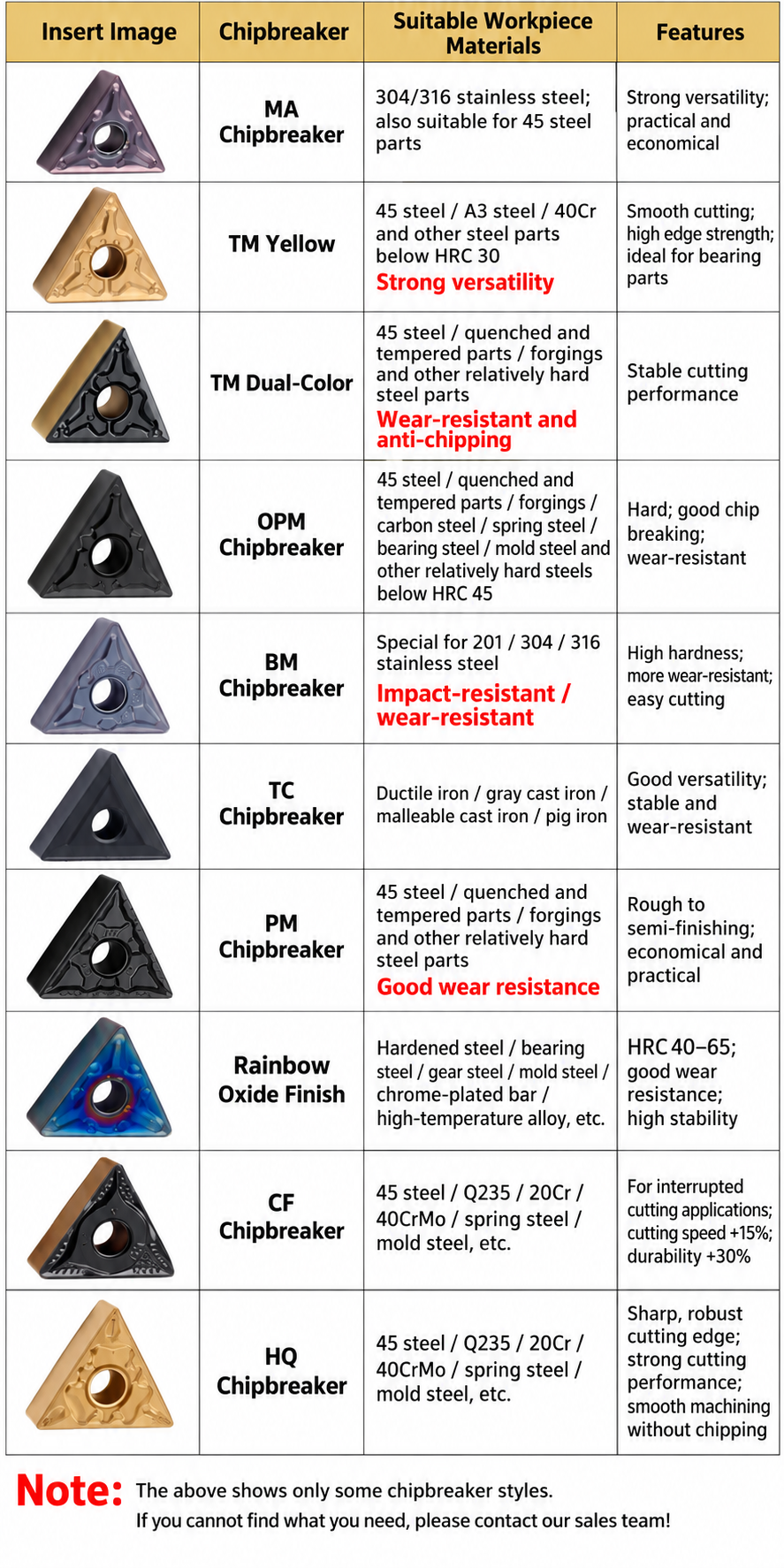
MA & TM Chipbreaker Reference
The supplied chipbreaker image describes MA as an option for stainless steel and selected steel parts, and shows two TM presentations for steel. These are qualitative series descriptions, not a dimensional chart or a grade-specific cutting recommendation.
| Chart Label | Application Shown | Confirm Before Selection |
|---|---|---|
| MA | 304/316 stainless steel and selected 45 steel parts | Actual TNMG size, carbide grade, coating and operating range |
| TM, yellow presentation | Selected carbon and alloy steels | Full code, steel hardness, grade and cutting conditions |
| TM, two-color presentation | Selected quenched-and-tempered steels and forgings | Full code, substrate, coating, edge preparation and interrupted-cut suitability |
◆How to Select a TNMG Insert
See the CNC Insert Selection Guide for additional shape, grade and radius checks.

◆Starting Cutting Data
The Overview quotes 160–220 m/min under selected conditions, without assigning a steel grade, chipbreaker, hardness, feed or depth of cut. Treat it as a non-universal reference. Obtain cutting data for the exact insert grade and steel material before selecting a starting speed, then adjust for machine rigidity, coolant and cut continuity.
◆Related Series & Technical References
Compare other turning geometries in the carbide turning and milling insert range. For a current TNMG series drawing, holder match, grade-specific cutting data or quotation, send the complete model and application details.
◆Carbide Insert Customization & OEM
Specify the insert around the machining operation, workpiece and holder. We can review standard replacements, application-specific geometry and private-label requirements using your insert designation, drawing or sample. Available grades, coatings, dimensions and order quantities are confirmed for each requested series.
Geometry & Chip Control
Review chipbreaker, rake, cutting-edge preparation, nose radius and corner design for the operation and workpiece. Confirm holder compatibility before approving a modified geometry.
Substrate & Coating
Select an available carbide grade and coating for the workpiece material, cutting conditions and desired balance of wear resistance and edge toughness.
Dimensions & OEM
Review insert size, thickness, locating and clamping features, tolerances, laser marking and private-label packaging against the approved specification.
◆Customization Options
Use the fields below when sending an inquiry. The exact options depend on the insert family and are confirmed in the quotation or approved drawing.
| Specification | Details to Confirm |
|---|---|
| Insert Type | Turning, milling, threading, grooving or drilling insert; send the designation or drawing. |
| Size & Fit | Shape, size, thickness, inscribed circle or edge length, hole or clamping form, and holder model. |
| Cutting Geometry | Chipbreaker, nose or corner radius, edge preparation, cutting direction and application-specific profile. |
| Grade & Coating | Workpiece group and grade, carbide substrate, coating system and wet or dry cutting conditions. |
| Tolerance & Inspection | Critical dimensions, profile requirements, inspection method and any required report. |
| OEM Presentation | Insert or box marking, label content, packaging format and quantity per pack. |
◆How to Request a Custom Insert

Send your insert requirements through our contact form or review our OEM and private-label service.
◆Carbide Insert Quality Control

Insert quality depends on the approved grade, geometry, coating and dimensional specification. We review the requirements at order confirmation and align the inspection scope with the insert series and any customer drawing. Share critical dimensions or documentation needs before production so they can be included in the agreed inspection plan.
01 · Incoming Material
Confirm the specified carbide grade or material documentation against the order requirements.
02 · In-Process Checks
Review dimensions and cutting-edge features during production against the approved specification.
03 · Final Inspection
Check the agreed dimensions, appearance, edge condition, coating identification and marking as applicable.
04 · Packing Review
Verify the item code, quantity, labels and protective packing against the approved order.
◆Inspection & Documentation
Inspection points and acceptance criteria should be agreed for the ordered series. For custom inserts, the approved drawing takes priority over a generic catalogue description.
| Check Area | What to Confirm |
|---|---|
| Dimensions & Fit | Insert size, thickness, corner radius, clamping features and any drawing tolerances. |
| Cutting Geometry | Chipbreaker, edge preparation, usable corners and profile where applicable. |
| Grade & Coating | Approved grade and coating designation; any requested verification method. |
| Appearance & Packing | Visible edge damage, marking, item code, count and packing format. |
| Requested Records | Inspection report, material or coating documentation, sample approval or batch identification when agreed. |
◆Order & Delivery
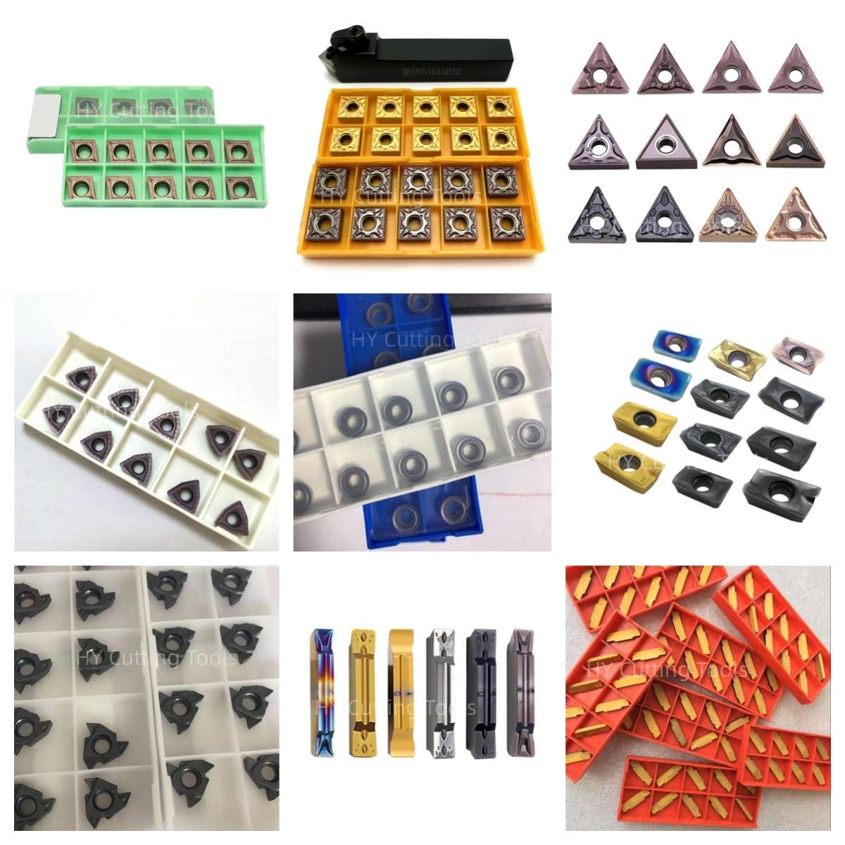

Share a line-by-line list of insert codes and quantities for a mixed-size quotation. Stock status, minimum quantity, sample requirements and production lead time are confirmed for each grade, coating and configuration.
Send your item list and quality requirements through our contact form for specification, availability and delivery confirmation.
◆Product FAQs
What is a TNMG turning insert?
TNMG is a 60° triangular, negative-clearance insert family with a fixing hole. A compatible holder can use its double-sided geometry for external turning and facing; profile access depends on the holder and approach angle. Confirm the complete size, chipbreaker and grade.
What changes between TNMG 160404, 160408 and 160412?
The last two digits specify nominal corner radii of 0.4, 0.8 and 1.2 mm. Choose the radius together with the chipbreaker, required finish, feed, part profile and setup rigidity. A larger radius does not automatically make one grade suitable for a heavier cut.
Can all three radii use the same holder?
They share the TNMG 1604 base designation, but verify the holder pocket, insert thickness, fixing hole, clamp, approach angle and part clearance. The nose radius and chosen chipbreaker can change usable profile access even when the insert seats in the same holder.
Which carbide grade should I select for steel?
Share the steel grade and hardness, finishing or roughing operation, continuous or interrupted cut, coolant and current wear pattern. The Overview lists TBG2110, TBG2025, TBC2015 and TBD2025 as options, but does not map each one to a specific 1604 radius or steel condition. Confirm the selected P-group grade by complete order code.
What is the difference between MA and TM chipbreakers?
The supplied chipbreaker chart describes MA for stainless steel and selected steel parts, and TM presentations for selected steels. It does not give a TNMG-size-specific feed and depth-of-cut range or map either geometry to every listed carbide grade. Confirm the complete model, coating and steel application before choosing; appearance alone is insufficient.
Can I use 160–220 m/min for every steel-turning setup?
No. The Overview gives that range only as a general reference under selected conditions. Obtain grade-specific starting data, including feed and depth of cut, for the steel grade and hardness, chipbreaker, coolant and cut continuity. Validate the settings with a trial cut.
◆Ordering & OEM FAQs
What should I send for a TNMG replacement inquiry?
Provide the original manufacturer, full insert code, grade and chipbreaker, photos of the marking and both faces, holder model, steel grade, cutting conditions, current wear issue and required quantity. Compare a proposed replacement in a controlled machining trial.
Can I order different radii or grades together?
Send a line-by-line list with each complete TNMG code, grade, chipbreaker and quantity. Mixed-model availability, minimum order quantity and dispatch time are confirmed by item. The Overview lists 10 pieces per box as its standard reference.
Can I request samples before a larger order?
Provide the complete code, holder, workpiece and planned test conditions. Confirm sample availability and evaluation criteria by grade; compare wear, chip control, surface finish and cost per accepted part under the same setup.
Are private-label packaging and customer SKU labels available?
The Overview lists neutral and private-label packaging, customer SKU and barcode labels. Send the artwork, marking requirements, pack quantity and expected order volume so feasibility, minimum quantity and lead time can be confirmed.
◆Guides & Technical References
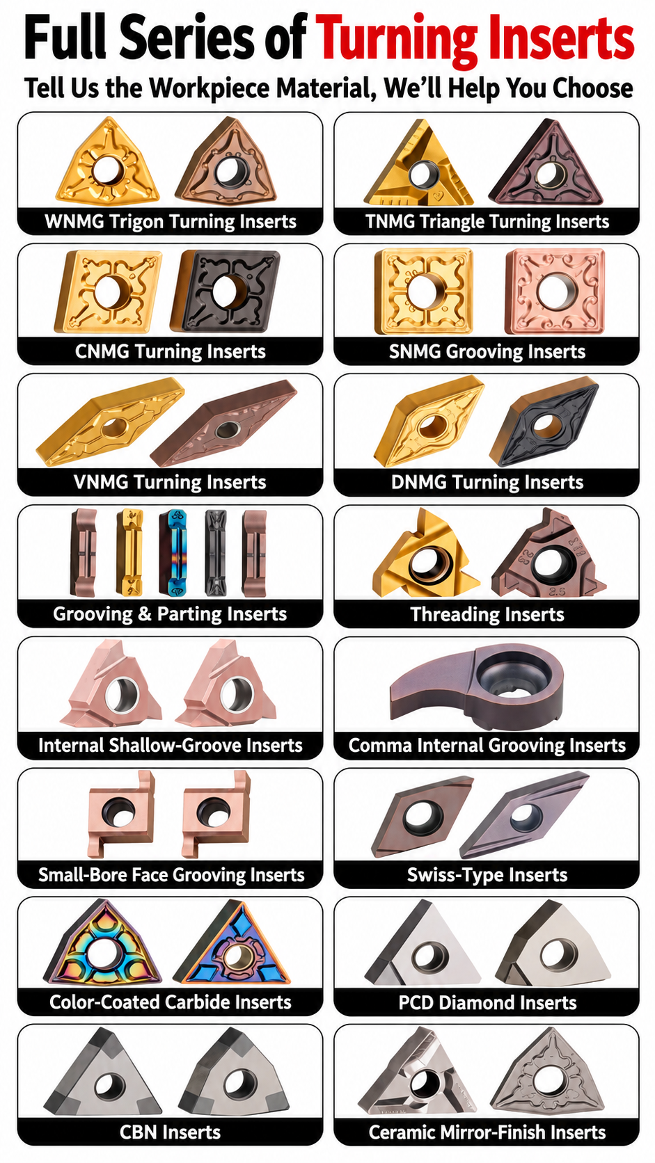
Use the CNC Insert Selection Guide for holder, grade, corner-radius and chipbreaker checks. The Carbide Insert Types Guide explains the wider insert families.
For the current TNMG drawing, grade-specific cutting data or quotation, send your complete insert and holder codes with the steel grade and quantity.
Need Sizes, Pricing or Custom Options?
Send us the required tool type, sizes, quantities, workpiece material and any OEM or custom requirements. We will confirm suitable specifications, availability, lead time and quotation details.
Drawings, size lists and reference photos are welcome.