How to Choose a Lollipop End Mill for Undercut Machining
Undercut machining presents a particular challenge: the cutting surface may be accessible to the cutter head, but not necessarily to the neck, shank, or tool holder.
A lollipop end mill, also known as a lollipop cutter or undercutting end mill, provides an alternative to conventional end mills through its spherical cutting head and reduced-neck geometry. This design allows the tool to reach certain surfaces beneath overhanging features or inside recessed profiles.
However, choosing a suitable cutter involves more than matching its diameter to the undercut.
A cutter may fit through the entry opening but collide with a nearby wall during machining. Increasing neck length may improve access while reducing rigidity. Selecting a larger wrap angle may expose more cutting edge but require a thinner neck.
The selection process must address three questions:
Geometric accessibility: Can the cutting edges reach the required surfaces?
Collision clearance: Can the complete tool assembly follow the intended machining path without interference?
Machining stability: Can the tool remove material with acceptable deflection, cutting conditions, and accuracy?
This guide explains how to evaluate undercut geometry, select cutter dimensions, compare common wrap angles, check neck clearance, and determine whether a standard or custom undercutting end mill is appropriate.
30-Second Takeaway
Choosing a lollipop end mill requires three checks: cutting-edge access to the undercut, collision clearance for the complete tool assembly, and sufficient rigidity for stable machining. Larger wrap angles or longer reduced necks may improve access, but can introduce stiffness limitations. Select the complete tool geometry—not the head diameter alone.
Quick Lollipop End Mill Selection Checklist
| Check | What to Verify |
|---|---|
| 1. Undercut geometry | Target profile, entry opening, and nearby walls |
| 2. Cutting head | Spherical diameter, cutting-edge coverage, and intended contact region |
| 3. Reach and neck | Required working reach, neck diameter, neck length, and transition geometry |
| 4. Complete assembly clearance | Shank, holder, fixture, entry, cutting, and retraction paths |
| 5. Machining stability | Actual overhang, cutting engagement, machine rigidity, and deflection risk |
| 6. Standard or custom | Available catalog geometries versus drawing-based requirements |
Start with the workpiece geometry. A cutter that reaches the target surface may still lack adequate clearance or machining stiffness.
1. What Makes Lollipop End Mills Suitable for Undercuts?
A lollipop end mill typically features a spherical or partially spherical cutting head supported by a reduced neck.
Compared with a conventional ball nose end mill, a lollipop end mill typically has cutting edges extending farther around the spherical head, depending on the cutter design. This can enable engagement with selected surfaces behind shoulders or within recessed profiles, subject to cutting-edge wrap angle, tool orientation, and clearance.
Common applications include:
- Machining curved surfaces beneath overhanging features.
- Finishing recessed contours in mold cavities.
- Underside deburring and edge breaking.
- Machining selected internal reliefs and complex profiles.
- Finishing accessible three-dimensional undercut surfaces. These operations may occur in mold manufacturing, medical component production, aerospace machining, and general precision engineering.
Is a Lollipop Cutter Always the Best Choice?
Not necessarily.
The appropriate cutting tool depends on the feature geometry, available access, and intended machining process.
| Undercut Feature | Tool or Process to Consider | Main Selection Reason |
|---|---|---|
| Curved or complex three-dimensional undercut | Lollipop end mill | Spherical cutting geometry provides access to selected hidden surfaces |
| Straight, constant-section T-slot | Dao phay rãnh chữ T | A dedicated profile may machine the slot more efficiently |
| Angular dovetail feature | Dovetail cutter | Cutting geometry matches the required inclined surfaces |
| Underside edge requiring deburring | Undercutting or back-deburring tool | Provides access to the rear edge |
| Feature blocked by the existing setup | Alternative fixturing or machining strategy | Changing the approach may be more practical than modifying the cutter |
For example, when an undercut consists of a continuous T-shaped slot, a dedicated T-slot cutter may be more efficient than using a spherical cutter to generate the entire profile.
Similarly, a dovetail cutter may be preferable when the feature has a consistent angled cross-section.
Tool selection should begin with the workpiece geometry and machining objective, not with a particular cutter type.
STANDARD PRODUCT REFERENCE
Explore the R1–R10 solid carbide lollipop ball nose end mill series for steel and aluminum, including reference neck and shank dimensions. Final tool geometry should be confirmed for your workpiece and machining setup.
View R1–R10 Lollipop End Mill Product & Specifications2. Step 1: Evaluate Undercut Geometry and Tool Accessibility
Before selecting a lollipop end mill, examine the workpiece geometry and identify the complete access path required to machine the feature.
Four questions should be answered first.
What Is the Shape of the Undercut?
Determine whether the required surface is:
- A curved three-dimensional profile.
- A recessed surface beneath a shoulder.
- A narrow internal groove.
- An underside edge requiring deburring.
- A special profile with defined dimensional tolerances. This establishes whether a spherical cutter is appropriate or whether a dedicated form tool would be more suitable.
How Large Is the Entry Opening?
The cutting head must be able to enter the machining area without contacting surrounding surfaces.
However, the entry opening alone does not determine accessibility.
A cutter may pass through the initial opening but still encounter interference when approaching the machining surface.
The complete insertion and machining paths must therefore be considered.
How Much Working Reach Is Required?
Required Working Reach refers to the distance the tool must reach into or across the workpiece to access the target feature from the selected setup.
It is an application requirement rather than a fixed catalog dimension.
When reviewing a cutter drawing, distinguish it from two related dimensions:
- Chiều dài cổ: The manufacturer’s specified axial length of the reduced-neck section.
- Tool Overhang: The actual projection of the tool from the holder or effective clamping reference.
- A longer neck does not automatically guarantee greater usable working reach because shank transitions, holder geometry, tool orientation, and neighboring surfaces may still limit access.

Figure 1. Conceptual illustration: working reach is an application requirement; neck length is a tool dimension; overhang is measured from the holder reference. Not to scale.
Can the Machine Maintain a Suitable Tool Orientation?
Some undercuts can be machined on a three-axis CNC machine using an appropriately shaped cutter.
Other features may require workpiece repositioning or multi-axis tool motion.
With five-axis machining, additional tool orientations can improve accessibility. However, machine travel limits, rotary-axis positions, workholding fixtures, and holder interference still need to be checked.
Geometrically Reachable Does Not Mean Stable to Machine
A tool may reach the target surface but remain unsuitable for the required cutting operation.
For example, reaching a deep undercut with a long, thin neck may create excessive deflection. Restricted space may also complicate chip evacuation and coolant delivery.
Accessibility should therefore be evaluated in two stages:
Geometric accessibility: The tool can reach the required surface without collision.
Stable machining accessibility: The operation can be performed with acceptable rigidity, chip evacuation, cutting conditions, and dimensional control.
Passing the first condition is necessary, but it does not guarantee the second.
The stability considerations are discussed further in Section 6.
Practical recommendation: Review the part drawing or 3D model, including the entry opening, target surface, adjacent walls, machining depth, and allowable tool orientations, before selecting the cutter.
3. Step 2: Select Cutter Diameter, Neck Diameter, and Reach
The geometry of a lollipop end mill determines both its accessibility and its mechanical behavior.
The most important dimensions are the cutting head diameter, neck diameter, neck length, shank dimensions, and actual tool overhang.
| Dimension | Function | Selection Consideration |
|---|---|---|
| Cutter Diameter (D) | Defines the spherical head size | Must suit the target profile and available entry space |
| Neck Diameter (d) | Provides clearance behind the cutting head | Must balance clearance with bending stiffness |
| Neck Length (Ln) | Defines the reduced-neck section | Must accommodate the required access geometry |
| Shank Diameter (Ds) | Determines clamping compatibility | Must suit the holder and available clearance |
| Chiều dài tổng thể (OAL) | Defines total physical tool length | Must suit the setup and machining requirements |
| Tool Overhang | Actual projection from the holder | Should be minimized where possible |
Dimensional labels and measurement datums differ between manufacturers. Always refer to the specific tool drawing when comparing neck length, reach, and length below shank.
Cutter Diameter: Match the Cutting Head to the Feature
The selected cutter diameter must accommodate the required surface geometry and available entry path.
A larger cutting head may provide a stronger cutting structure, but its size can restrict access.
A smaller cutter may enter tighter spaces, although its geometry may result in reduced stiffness or cutting capacity.
When selecting diameter, consider:
- Minimum available entry clearance.
- Required undercut radius or profile.
- Surface curvature.
- Intended cutting contact region.
- Nearby walls and obstacles. Do not assume that a cutter is suitable simply because its diameter is smaller than the nominal opening.
Neck Diameter: Balance Clearance and Stiffness
Neck diameter must be selected from the available workpiece clearance, not from head diameter alone.
However, reducing neck diameter can significantly reduce bending stiffness.
For a simplified, solid, circular beam with a uniform cross-section, the second moment of area is:
I = πd⁴ / 64 This means that bending stiffness is strongly influenced by the fourth power of diameter when material properties, unsupported length, and other relevant conditions remain unchanged.
Worked Example: Ø2 mm vs. Ø3 mm Neck Stiffness
Consider two ideal, solid, circular necks with the same material, unsupported length, boundary conditions and transverse load. In the simplified beam model, bending stiffness is proportional to the fourth power of neck diameter.
| Ideal neck diameter | Relative stiffness | Relative deflection |
|---|---|---|
| Ø2 mm | 1.00× | 5.06× |
| Ø3 mm | 5.06× | 1.00× |
Illustrative analytical comparison only—not measured cutter performance. A real lollipop end mill has nonuniform geometry, transitions, changing cutting forces and a compliant holder–spindle system. Do not use this ratio to predict actual surface accuracy or allowable cutting load.
However, this relationship is a simplified mechanical model, not a direct prediction of actual cutter performance.
Real cutting tools may have tapered necks, varying cross-sections, local geometry transitions, or internal coolant channels. Their effective stiffness can differ from that of a simplified solid, uniform-neck model.
For preliminary dimension selection, retain as much neck diameter as the clearance envelope permits.
Neck Length: Avoid Unnecessary Flexibility
A longer reduced neck may be necessary to reach deeply recessed surfaces.
However, increasing unsupported length generally increases bending deflection.
For a simplified cantilever under a transverse end load:
δ = FL³ / (3EI) Where:
- δ = deflection
- F = transverse force
- L = unsupported length
- E = elastic modulus
- I = second moment of area This equation assumes an ideal beam fixed at one end and subjected to a concentrated transverse force at its free end. In the simplified model, deflection increases with the cube of unsupported length.
Actual milling cutters are supported through a tool-holding system, and cutting forces vary with tool rotation, engagement, and contact position along the cutting edges. The tool holder and machine spindle also contribute to overall compliance.
Therefore, the equation should be used to understand relative stiffness trends, not to predict absolute cutter deflection without a more complete mechanical assessment.
Neck Length and Tool Overhang Are Not Interchangeable
When evaluating the setup, consider both the reduced-neck section and the complete unsupported tool assembly.
Dimension-selection principle: Meet the required geometry with the least unnecessary reduction in neck stiffness. Cutting setup and stability are evaluated in Section 6.
4. Step 3: Compare 220°, 270°, and 300° Wrap Angles
Cái wrap angle describes the angular coverage of the cutting region around the spherical head.
Common undercutting end mill designs include 220°, 270°, and 300° configurations.
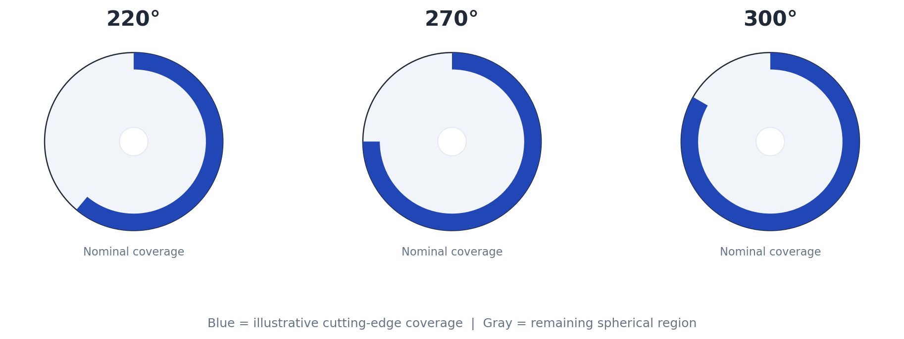
Figure 2. Idealized angular coverage only. The illustration does not imply identical flute geometry, neck diameter, stiffness, or guaranteed workpiece accessibility across tool families.
Different wrap angles provide different balances between cutting-edge coverage, access, and structural support.
| Wrap Angle | General Characteristics | Main Consideration |
|---|---|---|
| 220° | More limited cutting coverage, often allowing a comparatively stronger neck configuration | May restrict access to certain underside surfaces |
| 270° | Provides a balance of spherical cutting coverage and structural support in many standard designs | Still requires geometry-specific clearance verification |
| 300° | Provides greater cutting-edge coverage around the spherical head | May require a thinner neck and reduced stiffness |
These descriptions represent general design tendencies rather than guaranteed performance differences.
Does a Larger Wrap Angle Provide Better Accessibility?
A larger wrap angle can make additional portions of the spherical cutting surface available.
However, the nominal wrap angle does not represent guaranteed machining accessibility in a specific workpiece.
Actual accessibility depends on:
- Tool orientation.
- Required cutting contact region.
- Neck and shank clearance.
- Surrounding workpiece geometry.
- Tool holder dimensions.
- Machine kinematics and available tool motion.
- For example, a 300° cutter may provide greater cutting coverage than a 220° cutter within a comparable design family. However, this does not mean that it can automatically reach every surface that a 220° tool cannot.
Why Wrap Angles Cannot Be Compared in Isolation
Tools with different wrap angles may also have different neck diameters, cutting head profiles, flute geometries, and structural designs.
Even at the same nominal cutting diameter, a 220° cutter from one manufacturer and a 300° cutter from another may not provide a meaningful direct comparison of rigidity or machining capability.
The same limitation applies when comparing cutters with identical nominal wrap angles.
Two 270° cutters may still differ in head diameter, neck transition, cutting-edge preparation, flute geometry, and overall structural design.
Therefore, comparisons should be based on the complete cutter geometry rather than nominal wrap angle alone.
How Should the Wrap Angle Be Selected?
The selection process should follow four questions:
Which part of the spherical cutting edge must contact the target surface?
Does the selected wrap angle provide the necessary cutting coverage?
Can the neck remain clear of surrounding geometry?
Is the resulting cutter sufficiently rigid for the intended machining conditions?
A larger wrap angle should not be selected simply because it offers more cutting coverage.
The preferred configuration provides sufficient cutting access while retaining adequate structural rigidity.
5. Step 4: Check Neck, Shank, and Holder Clearance
One of the most important risks in undercut machining is interference between the non-cutting portions of the tool and the surrounding workpiece.
A cutter may reach the target surface while its neck, shank, or holder collides with another feature.
This makes clearance verification essential.
Why Cutter-Head Accessibility Is Not Enough
Consider an undercut beneath a projecting shoulder: even when the head reaches the target surface, the neck-to-shank transition or holder may interfere during entry, cutting, or retraction.
Check the Entire Tool Assembly
A complete interference review should include:
- Cutting head geometry.
- Non-cutting regions of the cutter.
- Reduced-neck diameter and length.
- Neck-to-shank transition.
- Shank diameter and geometry.
- Collet, chuck, or tool holder.
- Workholding fixtures and nearby features.
- Tool movement during entry, cutting, and retraction.
- Clearance should be checked throughout the machining operation, not only at the final cutting position.
Static Clearance Versus Dynamic Collision Checking
Static clearance determines whether the tool assembly can occupy a particular position without collision.
Dynamic clearance determines whether the assembly can move through the complete programmed path without interference.
This distinction is particularly important in five-axis machining.
When the tool orientation changes, the cutting head, neck, shank, and holder occupy a changing volume in space.
The resulting swept volume must be considered.
Checking only a limited number of discrete tool positions may miss interference occurring between those positions.
For complex multi-axis operations, use suitable CAM verification that accounts for the continuous or sufficiently resolved motion of the complete tool assembly.
Where available, machine-level simulation should also be used to review:
- Tool and holder interference.
- Fixture collisions.
- Rotary-axis motion.
- Machine travel limits.
- Entry and retraction movements.
- Simulation accuracy depends on the quality of the tool, holder, fixture, and machine models, as well as the verification method. A collision-free simulation does not automatically guarantee acceptable cutting stability or machining accuracy.
What Should You Do if the Neck Interferes?
Possible solutions include:
Reducing neck diameter where mechanically acceptable.
Changing the neck length or transition geometry.
Selecting a different cutter-head diameter.
Evaluating another wrap angle.
Changing the tool approach or orientation.
Modifying the setup or machining strategy.
Considering a custom cutter if standard configurations remain unsuitable.
6. Step 5: Evaluate Deflection and Machining Stability
After selecting neck geometry and working reach in Section 3, evaluate machining stability under the actual cutting engagement and tool-holding conditions.
Why Does Neck Geometry Affect Machining Stability?
As the simplified stiffness comparison in Section 3 illustrates, neck geometry affects tool compliance. In real undercut milling, forces pass from the engaged spherical edge through the neck, shank, and holder; the resulting deflection depends on tool orientation and cutting conditions.
If the tool lacks sufficient stiffness, excessive deflection may lead to:
- Dimensional errors.
- Poor surface finish.
- Chatter or vibration.
- Uneven cutting-edge loading.
- Accelerated wear.
- Premature tool failure. The actual response depends on both cutter geometry and cutting conditions.
Cutting-Force Direction Matters in Undercut Machining
Unlike a simple straight side-milling operation, undercut machining may involve contact with different regions of the spherical cutting head.
The direction of cutting forces can change according to:
- The engaged portion of the cutting head.
- Feed direction.
- Tool rotation.
- Tool orientation.
- Instantaneous cutting engagement. Depending on these conditions, cutting forces may cause deflection toward or away from the target surface. This can affect dimensional accuracy and surface quality.
Therefore, cutting conditions should be evaluated for the actual engagement geometry rather than assuming that the tool behaves like a conventional end mill of the same diameter.
Practical Ways to Improve Machining Stability
Set the actual clamping projection. After selecting the neck geometry in Section 3, use the shortest practical tool projection from the holder. Verify that the holder and transition remain clear throughout the path.
Control cutting engagement. Adjust radial engagement, axial engagement, and feed according to cutter geometry and machining conditions.
Select suitable tool geometry. Cutting-edge design, flute count, carbide substrate, and coating should be appropriate for the workpiece material and operation.
Maintain a rigid setup. Holder condition, tool clamping, workholding, and machine rigidity all affect machining stability.
Evaluate chip evacuation and cooling. Restricted cavities may create additional difficulties with chip removal and coolant access.
Verify cutting conditions. Use manufacturer recommendations and actual machining feedback to refine the process.
Why Is the Length-to-Diameter Ratio Important?
A length-to-diameter ratio can help screen comparable tool configurations, but define L and d first. For the ideal beam example below, L is the effective unsupported length of a uniform cylindrical section and d is that section’s diameter; this is not automatically the same as catalog neck length or total tool overhang.
Illustrative calculation · not a safe L/d limit
What Changes When L/d Increases from 5 to 8?
For the same solid circular neck diameter, material, transverse tip load, and ideal cantilever boundary condition, bending deflection varies with the cube of effective unsupported length. Increasing L/d from 5 to 8 therefore gives:
δ8d / δ5d = (8 / 5)³ ≈ 4.10
These numbers demonstrate sensitivity to length; they do not classify L/d = 5 as safe or L/d = 8 as unsafe. Real lollipop cutters have nonuniform geometry, changing forces, and holder compliance. Check the actual cutter assembly and application before specifying a limit.
However, there is no single universal ratio that determines whether a lollipop end mill is safe or stable.
Use this ratio as a preliminary screening indicator, not as a fixed acceptance threshold. Confirm the final configuration using relevant manufacturer information and application testing.
Why This Guide Does Not Provide Universal Speeds and Feeds
Cutting parameters for lollipop end mills depend on several interacting factors:
- Cutting head diameter.
- Neck diameter and length.
- Actual tool overhang.
- Flute geometry and coating.
- Workpiece material and hardness.
- Cutting engagement.
- Machine and holder rigidity.
- Required surface finish and tolerances.
- A short-neck cutter performing light finishing may require substantially different parameters from a long-neck cutter machining a difficult material. Using a generic feed-rate table without specifying these conditions may create misleading expectations.
Once the actual cutter specifications and application conditions are available, targeted cutting-parameter recommendations can be developed using manufacturer data, relevant application experience, and machining feedback.
The information in this guide is intended for preliminary tool selection and technical evaluation. Actual cutting parameters, tool life, and achievable tolerances must be established using the specific tool configuration, machine conditions, and appropriate machining trials.
7. Real Project: Custom R2 Lollipop End Mill Manufactured to Customer Drawing
The selection principles discussed above also apply when a customer already has a finalized cutter drawing. In such cases, the immediate requirement may be to reproduce a specified geometry rather than redesign the tool.
HY Cutting Tools completed a build-to-print project for a custom R2 lollipop end mill based on a customer-supplied drawing.
Customer-Specified Tool Geometry
| Tính năng của công cụ | Specified Dimension |
|---|---|
| Spherical Head Radius | R2 |
| Nominal Spherical Head Diameter | Ø4 mm |
| Reduced-Neck Diameter | Ø2 mm |
| Đường kính thân | Ø4 mm |
| Chiều dài tổng thể | 50 mm |
| Front-End Dimension | 10 mm |
| Tapered Transition | 60° |
The 10 mm front-end dimension is not necessarily the straight reduced-neck length; its reference points must be read from the original drawing.
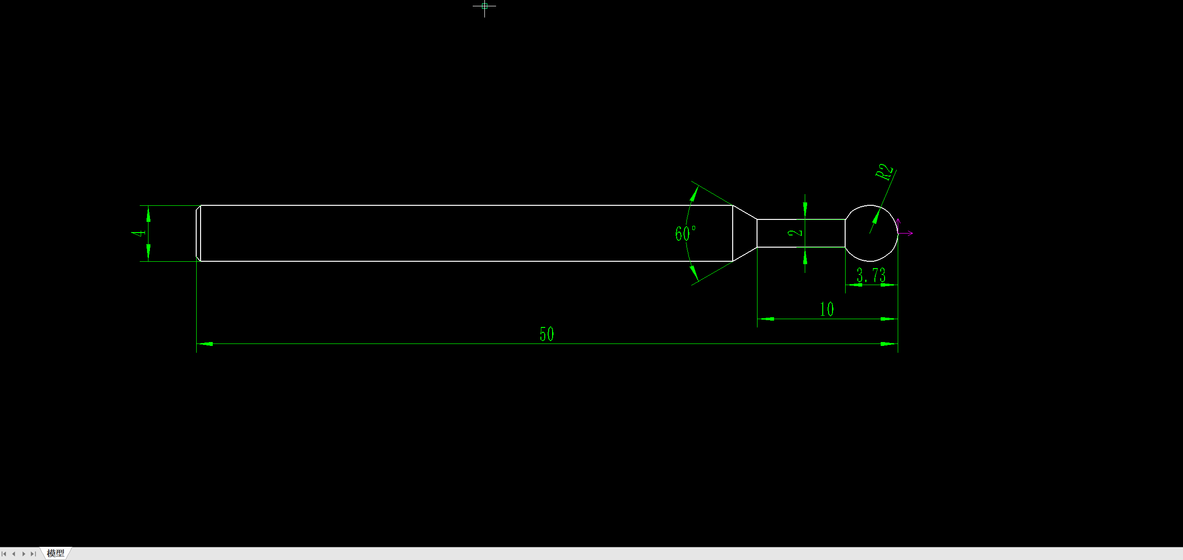
Customer-supplied drawing showing the R2 head, Ø2 mm reduced neck, Ø4 mm shank, and specified transition geometry.
Why the Geometry Matters
The nominal Ø4 mm spherical head and Ø2 mm reduced neck have a 1 mm difference between their radial envelopes. This can provide additional space behind the cutting head when approaching selected undercut or recessed surfaces, but it is not a guaranteed clearance allowance in an actual workpiece. Clearance must be evaluated against the part geometry and toolpath.
For the concentric nominal head and neck envelopes, the radial difference is (4 − 2) / 2 = 1 mm. This figure describes tool geometry only; it does not establish a collision-free machining allowance for the actual part.
The customer specified the 60° tapered transition. The reason for that particular angle was not documented, so it should not be described as a verified strength or clearance optimization. Similarly, the R2 spherical profile does not by itself establish the cutting-edge wrap angle or usable cutting coverage.
Manufacturing and Confirmed Outcome
HY Cutting Tools manufactured the tool according to the customer-supplied drawing, and the finished cutter met the customer’s specified manufacturing requirements. A real finished-tool video is available to document the manufactured geometry.
Actual finished R2 lollipop end mill with an Ø2 mm reduced neck and Ø4 mm shank, manufactured to a customer drawing. Video is muted on the page; the original media file may still contain audio.
This is a verified custom manufacturing case, not a documented comparison of design alternatives or cutting performance. The customer’s actual workpiece, machining results, tool life, and dimensional inspection measurements were not separately documented in the available project information.
Read the full custom R2 lollipop end mill manufacturing case study Explore Solid Carbide Lollipop Ball Nose End Mills R1–R10 for Steel and Aluminum
8. When Is a Custom Undercutting End Mill Necessary?
Standard lollipop end mills are available in various diameters, wrap angles, neck lengths, and cutting geometries.
For many applications, a suitable standard cutter may already exist.
Customization becomes relevant when the required geometry or operating conditions cannot be adequately satisfied by a standard configuration.
Common Reasons to Consider a Custom Cutter
| Application Challenge | Possible Custom Solution |
|---|---|
| Restricted neck clearance | Application-specific reduced-neck diameter |
| Special undercut profile | Customized spherical or form-cutting head |
| Deep recessed feature | Modified neck length and transition geometry |
| Difficult balance between access and rigidity | Optimized neck profile within manufacturing constraints |
| Nonstandard feature dimensions | Special cutting diameter or profile |
| Material-specific machining requirements | Appropriate substrate, edge preparation, and coating |
| Repeated machining of a dedicated component | Tool geometry designed around the recurring operation |
Customization should not automatically be considered the preferred solution.
A modified setup, alternative tool type, or different machining strategy may achieve the required result more efficiently.
Standard Tool or Custom Tool: A Practical Decision Process
Step 1 — Evaluate the Part Geometry
Identify the required undercut profile, entry opening, neighboring surfaces, and machining tolerances.
Step 2 — Review Available Standard Cutters
Check whether standard cutting diameters, neck lengths, and wrap angles can meet the geometric requirements.
Step 3 — Verify Accessibility
Confirm that the cutting head can reach the required surface from the available tool orientations.
Step 4 — Check Complete Assembly Clearance
Evaluate the neck, shank, holder, and intended tool motion for possible collisions.
Step 5 — Assess Machining Stability
Review neck stiffness, phần nhô ra của dụng cụ, cutting engagement, expected deflection, and required accuracy.
The custom R2 lollipop end mill project in Section 7 illustrates build-to-print manufacturing of customer-defined geometry; it does not establish that this geometry is the preferred solution for other undercutting applications.
Step 6 — Compare Alternative Solutions
If standard cutters cannot provide an acceptable balance between clearance and rigidity, compare alternative setups, fixturing changes, machining strategies, and custom tooling.
Consider:
- Tooling and manufacturing costs.
- Programming and setup time.
- Fixture modification requirements.
- Delivery lead time.
- Machining efficiency.
- Production quantity and repeat demand.
- Process verification requirements.
- Technical risks and expected consistency. Tooling cost, setup time, lead time, and production volume can often be compared quantitatively. Technical feasibility, machining risks, and verification requirements should be assessed using application-specific engineering evidence. Where reliable historical data are available, factors such as scrap rates, cycle-time variation, and process reliability may also be quantified.
For a prototype or small batch, changing the setup may be more practical than commissioning a dedicated cutter.
For recurring production, a custom cutter may justify its initial cost by reducing setup complexity or improving process efficiency.
Neither option is automatically cheaper.
The preferred solution should be based on total manufacturing cost, technical feasibility, and production requirements.
Step 7 — Consider Customization When Justified
If standard tooling and practical process alternatives cannot meet the combined requirements, a custom undercutting end mill may provide a suitable solution.
The decision should consider technical feasibility, tooling cost, required quantity, delivery time, and the expected repeatability of the operation.
Common Lollipop End Mill Selection Mistakes
The following mistakes can lead to unnecessary tooling costs, machining instability, or avoidable process failures.
| Common Mistake | Potential Consequence |
|---|---|
| Checking only the cutter diameter | Neck, shank, or holder interference |
| Selecting the largest wrap angle automatically | Unnecessary reduction in neck rigidity |
| Choosing excessive neck length | Increased deflection and chatter |
| Reusing standard ball nose cutting parameters | Excessive cutting loads or unstable machining |
| Checking only static tool positions | Undetected collision during tool movement |
| Selecting a custom cutter without evaluating process alternatives | Higher cost or complexity than necessary |
These issues are best addressed during tool selection, before committing to a production setup or special cutter design.
The objective is to select the most appropriate manufacturing solution—not necessarily the most specialized cutter.
9. What Information Should You Provide for Lollipop End Mill Selection?
Whether requesting a standard or custom lollipop end mill recommendation, complete application information helps the supplier evaluate feasibility and recommend suitable geometry.
The following details are especially useful.
| Information | What to Provide |
|---|---|
| Part Drawing or 3D Model | Dimensioned drawing, 3D model, or clear machining sketch |
| Undercut Geometry | Profile, radius, width, depth, and relevant tolerances |
| Entry and Clearance Conditions | Opening dimensions, adjacent walls, and restricted areas |
| Vật liệu phôi | Material grade and hardness, where applicable |
| Machine Configuration | Three-axis, four-axis, or five-axis machine |
| Tool Orientation and Machine Limits | Permitted tool orientations, axis travel restrictions, and rotary-axis limits |
| Required Working Reach | Distance needed to access the feature from the planned setup |
| Preferred Cutter Dimensions | Head diameter, neck diameter, neck length, and shank size, if known |
| Tool Holder Information | Holder type, clamping method, and relevant dimensions |
| Nguyên công gia công | Roughing, semi-finishing, finishing, deburring, or form machining |
| Surface and Accuracy Requirements | Required tolerances and surface finish |
| Existing Tooling Problems | Collision location, chatter, deflection, tool breakage, short tool life, or dimensional errors |
| Số lượng yêu cầu | Trial quantity, batch size, or estimated repeat demand |
Why Are Existing Tooling Problems Useful?
If the customer has already attempted the operation, the previous results can provide valuable technical information.
For example:
- Neck collision: The cutter may require a different neck diameter, length, or approach strategy.
- Excessive deflection: A more rigid configuration or reduced cutting load may be necessary.
- Poor surface finish: Cutting engagement, stiffness, edge geometry, or process conditions may need adjustment.
- Premature tool breakage: The cause may involve excessive load, insufficient rigidity, unsuitable geometry, or other operating conditions. Providing these observations helps distinguish a geometric access problem from a machining stability problem.
Request a Lollipop End Mill Evaluation
If you already have a finalized cutter drawing, we can review it for build-to-print manufacturing. If you are still evaluating tool geometry, please share the workpiece drawing and machining requirements for an initial technical discussion.
HY Cutting Tools supports standard and custom solid carbide cutting tool requirements, including application-specific cutter geometries.
For complex undercuts, restricted-access features, or nonstandard profiles, you can share your part drawing and machining requirements for an initial tooling review.
Depending on the information provided, we can discuss suitable cutter diameters, neck configurations, cutting geometry, and potential customization options.
Send us your drawing, workpiece material, machining requirements, and required quantity to discuss a suitable tooling solution.
Request custom cutting tool manufacturing
Câu hỏi thường gặp
What Is the Difference Between a Lollipop End Mill and a Ball Nose End Mill?
A conventional ball nose end mill has a hemispherical cutting end primarily used for contouring and profiling. A lollipop end mill typically provides cutting edges farther around its spherical head and has a reduced neck. Depending on wrap angle, orientation, and clearance, this may provide access to underside and recessed surfaces that a conventional ball nose cutter cannot reach in the same setup.
Are Lollipop End Mills and Undercutting End Mills the Same?
The terms are often used interchangeably, particularly for spherical-head cutters with reduced necks. However, product definitions and classifications may vary between manufacturers. Always check the cutting head geometry, neck dimensions, and intended application rather than relying on the product name alone.
Can a Lollipop End Mill Machine Undercuts on a 3-Axis CNC Machine?
Yes. Certain undercuts can be machined on a three-axis CNC machine if the cutter geometry and fixed tool orientation provide sufficient access. However, restricted approach directions may limit the machining strategy. Clearance, cutting engagement, deflection, and stability must still be verified.
Is a 300° Lollipop End Mill Better Than a 220° Cutter?
Not necessarily. A 300° cutter provides greater nominal cutting-edge coverage, but its design may require a thinner neck. A 220° configuration may offer better rigidity in some comparable designs. The correct choice depends on the required contact region, complete cutter geometry, and available clearance.
How Do I Prevent Neck Collision During Undercut Machining?
Evaluate the complete cutter geometry, including the cutting head, neck, shank, and holder. Verify the entire programmed toolpath rather than checking only individual tool positions. For multi-axis operations, consider the swept volume created by changes in tool orientation.
Why Does a Long-Neck Lollipop Cutter Vibrate?
A long, reduced-diameter neck can have relatively low bending stiffness. Excessive overhang, cutting forces, or unstable clamping may cause deflection and chatter. Using the shortest practical setup, preserving neck diameter, controlling cutting engagement, and improving rigidity can help reduce vibration.
Can I Use the Same Cutting Parameters as a Standard Ball Nose End Mill?
Not automatically. The reduced neck of a lollipop cutter may introduce different stiffness limitations. Speeds, feeds, and cutting engagement should be selected based on the actual tool dimensions, workpiece material, cutting conditions, and machine setup.
What Information Is Needed to Quote a Custom Lollipop End Mill?
A dimensioned tool drawing or workpiece drawing is the best starting point. Useful details include the required cutting profile, head diameter, neck dimensions, workpiece material, machine configuration, tolerances, and quantity. Information about available clearance or problems with an existing cutter can also help the technical review.
Can a Custom Undercutting End Mill Be Manufactured From a Part Drawing?
A part drawing or 3D model can be used to begin evaluating a custom cutter design. The tooling supplier can review the required profile, available access, cutter geometry, and manufacturing constraints. Final feasibility, dimensions, tolerances, and pricing depend on the specific application and technical requirements.
When Should I Order a Custom Lollipop Cutter?
Consider customization when standard tools cannot satisfy the combined requirements for profile geometry, accessibility, neck clearance, rigidity, and machining accuracy. Alternative setups or processes should also be evaluated to determine the most practical solution.
Kết luận
Choosing a lollipop end mill for undercut machining requires more than matching the cutting head diameter to the feature.
A suitable cutter must satisfy three essential requirements:
The cutting edges must reach the required surface.
The complete tool assembly must remain clear throughout the machining path.
The cutter must provide sufficient rigidity and appropriate cutting conditions for the intended operation.
Sections 2–6 explain how to assess these requirements through geometry evaluation, cutter dimension selection, wrap angle comparison, clearance verification, and machining stability analysis.
Cutter diameter, wrap angle, neck geometry, required working reach, and actual tool overhang are closely related.
Increasing cutting-edge coverage or extending the neck may improve access, but these changes can introduce new limitations in stiffness and machining stability.
Effective selection therefore begins with the workpiece geometry, continues through collision and stability assessment, and ends with a practical comparison of standard tooling, process alternatives, and custom solutions.
A custom undercutting end mill is most valuable when its geometry solves a clearly defined machining problem that standard tooling or practical process adjustments cannot adequately address.
HY Cutting Tools welcomes part drawings and application requirements for technical evaluation of standard and custom carbide cutting tools. Submit your custom tool request.