
Can a Custom Step Drill Hold 0.01 mm-Level Tolerances?
A real drawing-to-tool manufacturing example from HY Cutting Tools
When a custom step drill is specified with 0.01 mm-level critical dimensions, the challenge is not simply producing the required geometry. Buyers also need to know which features require tighter control, how those dimensions are verified before delivery, and whether the tool performs as required under actual machining conditions.
Quick Answer
-
Yes—selected critical dimensions can be controlled at the 0.01 mm level.
This is achievable when the drawing clearly defines the feature and its tolerance.
See the real multi-step drill example -
The tolerance belongs to a specific feature, not automatically to the whole tool.
Step diameters, axial lengths, chamfers and angles can all carry different requirements.
See how 0.01 mm-level tolerances should be interpreted -
Tool tolerance and finished-hole tolerance are different.
The drill can meet its drawing while the finished result is still affected by the machine, holder, runout, material and cutting conditions.
See the difference between tool and hole tolerance -
Actual machining still has to validate the process.
In this project, the finished tool passed the customer’s machining test, and the customer continued placing repeat orders.
See how the sample was validated in this project
Real Example: 0.01 mm-Level Control on a Custom Multi-Step Drill
One HY Cutting Tools project combined Ø6.5 mm, Ø11 mm and Ø14 mm sections into a single solid carbide multi-step tool.
The approved drawing did not apply one blanket tolerance to the entire drill. Instead, individual features were assigned different requirements according to their function.
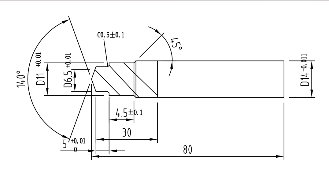
Confirmed Tool Geometry
Selected Drawing Tolerances from the Project
| Feature | Drawing Size | Drawing Tolerance |
|---|---|---|
| Step diameter | Ø6.5 mm | +0.01 mm |
| Transition angle | 45° | ±0.1° |
| Chamfer | C0.5 | ±0.005 mm |
| Radius | R0.15 | ±0.02 mm |
| Diameter | Ø14 mm | -0.01 mm |
| Axial length | 5.0 mm | +0.01 mm |
| Point angle | 140° | ±1° |
| Axial dimension | 4.5 mm | ±0.1 mm |
| Step diameter | Ø11 mm | +0.01 mm |
These requirements show why a statement such as “high-precision step drill” is not specific enough.
Several dimensions in this project were specified at the 0.01 mm level, while the C0.5 feature carried a tighter ±0.005 mm tolerance. Other dimensions and angles used different limits.
Precision was therefore defined feature by feature, not with one tolerance for the whole tool.
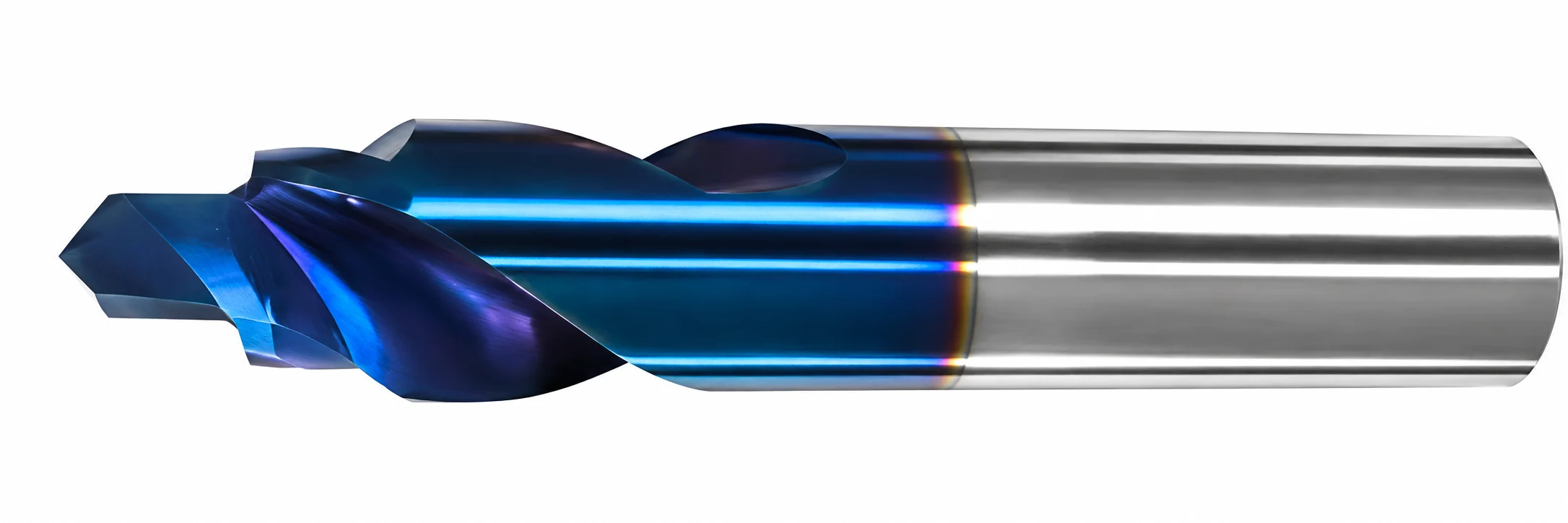
The tool was manufactured and inspected against the confirmed drawing before delivery.
Project Result
The finished tool passed the customer’s machining test and was approved for production use.
The customer continued placing repeat orders after the initial validation.
This gives the project a complete validation path:
For a buyer, this is more meaningful than a general claim that a supplier can make “precision tools.”
What Does 0.01 mm-Level Tolerance Mean on a Step Drill?
A tolerance only becomes meaningful when it is attached to a defined feature.
What “0.01 mm” May Refer To on a Step Drill Drawing
| Feature | What the Tolerance May Refer To |
|---|---|
| Step diameter | Diameter size |
| Step length | Axial length or shoulder location |
| Shoulder | Transition position |
| Chamfer / radius | Defined transition geometry |
| Shank diameter | Mounting dimension |
| Feature relationship | Position, coaxiality or another drawing-defined requirement |
Instead of writing only “0.01 mm tolerance,” a clearer RFQ would specify the exact feature, for example:
This tells the manufacturer exactly which feature requires tight control and avoids applying the same tolerance to unrelated dimensions.
One step diameter may directly affect the finished bore, while an angular or axial feature may allow a wider tolerance without affecting part function.
Applying unnecessarily tight tolerances to every dimension can increase manufacturing and inspection difficulty without improving the finished part.
Tool Tolerance Is Not the Same as Finished-Hole Tolerance
Tool Tolerance
Tool tolerance describes the physical dimension manufactured on the drill.
- Ground according to the approved drawing
- Measured before delivery
- Compared with the specified drawing tolerance
- Verified as part of tool manufacturing
Finished-Hole Tolerance
Finished-hole tolerance describes the result produced in the actual workpiece.
- Spindle runout
- Toolholder runout
- Machine rigidity
- Tool overhang
- Workpiece material and hardness
- Cutting speed and feed
- Coolant condition
- Chip evacuation
- Cutting-edge wear
Runout is one reason tool dimensions alone cannot guarantee the finished-hole result. For further guidance, see Sandvik Coromant’s guide to minimizing drill runout .
When a Step Drill Alone May Not Be Enough
A multi-step tool can combine several hole features into one operation, reducing tool changes and positioning steps.
A secondary finishing process may still be required when the finished part needs especially tight control of:
Depending on the application, this may involve reaming, boring, honing or grinding.
The process should be selected from the finished-part requirement, not simply from how tightly the drill itself can be manufactured.
What Buyers Should Define on the Drawing
For tight-tolerance tooling, a clear drawing is more useful than a general request for “high precision.”
The RFQ should identify the features that actually affect part function.
| Drawing Item | Information to Provide |
|---|---|
| D1 / D2 / D3 | Nominal diameter and tolerance |
| Step length | Axial length and tolerance |
| Shoulder | Position and/or angle |
| Transition | Chamfer, radius or angle |
| Shank | Diameter and tolerance |
| Feature relationships | Position, coaxiality or another requirement if needed |
| Workpiece | Material and hardness |
| Hole condition | Through / blind, depth and coolant condition |
It is useful to distinguish between:
This gives the manufacturer a clearer basis for tool design, grinding and inspection while avoiding unnecessary cost on features that do not need extreme control.
How We Verify Critical Dimensions Before Delivery
Critical dimensions are checked against the approved drawing before delivery.
Measured dimensions are compared with their specified tolerance limits, with inspection focused on the features identified as critical.
Inspection records are retained as part of the internal quality-control process.
The original internal inspection report for this project is not published here. The selected drawing requirements have been compiled in this article to show how the tolerance requirements were defined and controlled.
This stage verifies the physical tool. It does not replace customer-side machining validation.
How Was the Sample Validated in This Project?
After dimensional verification, the tool still had to prove itself in the customer’s machining process.
What the Machining Trial Should Check
Test conditions should also remain controlled. Machine, holder, material, coolant, speed, feed and overhang can all influence the result.
Changing several variables at the same time makes it difficult to determine whether a result comes from the tool or from the machining setup.
What Happened in This Project?
The customer tested the finished multi-step tool in the actual application.
The tool passed the machining test and was approved for continued use.
The customer then continued placing repeat orders for the same design.
- Dimensional verification confirmed the tool.
- Customer machining confirmed the application.
- Repeat orders confirmed continued acceptance in production.
What to Confirm Before Repeat or Small-Batch Production
Once the initial tool has passed testing, buyers should lock the main production conditions before increasing quantity.
For distributors, importers and machining suppliers, repeatability across future orders can matter just as much as the first successful sample.
FAQ
Can a custom step drill hold 0.01 mm-level tolerances?
Yes. Selected dimensions can be manufactured and verified at the 0.01 mm level when the drawing clearly defines where that requirement applies.
Can a step-drill drawing include tolerances tighter than 0.01 mm?
Yes. In this project, the C0.5 feature was specified at ±0.005 mm. Each requirement must be evaluated individually.
Does a 0.01 mm tool tolerance guarantee a 0.01 mm finished hole?
No. Finished-hole accuracy also depends on the machine, holder, runout, workpiece, rigidity and cutting conditions.
Was the tool validated in actual machining?
Yes. The customer tested the tool, approved it for continued use and subsequently placed repeat orders.
How are critical dimensions verified before delivery?
They are checked against the approved drawing, with verification focused on the dimensions identified as critical.
Should buyers test a sample before placing a larger order?
Yes. Testing should be carried out under conditions as close as possible to the intended production setup.
What information should I provide for a quotation?
Provide the drawing, critical dimensions and tolerances, workpiece material, hole depth, machining conditions and required quantity.
Have a Custom Step Drill Drawing?
Send us your drawing, workpiece material, quantity and critical tolerance requirements for review.