
2-, 3-, 4- and 5-Flute End Mills for Aluminum: Geometry, Performance and Cutting Strategies
Flute count affects chip evacuation, tool rigidity and feed potential in aluminum milling. However, more flutes do not automatically mean higher productivity.
A three-flute cutter designed for full slotting and a five-flute cutter designed for high-efficiency roughing may require very different cutting conditions.
The key is to evaluate flute geometry, chip control, radial engagement (ae), axial depth of cut (ap) and cutting strategy together.
Explore This Guide
Comparing 2-, 3-, 4- and 5-Flute End Mills for Aluminum
| Sáo | Typical Geometry | Application Considerations | What to Verify |
|---|---|---|---|
| 2F | Fewer cutting edges; potentially larger chip spaces | Full slotting, pocketing and operations requiring chip clearance | Flute capacity, edge strength and chip evacuation |
| 3F | Balance of chip space, cutting edges and core strength | General aluminum milling, slotting, profiling and roughing | Helix angle, flute geometry and recommended engagement |
| 4F | Additional cutting edges; potentially stronger core | Profiling, finishing and selected roughing operations | Aluminum-specific geometry, chip space and allowable ae/ap |
| 5F | Multiple cutting edges; specialized designs may include chip splitters and variable pitch | High-efficiency milling and specialized aluminum roughing | Chip-breaking features, engagement limits and cutting data |
Core diameter, flute depth, rake geometry and edge preparation can vary significantly between cutters with the same flute count.
A conventional four-flute steel-cutting end mill should not be considered equivalent to a four-flute cutter specifically designed for aluminum.
How Flute Geometry Changes Performance
Core Diameter and Chip Space
A larger core generally improves bending stiffness but reduces available flute space.
This trade-off becomes important during full-width slotting, where chips must escape from a confined cutting channel.
Compare the actual flute cross-section. Two-flute cutters do not always provide sufficient chip space, and four-flute cutters are not necessarily unsuitable for aluminum.
Helix Angle and Rake Geometry
Many aluminum-specific end mills use positive rake geometry and polished flute surfaces to reduce cutting resistance and support chip evacuation.
Helix angles of 35°, 40° and 45° are found in different aluminum-cutting designs.
A higher helix angle can provide smoother cutting engagement, but it also changes axial force components. Its suitability depends on the complete tool geometry and machining operation.
For example, HY Cutting Tools’ Dao phay nhôm đầu phẳng hợp kim nguyên khối 3 me không phủ features a 35° helix and mirror-polished flutes.
Cutting Edge and Chip-Breaker Design
Cutting-edge preparation must balance sharpness and strength.
Serrated edges and chip splitters can shorten chips and modify cutting loads during roughing. Their effect helps explain why specialized roughing cutters behave differently from conventional smooth-edge tools with the same flute count.
For additional factors affecting performance, including carbide substrate, edge preparation, runout and manufacturing consistency, read Vì sao dao phay nhôm cùng đường kính cho hiệu quả khác nhau?.
Match Flute Count to the Cutting Strategy
Full Slotting — ae = 100% D
Full-width slotting produces substantial chip volume within a restricted cutting zone.
Two- and three-flute aluminum-specific end mills are common choices because suitable designs provide space for chip evacuation.
Higher-flute-count cutters are not automatically excluded. However, their full-slotting capability must be supported by manufacturer cutting data.
Side Milling and Profiling
At reduced radial engagement, chip evacuation may become less restrictive.
Aluminum-specific three- and four-flute cutters can provide additional cutting contacts and suitable rigidity for profiling and finishing.
The actual advantage depends on radial width, axial depth, tool projection and machine stability.
High-Efficiency Milling — Low ae, Higher ap
High-efficiency milling (HEM) commonly combines reduced radial engagement with greater axial cutting depth and controlled cutter engagement.
For example, GWS ASR5 five-flute aluminum roughing data include:
ae = 30% D, ap = 2D
ae = 10% D, ap up to the specified maximum length of cut
These are manufacturer-specific application guidelines, not universal recommendations for four- or five-flute cutters.
The complete engagement comparison appears in Section 5.
Serrated Roughing Geometry
Flute count is not the only consideration in roughing.
HY Cutting Tools’ 3-Flute Polished Roughing End Mill for Aluminum uses serrated cutting edges and polished flute surfaces to support chip control during stock removal.
Compared with a smooth-edge cutter of the same flute count, serrated geometry changes chip formation and the resulting surface condition.
Allow appropriate finishing stock where a smooth final surface is required.
Feed Rate, Flute Count and Radial Chip Thinning
Table Feed Calculation
Table feed is calculated as:
Where:
Vf = table feed (mm/min)
n = spindle speed (rpm)
z = number of effective cutting teeth
fz = feed per tooth (mm/tooth)
Assume 12,000 rpm and a nominal feed per tooth of 0.04 mm:
| Sáo | Tính toán | Table Feed |
|---|---|---|
| 2F | 12,000 × 2 × 0.04 | 960 mm/min |
| 3F | 12,000 × 3 × 0.04 | 1,440 mm/min |
| 4F | 12,000 × 4 × 0.04 | 1,920 mm/min |
| 5F | 12,000 × 5 × 0.04 | 2,400 mm/min |
Increasing flute count from two to five does not automatically produce a 2.5-fold increase in actual productivity.
The calculation assumes all cutters can operate at the same feed per tooth. Actual chip load depends on tool geometry, cutting engagement, chip evacuation and machine capability.
Radial Chip Thinning
At low radial engagement, maximum chip thickness can be smaller than the programmed feed per tooth.
For simplified peripheral milling with an approximately 90° entering angle and ae ≤ 0.5D:
Where:
hmax = maximum chip thickness
ae = radial width of cut
D = cutter diameter
At ae/D = 0.10:
If the programmed fz is 0.05 mm/tooth:
This helps explain why low-radial-engagement machining may require feed-per-tooth compensation.
Corner-radius and ball-nose cutters may require corrections for effective entering angle and axial cutting depth. Variable-helix and variable-pitch designs can also change engagement timing and cutting-force distribution.
Runout, deflection and actual edge geometry introduce additional differences. Use cutter-specific data before applying chip-thinning compensation.
How Specialized 5-Flute End Mills Rough Aluminum Under Controlled Engagement
Two established cutting-tool manufacturers provide useful examples of five-flute aluminum roughing designs.
GWS Alumigator ASR5 — Five-Flute Roughing
GWS Tool Group’s Alumigator ASR5 series uses specialized roughing geometry, unequal tooth indexing, chip breakers and polished flutes.
The Series 1500 configuration also provides through-coolant capability.
Its published cutting data for aluminum alloys 6061 and 7075 show how radial and axial engagement are combined.
Official technical reference: GWS Alumigator ASR5 — Speed & Feed Guide (Series 1500)
Kennametal KOR5 DA — Application-Specific Cutting Geometry
Kennametal’s KOR5 DA is another five-flute aluminum roughing system.
Its design incorporates:
Chip splitters for improved chip control
Specialized flute geometry
High-efficiency and trochoidal milling capability
Internal coolant and selected Safe-Lock shank configurations
Kennametal also publishes maximum axial depths, radial engagement limits and feed multipliers.
Official product reference: Kennametal KOR5 DA — Product Specifications and Application Data
Published Engagement Guidelines for Two Specialized 5-Flute Cutters
The following table compares selected manufacturer-published engagement limits.
| Radial Engagement (ae/D) | GWS ASR5 — Maximum ap | Kennametal KOR5 DA — Maximum ap |
|---|---|---|
| 100% D | 0.25D | 0.25D |
| 50% D | 0.5D | 0.5D |
| 30% D | 2D | 2D |
| 10% D | Maximum specified length of cut (LOC Max) | Model-specific maximum axial depth (Ap1 Max) |
Important: How to Interpret These Values
The matching engagement ratios are manufacturer-published application guidelines, not independent comparative test results.
The available documents do not establish why the selected ratios are identical. They should not be treated as proof of equivalent cutting performance or as universal operating limits for five-flute end mills.
At 10% radial engagement, GWS uses LOC Max, while Kennametal specifies Ap1 Max. These are different catalog designations for cutter-specific axial limits; neither is a fixed numerical depth in this comparison. The actual permitted depth must be checked against the exact tool dimensions and manufacturer’s specifications.
The two series also have different cutter geometries, cutting speeds and feed recommendations.
What the data demonstrate
At full-width engagement, axial cutting depth is restricted. As radial engagement decreases, greater axial depth may be permitted for these particular tools.
This relationship helps explain how specialized five-flute cutters can support high-efficiency aluminum roughing.
Their performance depends on the complete cutting system:
It does not come from flute count alone.
When Higher Flute Counts Require Extra Caution
Four- and five-flute cutters require closer application review under the following conditions:
| Điều kiện | Main Risk | What to Check |
|---|---|---|
| Rãnh toàn chiều rộng | Chip packing and chip recutting | Manufacturer-approved slotting depth, feed and chip evacuation |
| Deep or enclosed pockets | Poor chip removal from the cutting zone | Pocket geometry, chip flow and coolant or air delivery |
| Long tool overhang | Deflection and unstable cutting | Tool projection, holder rigidity and engagement |
| Heavy engagement without verified cutting data | Excessive cutting load or poor chip control | Recommended ae/ap, edge geometry and machine capability |
These conditions require verification. They are not absolute restrictions.
The absence of internal coolant alone does not make a cutter unsuitable for aluminum. External coolant, air delivery and flute geometry may provide adequate chip removal under appropriate conditions.
For detailed troubleshooting of aluminum adhesion and chip packing, read Nhôm bám dao phay: Kiểm tra gì trước khi thay dao?.
Technical Checklist for Cutting Tool Distributors
Before recommending, comparing or replacing aluminum end mills with different flute counts, confirm:
| Verification Item | Thông tin bắt buộc |
|---|---|
| Hình học dụng cụ | Flute count, helix angle, core geometry, cutting-edge profile and flute finish |
| Vật liệu phôi | Aluminum alloy and material condition |
| Nguyên công gia công | Full slotting, side milling, profiling, finishing or HEM |
| Cutting Engagement | Recommended ae/D and ap/D for the exact tool |
| Thông số cắt | Vc, fz and chip-thinning compensation where applicable |
| Chip Control | Chip-breaker design and coolant or air requirements |
| Application Evidence | Tool model, tested conditions and documented results |
For micro-milling, additional factors include minimum chip thickness, edge radius, spindle runout and tool stiffness.
Do not assume that a two-flute tool is automatically preferable for every micro-diameter application.
For a specific micro-tool configuration, see HY Cutting Tools’ 2-Flute Polished Micro Square End Mill for Aluminum.
Câu hỏi thường gặp
Can a 4-flute end mill cut aluminum?
Yes. An aluminum-specific four-flute cutter can be suitable for profiling, finishing and selected roughing operations.
Its geometry, chip space and recommended cutting engagement must match the application.
Can a 5-flute end mill be used for full slotting?
Yes, when the specific tool is designed and rated for the operation.
Both the GWS ASR5 and the referenced Kennametal KOR5 DA publish full-width slotting conditions with limited axial depth.
These conditions are not transferable to all five-flute cutters.
Does increasing flute count always improve material removal rate?
Không.
Material removal rate can be calculated as:
Where:
Q = material removal rate (cm³/min)
ap = axial depth of cut (mm)
ae = radial width of cut (mm)
Vf = table feed (mm/min)
Actual productivity depends on cutting engagement and achievable feed rate, not flute count alone.
Is a higher flute count always better for finishing?
Không.
Surface finish also depends on runout, edge condition, chip evacuation, feed per tooth, tool deflection and machining stability.
A higher flute count may be beneficial under suitable conditions, but it cannot compensate for poor tool geometry or an unstable setup.
Kết luận
For aluminum milling, flute count must be evaluated together with cutting geometry, chip control and engagement conditions.
Two-, three-, four- and five-flute cutters can all be effective when their designs match the intended machining strategy.
For cutting tool distributors, the decisive information is not simply the number of flutes. It is the manufacturer’s verified cutting data, application limits and the consistency of the supplied tool geometry.
Explore HY Solid Carbide End Mills for Aluminum for available configurations and application-specific options.
Aluminum End Mill Configurations to Review
Product examples from the HY Cutting Tools range. Confirm the exact dimensions and application before selecting a replacement.
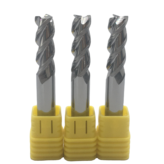
3-Flute Uncoated Square End Mill
35° helix and polished flutes for general aluminum milling.

3-Flute Polished Roughing End Mill
Serrated cutting edges for stock removal and chip control.

2-Flute Polished Micro End Mill
A micro-milling option; review tool reach, runout and the intended feature.

3-Flute DLC-Coated Square End Mill
An aluminum-specific DLC-coated option to review when adhesion and built-up edge are concerns.