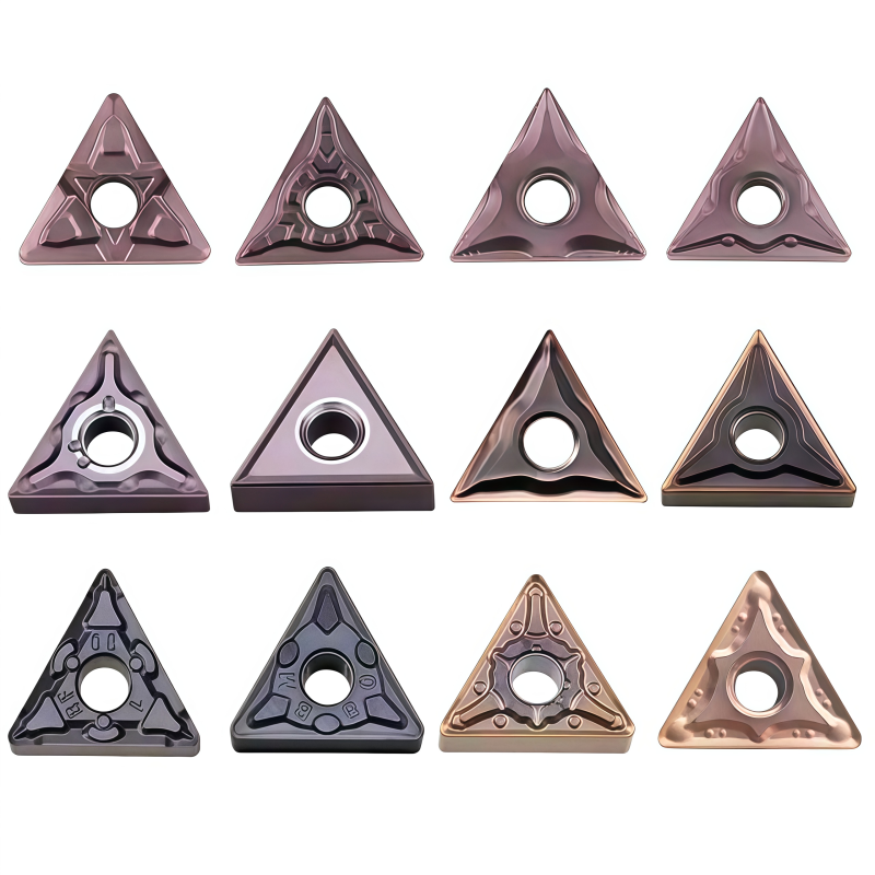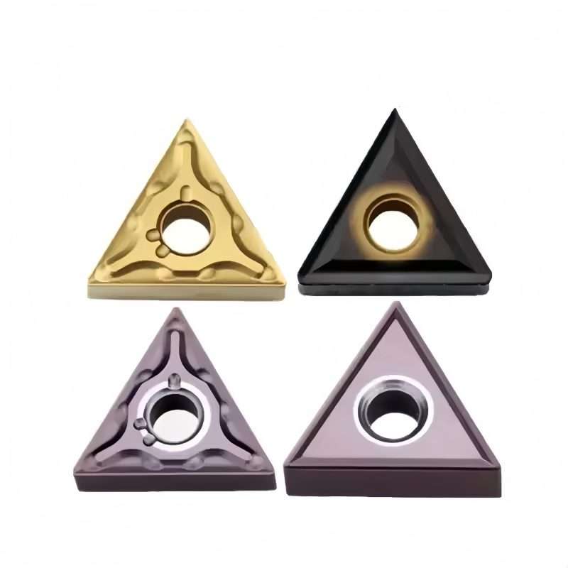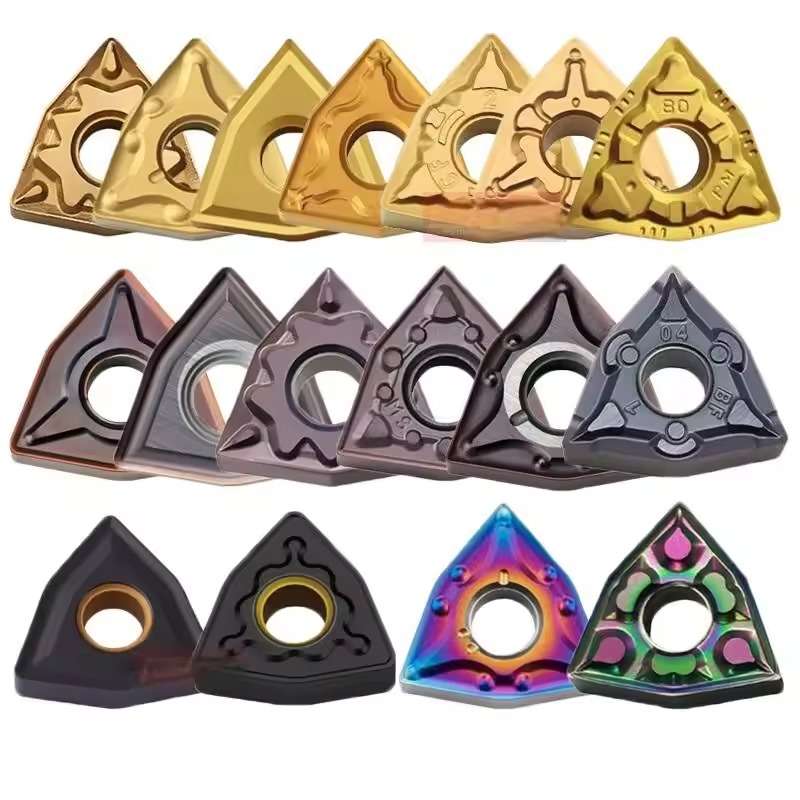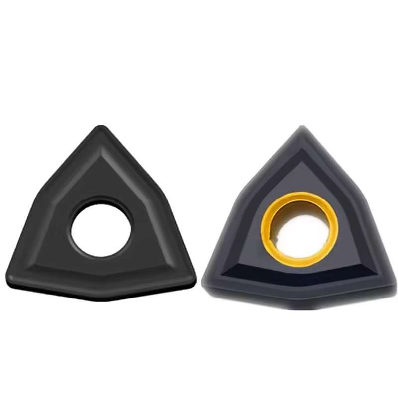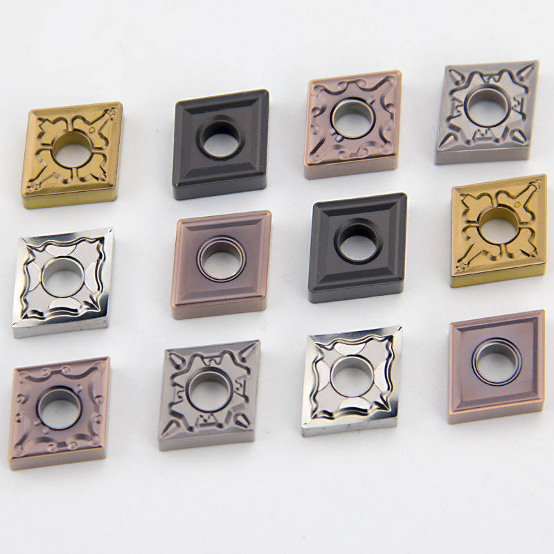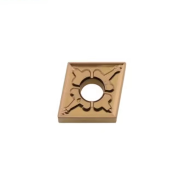
VNMG 1604 Carbide Turning Inserts for Steel and Stainless Steel
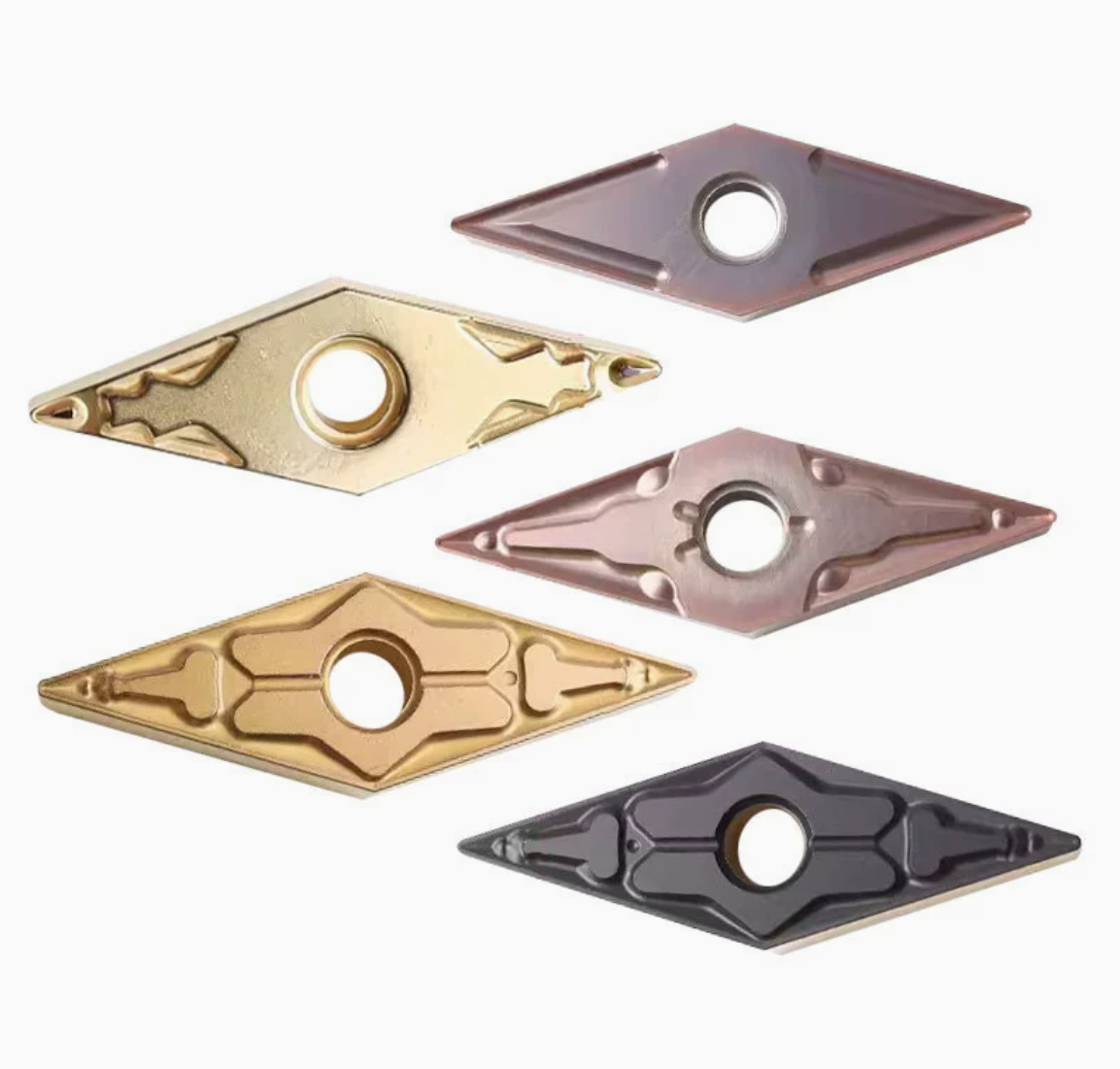
VNMG1604 carbide turning inserts feature a 35° diamond geometry for external turning, profiling and finishing of steel and stainless steel. Multiple corner radii, carbide grades, coatings and chipbreakers support precision machining in restricted-access areas while helping distributors cover different finishing and medium-cutting requirements.
Tutarlı Kalite
Tekrarlanan siparişlerde tutarlı geometri.
Esnek Siparişler
Küçük partiler ve farklı boyutlarda seçenekler mevcuttur.
OEM Desteği
Özel işaretleme, etiketler ve ambalajlama.
Standart ve Özel
Standart boyutlar ve özel konfigürasyonlar.
VNMG 1604 Series Overview
VNMG 1604 carbide turning inserts use a narrow 35° diamond geometry for external turning, facing, fine profiling and machining detailed component features. The pointed shape provides better access around shoulders, contours and restricted machining areas than wider insert geometries.
The series includes VNMG160404, VNMG160408 and VNMG160412, with grades and chipbreakers for steel and stainless steel. Customers building a broader CNC insert range can also view our carbide turning and milling inserts.
Models & Dimensions
Standard VNMG1604 dimensions are listed below. All dimensions are in millimeters.
| Model | Length L | I.C. | Thickness S | Hole Ød | Corner Radius r |
|---|---|---|---|---|---|
| VNMG160404 | 16.6 | 9.525 | 4.76 | 3.81 | 0.4 |
| VNMG160408 | 16.6 | 9.525 | 4.76 | 3.81 | 0.8 |
| VNMG160412 | 16.6 | 9.525 | 4.76 | 3.81 | 1.2 |
Selection note:
Smaller corner radii suit precision finishing and detailed profiling. Larger radii provide more edge strength but create higher radial cutting force. Confirm the holder, chipbreaker and machining allowance before ordering.
Chipbreaker Selection
| Model Group | Available Radius | Typical Positioning |
|---|---|---|
| VNMG160404/08-PMF | 0.4 / 0.8 mm | Finishing and light-to-medium turning with controlled chip formation. |
| VNMG160404/08-WM | 0.4 / 0.8 mm | General turning under stable and continuous machining conditions. |
| VNMG160404/08/12 | 0.4 / 0.8 / 1.2 mm | General-purpose coverage from finishing to heavier cutting. |
| VNMG-SF / MF | 0.4 / 0.8 mm | Sharp finishing geometries for stainless steel and selected alloys. |
| VNMG-FM / MM | 0.4 / 0.8 mm | Finishing-to-medium chip control with the appropriate grade. |
For a stronger 55° geometry with greater edge support, compare the DNMG 1504/1506 turning insert range.
Final chipbreaker selection should reflect the workpiece, feed, depth of cut and machining stability.
Grade Selection Guide
Steel · P
Stainless Steel · M
PVD · M / P
Grade-matching note:
Reference grades indicate approximate market positioning and are not guaranteed one-to-one equivalents. Trial cutting is recommended before volume replacement.
VNMG160404-PM Product Video
View the insert appearance, cutting-edge geometry and PM chipbreaker details before requesting samples or a quotation.
Application Guidance
Light turning where low cutting forces and profile accessibility are important.
The 35° point reaches detailed contours and restricted machining areas.
Smaller corner radii and sharp chipbreakers support controlled finishing and surface quality.
Because VNMG inserts have a narrow point, use appropriate feeds, depths of cut and stable clamping. For heavier machining, view the
WNMG 0804 turning insert series.
Customer Supply Support
VNMG160404, VNMG160408 and VNMG160412 with multiple chipbreakers.
Selected grades and chipbreakers can be combined according to the confirmed order quantity.
Neutral boxes, customer SKU labels, barcode labels and branded packaging are available by confirmation.
Product images, specifications and catalogue information can be supplied for customer sales use.
◆Specifications & Size Chart
The VNMG 1604 series uses a 35° diamond shape with 0° nominal relief and double-sided cutting geometry. The supplied product table lists three corner radii for external turning, facing and fine profiling. Dimensions below reproduce the supplied Overview; choose the complete grade and chipbreaker for the workpiece and operation.
| Model | Length L* | IC (D) | Thickness (S) | Hole (D1) | Corner Radius (rε) |
|---|---|---|---|---|---|
| VNMG 160404 | 16.6 mm | 9.525 mm | 4.76 mm | 3.81 mm | 0,4 mm |
| VNMG 160408 | 16.6 mm | 9.525 mm | 4.76 mm | 3.81 mm | 0,8 mm |
| VNMG 160412 | 16.6 mm | 9.525 mm | 4.76 mm | 3.81 mm | 1.2 mm |
◆Chipbreaker & Grade Selection
The Overview mentions PMF, WM, SF, MF, FM and MM chipbreaker styles. These suffixes are supplier-specific and do not establish identical geometry or cutting ranges across brands. Its product video shows a VNMG160404-PM example; confirm whether that exact PM configuration is offered for the grade you need.
| Overview Listing | Stated Positioning | Confirm for the Ordered Item |
|---|---|---|
| PMF / WM | Finishing to general turning | Available radius, workpiece grade, feed and depth-of-cut range. |
| SF / MF | Finishing, including selected stainless applications | Sharpness, edge preparation, chip flow and available grade. |
| FM / MM | Finishing to medium turning | Exact chipbreaker drawing, material group and chip-control window. |
| YC331 / YP731 / YP753 | Overview grade examples for P and M applications | Which full model and chipbreaker is supplied in each grade, coating data and cutting recommendation. |
◆How to Select a VNMG 1604 Insert
For additional guidance, use the CNC Insert Selection Guide.
◆Starting Cutting Data
There is no single safe speed, feed or depth-of-cut range for every VNMG 1604 grade and chipbreaker. Obtain the cutting data for the complete insert code and exact workpiece grade. For turning, n = (1000 × Vc) / (π × D), where n is RPM, Vc is cutting speed in m/min and D is workpiece diameter at the cut in mm. Compare the proposed feed with the chipbreaker's operating window.
◆Related Series & Technical References
For a broader insert selection, see our carbide turning and milling insert range. Compare a DNMG 1504/1506 series when a 55° corner better fits the job.
For the current VNMG drawing, grade sheet, chipbreaker data or quotation, send the full insert and holder codes with your workpiece and quantity.
◆Carbide Insert Customization & OEM
Specify the insert around the machining operation, workpiece and holder. We can review standard replacements, application-specific geometry and private-label requirements using your insert designation, drawing or sample. Available grades, coatings, dimensions and order quantities are confirmed for each requested series.
Geometry & Chip Control
Review chipbreaker, rake, cutting-edge preparation, nose radius and corner design for the operation and workpiece. Confirm holder compatibility before approving a modified geometry.
Substrate & Coating
Select an available carbide grade and coating for the workpiece material, cutting conditions and desired balance of wear resistance and edge toughness.
Dimensions & OEM
Review insert size, thickness, locating and clamping features, tolerances, laser marking and private-label packaging against the approved specification.
◆Customization Options
Use the fields below when sending an inquiry. The exact options depend on the insert family and are confirmed in the quotation or approved drawing.
| Şartname | Details to Confirm |
|---|---|
| Ekleme Tipi | Turning, milling, threading, grooving or drilling insert; send the designation or drawing. |
| Size & Fit | Shape, size, thickness, inscribed circle or edge length, hole or clamping form, and holder model. |
| Kesim Geometrisi | Chipbreaker, nose or corner radius, edge preparation, cutting direction and application-specific profile. |
| Grade & Coating | Workpiece group and grade, carbide substrate, coating system and wet or dry cutting conditions. |
| Tolerance & Inspection | Critical dimensions, profile requirements, inspection method and any required report. |
| OEM Presentation | Insert or box marking, label content, packaging format and quantity per pack. |
◆How to Request a Custom Insert

Send your insert requirements through our contact form or review our OEM and private-label service.
◆Carbide Insert Quality Control

Insert quality depends on the approved grade, geometry, coating and dimensional specification. We review the requirements at order confirmation and align the inspection scope with the insert series and any customer drawing. Share critical dimensions or documentation needs before production so they can be included in the agreed inspection plan.
01 · Incoming Material
Confirm the specified carbide grade or material documentation against the order requirements.
02 · In-Process Checks
Review dimensions and cutting-edge features during production against the approved specification.
03 · Final Inspection
Check the agreed dimensions, appearance, edge condition, coating identification and marking as applicable.
04 · Packing Review
Verify the item code, quantity, labels and protective packing against the approved order.
◆Inspection & Documentation
Inspection points and acceptance criteria should be agreed for the ordered series. For custom inserts, the approved drawing takes priority over a generic catalogue description.
| Check Area | What to Confirm |
|---|---|
| Dimensions & Fit | Insert size, thickness, corner radius, clamping features and any drawing tolerances. |
| Kesim Geometrisi | Chipbreaker, edge preparation, usable corners and profile where applicable. |
| Grade & Coating | Approved grade and coating designation; any requested verification method. |
| Appearance & Packing | Visible edge damage, marking, item code, count and packing format. |
| Requested Records | Inspection report, material or coating documentation, sample approval or batch identification when agreed. |
◆Order & Delivery
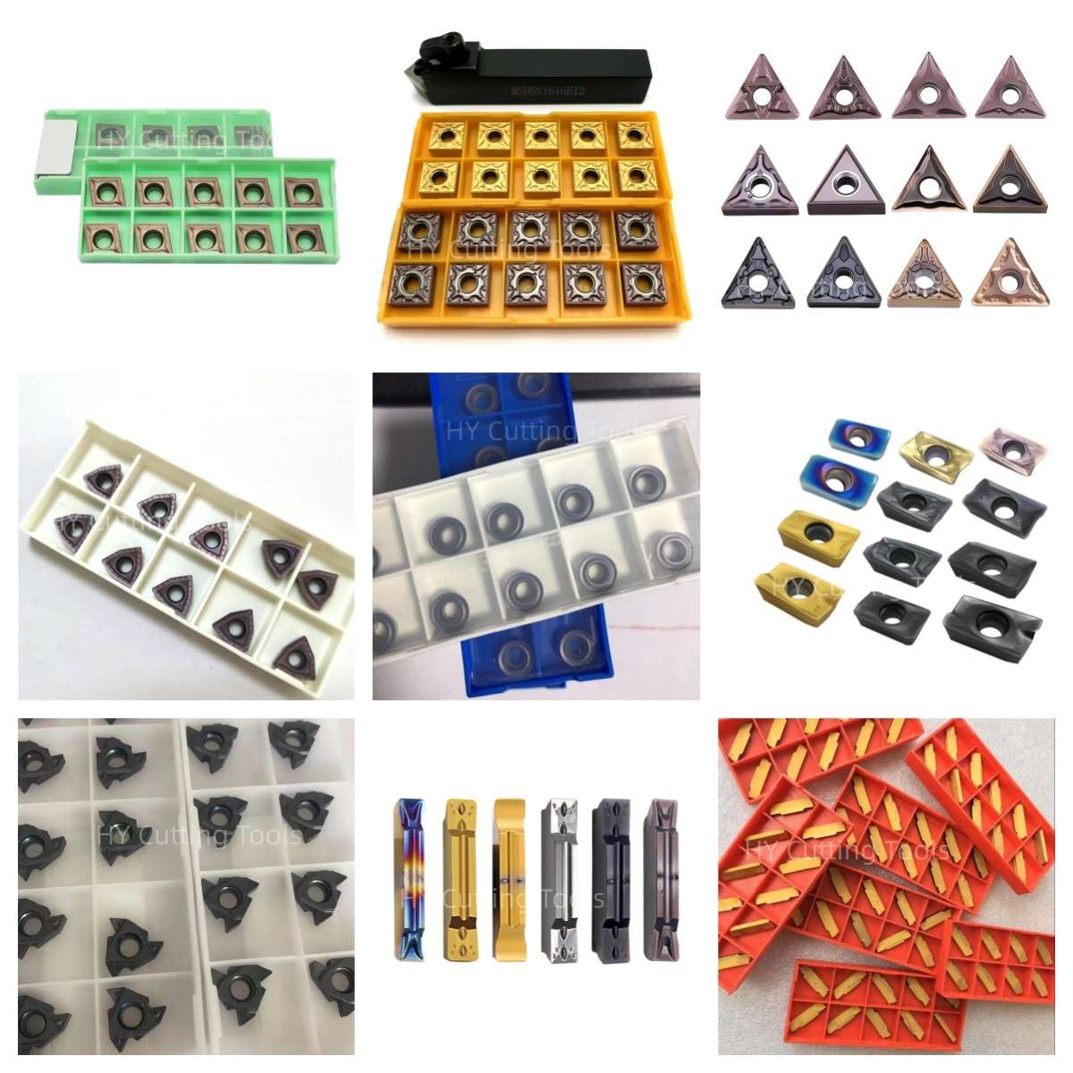

Share a line-by-line list of insert codes and quantities for a mixed-size quotation. Stock status, minimum quantity, sample requirements and production lead time are confirmed for each grade, coating and configuration.
Send your item list and quality requirements through our contact form for specification, availability and delivery confirmation.
◆Product FAQs
What is a VNMG 1604 insert used for?
Its 35° diamond point provides access for external turning, fine profiling and detailed contours with a compatible tool holder. Facing depends on the holder's approach angle and workpiece clearance. The narrow point is best selected for a suitable feed and depth of cut rather than assumed to suit heavy interrupted machining.
What changes between VNMG 160404, 160408 and 160412?
The supplied dimensions list the same VNMG 1604 body and nominal corner radii of 0.4, 0.8 and 1.2 mm. Smaller radii help access fine details and may reduce radial force. A larger radius supports the corner at suitable feed but needs more clearance and a rigid setup. Check the actual chipbreaker and finished-profile requirement.
Are the VNMG 1604 dimensions the same as cutting-edge length?
No. The supplied Overview labels 16.6 mm as Length L. Effective cutting-edge length may be defined differently in manufacturer catalogues and vary by corner radius or chipbreaker. Confirm the dimension definitions in the current drawing before comparing two brands.
Can the same VNMG insert machine both steel and stainless steel?
The page covers grades for both material groups, but a size code alone does not establish dual-material suitability. Specify the exact steel or stainless grade and hardness, then confirm the matching carbide grade, coating and chipbreaker for that workpiece and cut.
How do I choose between PMF, WM, SF, MF, FM and MM?
These are chipbreaker designations mentioned in the Overview, not universal geometry standards. Send your workpiece, holder, feed, depth of cut, coolant and chip-control problem. Confirm which suffix and grade combination is available for the selected corner radius and obtain its operating window.
How does VNMG differ from DNMG or WNMG?
VNMG has a 35° diamond corner suited to detailed profile access. DNMG uses a 55° diamond and WNMG an 80° trigon, which can provide more corner support where the part geometry allows. The actual holder, grade, chipbreaker and cutting conditions still govern selection.
◆Ordering & OEM FAQs
What should I send for a VNMG replacement request?
Provide the complete insert code, original manufacturer, grade and chipbreaker, box-label and insert photos, holder model, workpiece material, cutting parameters and required quantity. Check a proposed replacement for seat fit and machining performance before production use.
Are YC331, YP731 and YP753 direct equivalents to the reference grades?
No one-to-one equivalence is established by the Overview. Compare the supplier grade sheets, coating and application ranges, then conduct a controlled cut to assess chip control, tool wear, surface finish and cost per accepted part.
Can I combine different models and grades in one order?
The Overview offers mixed-model supply by confirmation. Send each full VNMG model, chipbreaker, grade and quantity as a separate line. Stock, minimum order quantity, packaging and delivery time are confirmed per item.
Can I request private-label packaging and product information?
The Overview lists neutral or branded boxes, customer SKU and barcode labels, plus product images and specifications for sales use. Send artwork, label details, item list and forecast quantity so the available options and lead time can be confirmed.
◆Guides & Technical References
Use the CNC Insert Selection Guide for shape, grade, nose-radius and chipbreaker checks. The Carbide Insert Types Guide explains related insert families.
For the current VNMG 1604 drawing, grade data or quotation, send the complete insert and holder codes with your workpiece and required quantity.
Ölçüler, fiyatlar veya özel seçenekler mi arıyorsunuz?
Gerekli takım türünü, boyutlarını, miktarlarını, iş parçası malzemesini ve varsa OEM veya özel gereksinimleri bize iletin. Uygun teknik özellikleri, stok durumunu, teslim süresini ve fiyat teklifi ayrıntılarını size teyit edeceğiz.
Çizimler, boyut listeleri ve referans fotoğraflar memnuniyetle kabul edilir.