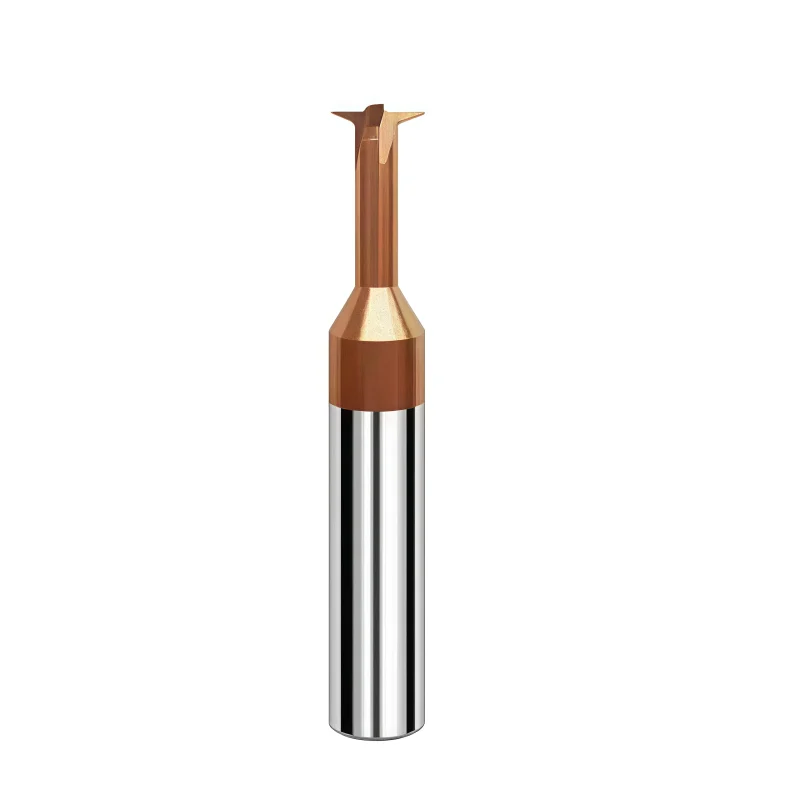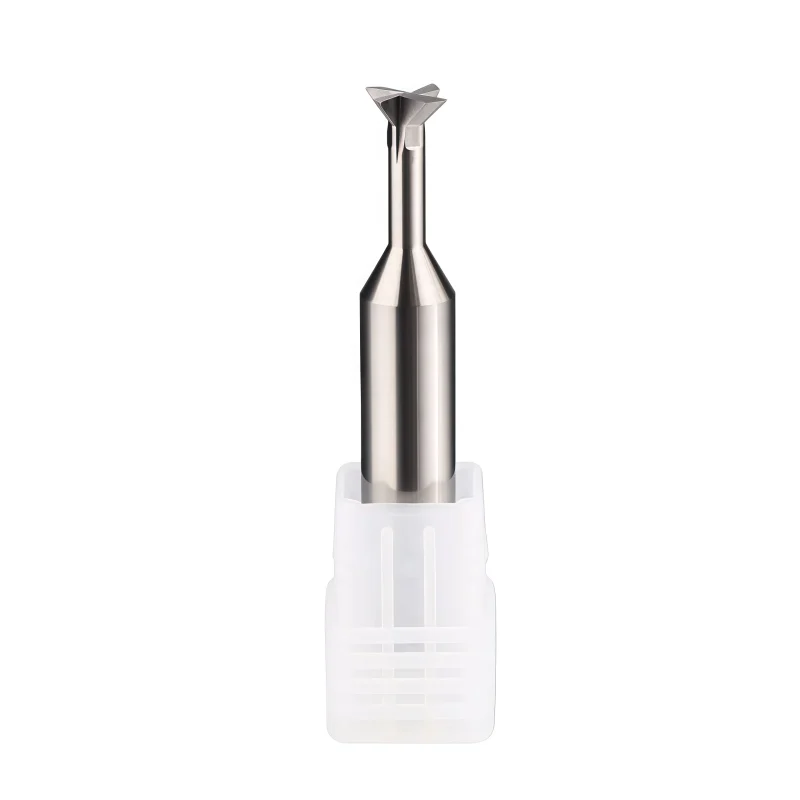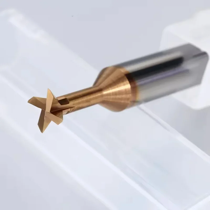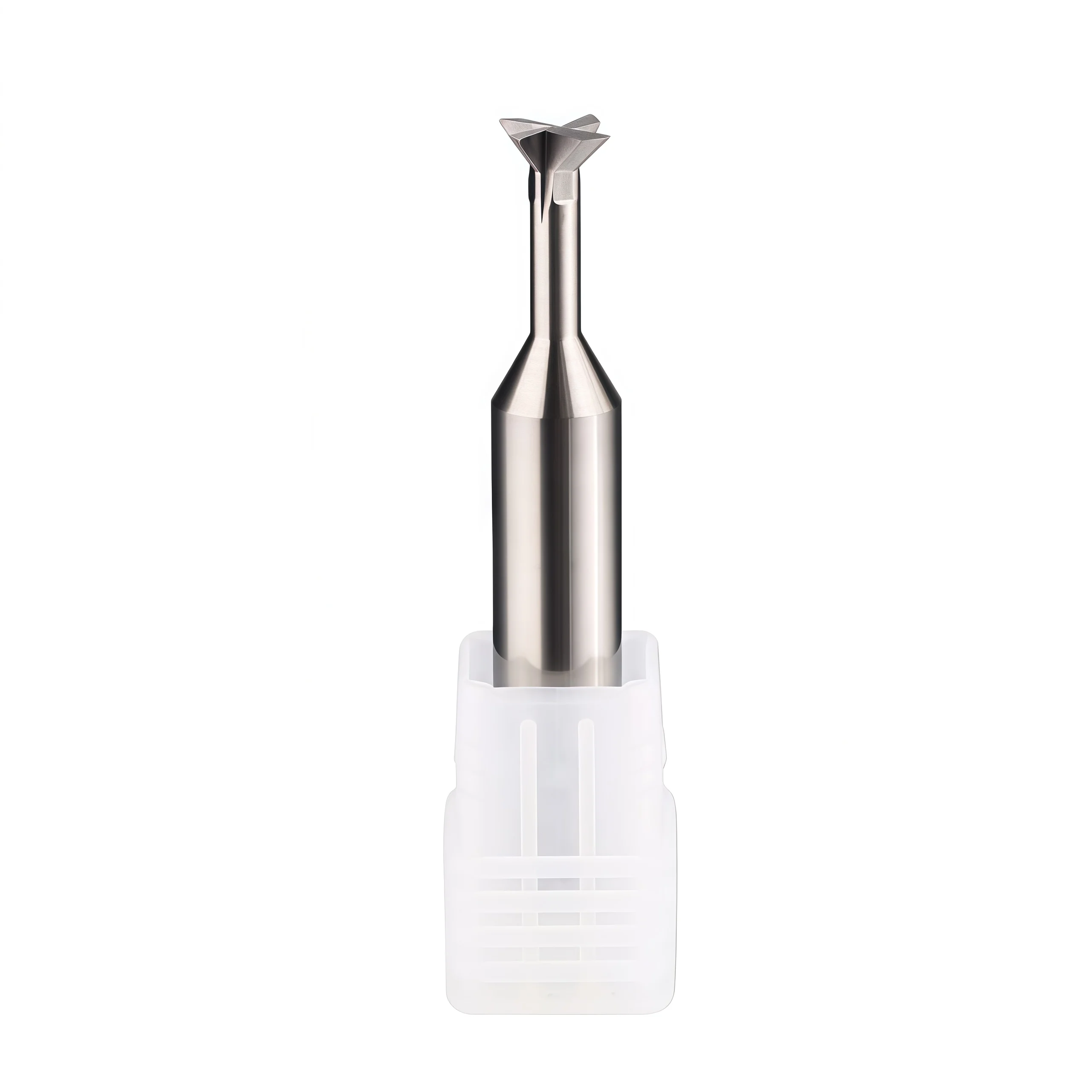
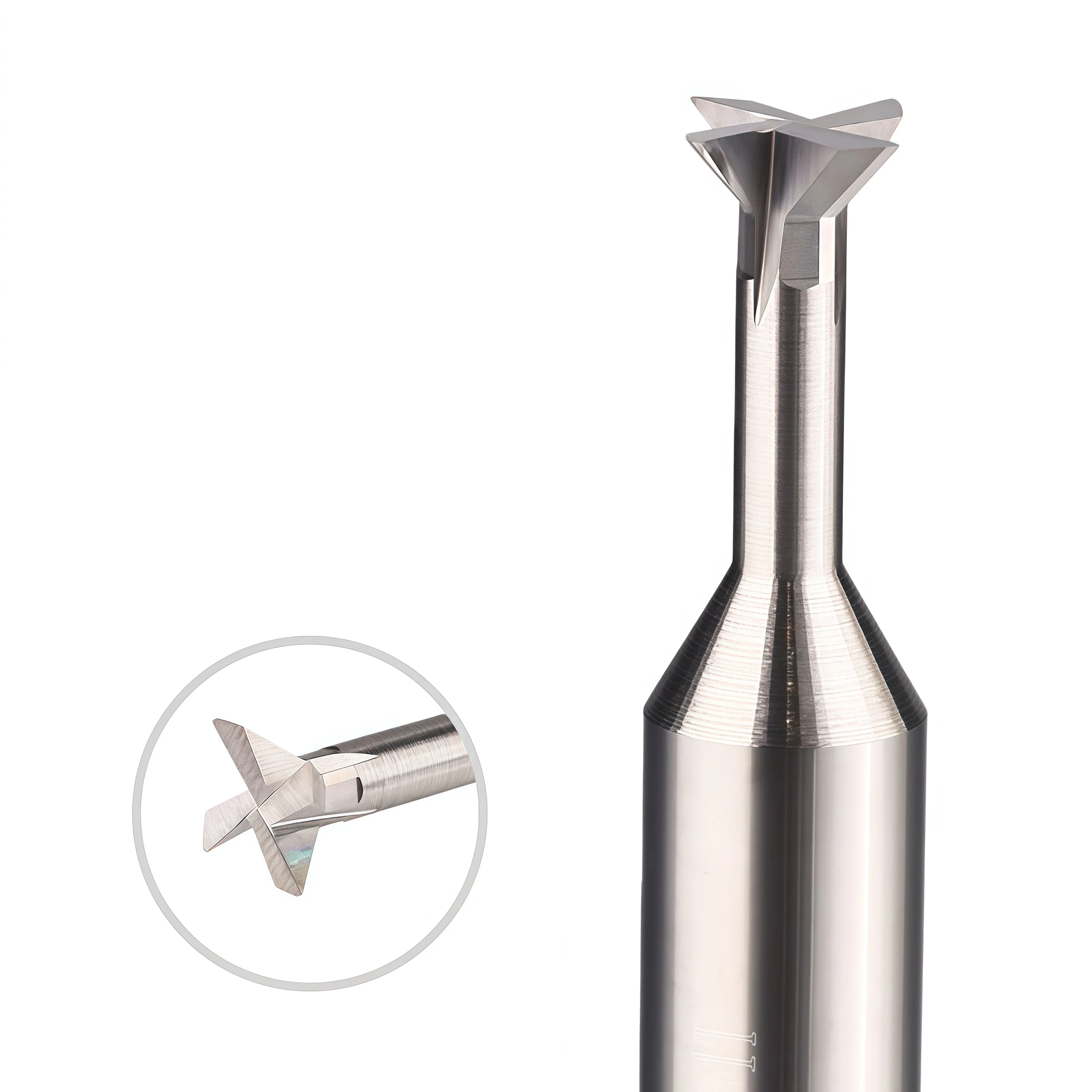
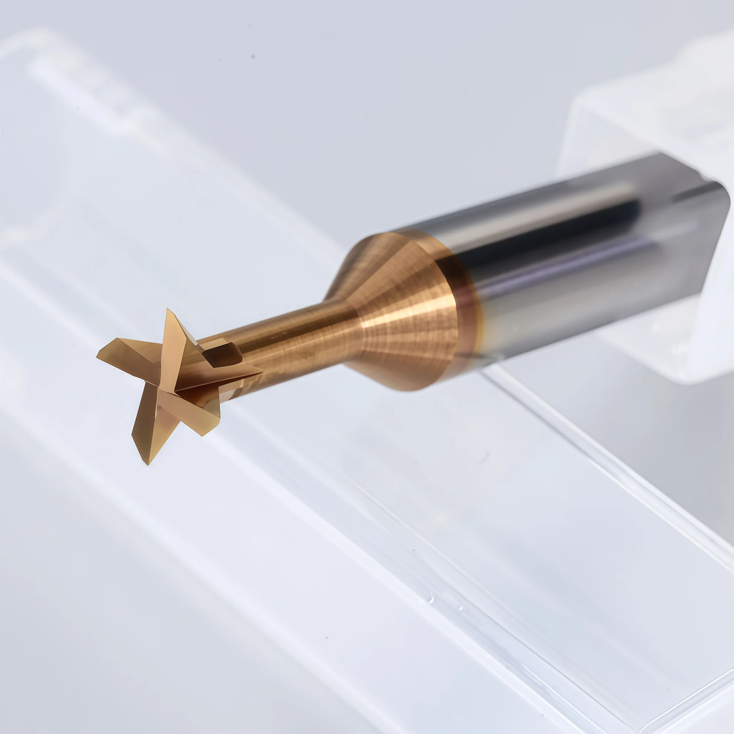
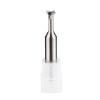
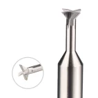

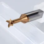
4-Flute Solid Carbide Dovetail Cutter for Slot Milling
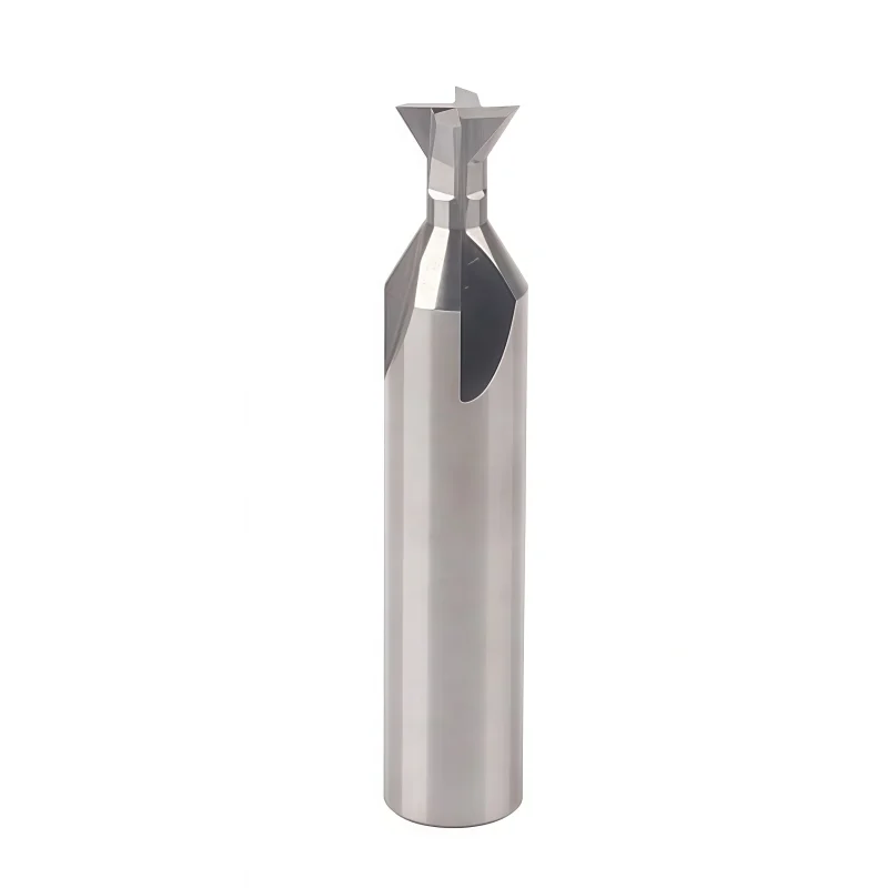
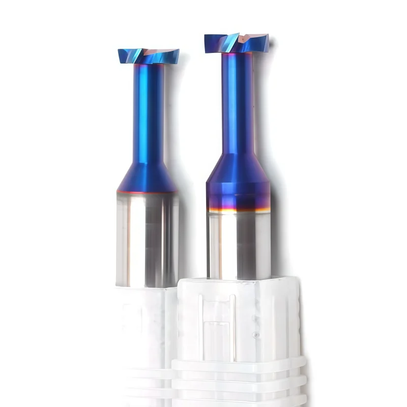
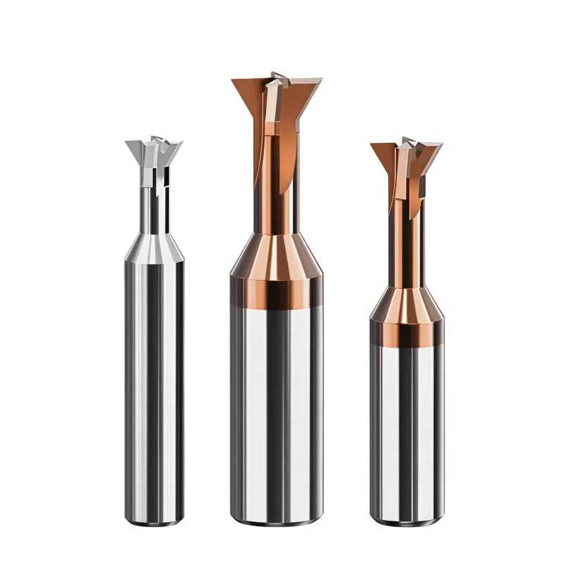
4-flute solid carbide dovetail cutter for dovetail slot milling, angled undercutting, guide grooves and locking-profile machining. The formed cutting geometry provides access to recessed angled features, while standard 45° and custom configurations can be selected according to the required slot profile, workpiece material and machining depth.
- ◆4-flute solid carbide structure provides repeated cutting-edge engagement for stable profile milling
- ◆Formed dovetail geometry is designed for angled grooves, undercuts, guideways and locking features
- ◆Standard 45° reference sizes and drawing-defined custom profiles are available for different slot requirements
Consistent Quality
Consistent geometry across repeat orders.
คำสั่งซื้อที่ยืดหยุ่น
Small batches and mixed sizes available.
OEM Support
Custom marking, labels and packaging.
แบบมาตรฐานและแบบตามสั่ง
Standard sizes and custom configurations.
4-Flute Solid Carbide Dovetail Cutter Overview
This 4-flute solid carbide dovetail cutter is designed for dovetail slot milling, angled undercutting, guide grooves and locking features in CNC-machined components. The formed cutting profile allows angled sidewalls to be produced below an access opening, while the four-flute solid carbide structure provides repeated cutting-edge engagement during profile milling. Standard 45° reference sizes are available, while non-standard diameters, profile angles, neck dimensions and overall lengths can be reviewed according to the component drawing and machining requirements.
Dovetail Cutter
4 Flutes
45° Series
Solid Carbide
Dovetail Slot-Milling Geometry
Formed Dovetail Profile
The angled cutting profile is used to machine dovetail grooves, guideways, retaining features and mechanical locking profiles.
4-Flute Cutting Structure
Four cutting edges provide repeated engagement during side-profile milling and support controlled cutting when machine rigidity, runout and chip evacuation are properly managed.
Reduced-Neck Access
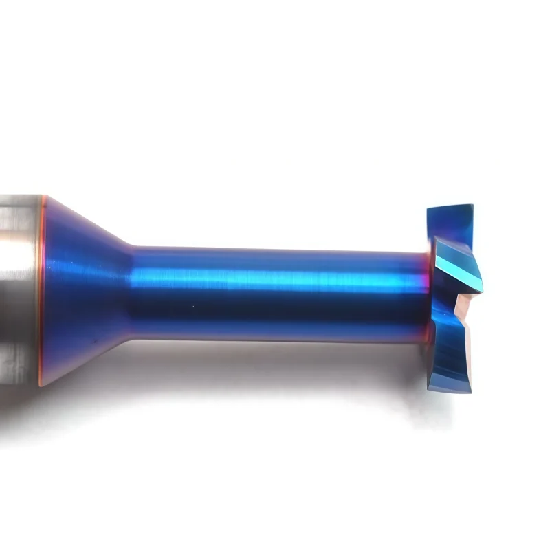
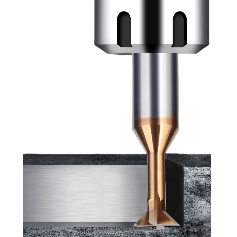
The necked geometry provides access behind the slot opening so the formed cutting edges can reach angled undercut surfaces.
Application-Specific Advantages
Defined Profile
Standard 45° reference geometry for common dovetail and locking-slot applications.
Four Cutting Edges
Four-flute design provides frequent edge engagement during profile milling.
Undercut Access
Suitable for angled features located below an existing access slot or opening.
Custom Geometry
Profile angle, diameter, neck geometry and overall dimensions can be reviewed from drawings.
Recommended Machining Operations
RECOMMENDED
RECOMMENDED
RECOMMENDED
SUITABLE
Workpiece Material Configuration
| WORKPIECE GROUP | CONFIGURATION GUIDANCE | SELECTION FOCUS |
|---|---|---|
| PCarbon & Alloy Steel | AlTiN / TiAlN according to cutting conditions | Heat resistance, edge strength and chip control |
| MStainless Steel | Coating and rake geometry selected for the alloy | Controlled cutting load and reduced work hardening |
| NAluminum & Non-Ferrous | Polished uncoated or suitable low-friction configuration | Sharp edge, chip clearance and reduced material adhesion |
Recommended Dovetail Milling Sequence
Prepare the Access Slot
Use a suitable straight-sided cutter to remove the central material and create sufficient access for the dovetail cutter.
Mill the Dovetail Profile
Engage the dovetail cutter with controlled side contact and avoid unnecessary full-profile loading.
Verify the Finished Feature
Check groove width, profile angle, undercut depth and mating fit before releasing the production process.
Product Details
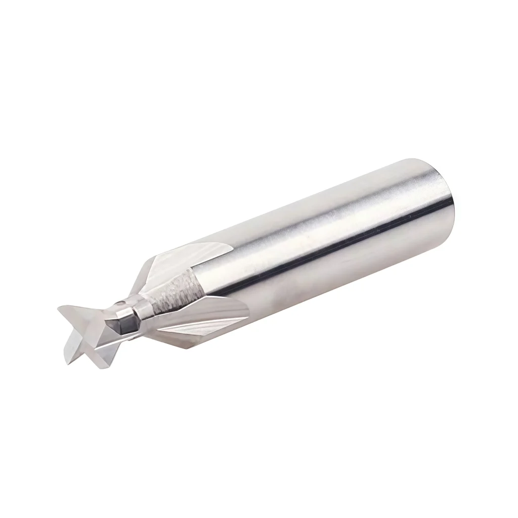


Dovetail Cutter Nomenclature & Dimensions
The dovetail cutter should be selected according to cutting diameter, shank diameter, overall length, profile angle, neck clearance and the finished slot geometry. The current documented standard-reference series uses a 45° dovetail profile.
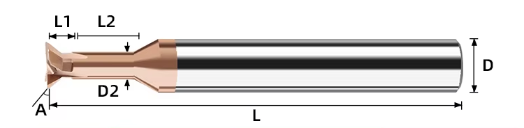
Technical Configuration
| PARAMETER | REFERENCE CONFIGURATION |
|---|---|
| Tool Type | Solid Carbide Dovetail Cutter |
| Tool Material | Solid Carbide |
| Flute Count | 4 Flutes |
| Reference Dovetail Angle | 45° in the documented standard series |
| Cutting Diameter D1 | 1.5–12 mm in the current documented reference matrix |
| Shank Diameter D2 | 4–12 mm in the current documented reference matrix |
| Overall Length L | 50 mm / 60 mm in the current standard-reference matrix |
| Material Configuration | Carbon & Alloy Steel / Stainless Steel / Aluminum & Non-Ferrous |
| Surface / Coating Selection | Selected according to workpiece material; AlTiN / TiAlN referenced for steel, polished uncoated or suitable low-friction configuration for aluminum |
| Primary Operations | Dovetail Slot Milling / Angled Undercutting / Guideway Milling / Locking Grooves / Recessed Profiling |
| Customization | Cutting diameter, shank diameter, profile angle, neck geometry, reach, overall length, edge preparation, coating, marking and packaging |
45° Reference Size Matrix
Current documented reference sizes for the 4-flute solid carbide dovetail cutter series. All dimensions are in millimeters.
| SPECIFICATION | D1 | D2 | L | ANGLE |
|---|---|---|---|---|
| D1.5 × 45° × D4 × 50L | 1.5 | 4 | 50 | 45° |
| D2.0 × 45° × D4 × 50L | 2.0 | 4 | 50 | 45° |
| D2.5 × 45° × D4 × 50L | 2.5 | 4 | 50 | 45° |
| D3.0 × 45° × D4 × 50L | 3.0 | 4 | 50 | 45° |
| D4.0 × 45° × D4 × 50L | 4.0 | 4 | 50 | 45° |
| D5.0 × 45° × D5 × 50L | 5.0 | 5 | 50 | 45° |
| D6.0 × 45° × D6 × 50L | 6.0 | 6 | 50 | 45° |
| D8.0 × 45° × D8 × 50L | 8.0 | 8 | 50 | 45° |
| D10.0 × 45° × D10 × 60L | 10.0 | 10 | 60 | 45° |
| D12.0 × 45° × D12 × 60L | 12.0 | 12 | 60 | 45° |
Dovetail Slot-Milling Guidance
- Prepare Clearance First: For many dovetail applications, remove the central slot material with a suitable straight-sided cutter before engaging the formed dovetail profile.
- Entry Clearance: Confirm sufficient opening width and neck clearance before the dovetail cutter enters the undercut region.
- Controlled Side Engagement: Avoid unnecessary full-width form loading and use a stable toolpath when finishing angled sidewalls.
- Material Matching: Select cutting-edge preparation and coating according to the actual workpiece material rather than using one configuration universally.
- Deep Features: For deeper grooves, machine progressively and verify that neck clearance and tool rigidity are sufficient.
- Custom Profiles: Provide the component drawing when profile angle, neck diameter, reach or finished slot dimensions differ from the standard 45° series.
4-Flute Solid Carbide Dovetail Cutter Customization
Cutting diameter, shank diameter, dovetail angle, neck clearance, overall length, cutting-edge preparation and coating can be configured for dovetail slot milling and undercutting applications. Standard configurations use a 4-flute solid carbide cutting structure with a documented 45° dovetail profile, while non-standard dimensions and alternative profile requirements can be reviewed according to the workpiece material, groove geometry, machining depth, available clearance and required dimensional accuracy.
| PARAMETER | MANUFACTURING CAPABILITIES |
|---|---|
| Dovetail Angle | 45° is the documented standard-reference profile for this series. Alternative dovetail angles can be reviewed according to the required groove geometry and component drawing. |
| Cutting Diameter (D1) | The current reference matrix covers D1 sizes from 1.5 mm to 12 mm. Non-standard cutting diameters can be reviewed according to the required dovetail profile and available entry clearance. |
| Shank Diameter (D2) | The documented standard-reference series uses D2 sizes from 4 mm to 12 mm, with drawing-defined shank dimensions reviewed for custom toolholding requirements. |
| Flute Count | Standard 4-flute solid carbide configuration for dovetail slot milling, angled undercutting, guide grooves and locking-profile machining. |
| Neck & Undercut Clearance | Neck diameter, neck length and relief geometry can be reviewed according to groove depth, undercut width, adjacent-wall clearance and required machining reach. |
| Overall Length | The current standard-reference matrix uses 50 mm and 60 mm overall lengths. Custom lengths can be reviewed according to machining depth, holder clearance and tool-rigidity requirements. |
| Dovetail Profile Geometry | Profile geometry can be matched to the required dovetail groove width, side angle, undercut depth and mating feature, with drawing-defined dimensions available for non-standard tools. |
| Cutting-Edge Preparation | Edge preparation and relief geometry can be reviewed according to workpiece material, cutting load, chip formation and required surface condition. |
| Coating & Surface Selection | AlTiN or TiAlN configurations can be reviewed for carbon and alloy steel, while stainless steel and aluminum require material-specific coating, surface finish and edge preparation. |
| Workpiece Material | Configurations can be reviewed for carbon and alloy steel, stainless steel, aluminum and compatible non-ferrous materials according to the selected geometry and surface treatment. |
| Machining Application | Geometry can be reviewed for dovetail slot milling, angled undercutting, guideways, retaining grooves, locking features and recessed-profile machining. |
| Entry & Access Geometry | Cutter diameter, neck geometry and undercut reach should be matched to the pre-machined access slot and available component clearance before final tool selection. |
| Dimensional Tolerance | Drawing-defined requirements can be reviewed for D1, D2, dovetail angle, neck diameter, neck length, overall length and finished profile dimensions. |
| Replacement Tool Matching | Existing dovetail cutters can be reviewed from a detailed tool drawing, component drawing or physical sample when an equivalent replacement profile is required. |
| OEM & Private Label | Laser marking, custom tool codes, private labels and packaging can be reviewed for distributors, tooling brands and OEM customers. |
บริการ OEM และแบรนด์ส่วนตัว
OEM manufacturing and private-label supply options are available for industrial distributors, tooling brands and repeat-production customers. Laser identification, label content, protective packaging and coating presentation can be configured according to the approved product specification and order requirements.

Laser Etching
Custom logos, tool codes, cutting dimensions, coating identification and batch numbers can be marked according to the available shank area.
Custom Labels & Packaging
Individual protective tubes, product labels, specification details, colored packaging tubes and private-label packaging can be reviewed.
Commercial Terms
MOQ, sample evaluation, custom-size trials, repeat orders and scheduled supply programs are confirmed according to the selected configuration.
Technical Workflow
A structured review process is used to confirm standard, customized and private-label square end mill requirements before production.
Inquiry
Submit the material, hardness, milling operation, dimensions, tolerance and quantity.
Engineering
Review flute geometry, helix angle, edge preparation, coating, ap and ae.
Commercial
Confirm quotation, MOQ, sample requirements, production schedule and delivery terms.
Production
CNC grinding, end-face formation, edge preparation, coating and laser marking.
Quality Control
Inspect diameter, flute length, shank, runout, square-end geometry and cutting edges.
Quality, Inspection & Delivery
Our solid carbide square end mills are controlled through material verification, precision grinding, in-process measurement and final inspection. Key dimensions, square-end geometry, cutting-edge condition, coating appearance and product identification are reviewed according to the approved specification or drawing before packing.

Three-Stage Quality Control
Inspection checkpoints are arranged around the manufacturing process to support dimensional consistency and repeat-order control.
Incoming Material Control
Carbide substrate grade, blank dimensions and supplied material information are checked against the production requirement.
In-Process Grinding Control
Cutting diameter, flute geometry, flute length, square-end profile and shank dimensions are monitored during CNC grinding.
Final Tool Inspection
Finished tools are reviewed for specified dimensions, runout, cutting-edge condition, coating appearance, marking and packing identification.
Key Inspection Characteristics
Inspection requirements are confirmed according to the standard product specification or the approved custom drawing.
| INSPECTION ITEM | CONTROL FOCUS | CONFIRMATION BASIS |
|---|---|---|
| Cutting Diameter (DC) | Diameter and dimensional consistency | Standard specification or approved drawing |
| Flute Length (APMX) | Effective cutting length | Confirmed product size or drawing requirement |
| Shank Diameter (DCON) | Clamping-section dimension and surface condition | Applicable shank specification |
| Overall Length (OAL) | Total tool length | Standard size matrix or approved drawing |
| Radial Runout | Concentricity between cutting section and shank | Agreed inspection requirement |
| Square-End Geometry | End-face profile, corner condition and center-cutting form | Selected tool configuration |
| Flute & Helix Profile | Flute count, helix form and grinding consistency | Approved manufacturing configuration |
| Cutting Edge & Coating | Edge condition, visible defects and coating appearance | Application-specific production requirement |
| Marking & Identification | Tool code, dimensions and batch information where applicable | Confirmed order and packaging specification |
Measurement & Batch Traceability
Optical measuring systems, tool inspection equipment and appropriate dimensional gauges are selected according to the feature being checked.
Optical Measurement
Profile and dimensional review of specified cutting features.
Runout Verification
Concentricity review based on the agreed product requirement.
Edge Inspection
Magnified review of the end face, corners and cutting-edge condition.
Batch Identification
Order, product and batch information are linked where required for repeat supply.
Protective Packaging Process
Finished end mills are protected to reduce contact between cutting edges and to support clear product identification during storage and transportation.

Bulk-Order & Export Packaging
Bulk shipments can be arranged with reinforced cartons, protective wrapping, palletized loading or export cases according to order quantity, shipment weight and agreed transportation requirements.

Delivery Coordination
Production completion, packing method and dispatch arrangements are confirmed according to the approved order. Courier, air, sea or customer-designated shipping options can be reviewed according to shipment size and destination. Final lead time is confirmed after product specifications, quantity and packaging requirements are approved.
Product & Application FAQs
Common questions about the 4-flute solid carbide dovetail cutter for dovetail slot milling, angled undercutting and recessed-profile machining.
What is this 4-flute dovetail cutter designed for?
What is the standard dovetail angle?
Why use a 4-flute dovetail cutter?
Should the access slot be machined before using the dovetail cutter?
Which materials can be machined?
Which coating or surface configuration should be selected?
Can the cutter be used for deep dovetail grooves?
Ordering & Customization FAQs
Ordering information for distributors, tooling suppliers and OEM customers requiring standard or non-standard dovetail cutters.
Can the dovetail angle be customized?
Can diameter, neck dimensions and overall length be customized?
Can you manufacture a replacement dovetail cutter from a drawing?
Are OEM marking and private-label packaging available?
ระยะเวลาการผลิตโดยทั่วไปคือเท่าไร?
What information should I provide for quotation?
Technical Downloads
Reference documents for solid carbide milling cutter selection and machining-data review.
Solid Carbide End Mill Catalog
Review dovetail cutters and related specialty solid carbide milling tools.
End Mill Speeds & Feeds Guide
Use as a general reference before confirming final dovetail slot-milling parameters.
Need Sizes, Pricing or Custom Options?
Send us the required tool type, sizes, quantities, workpiece material and any OEM or custom requirements. We will confirm suitable specifications, availability, lead time and quotation details.
Drawings, size lists and reference photos are welcome.