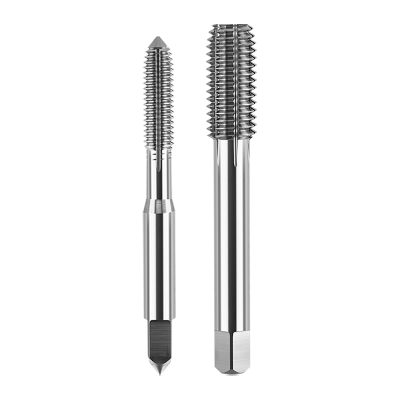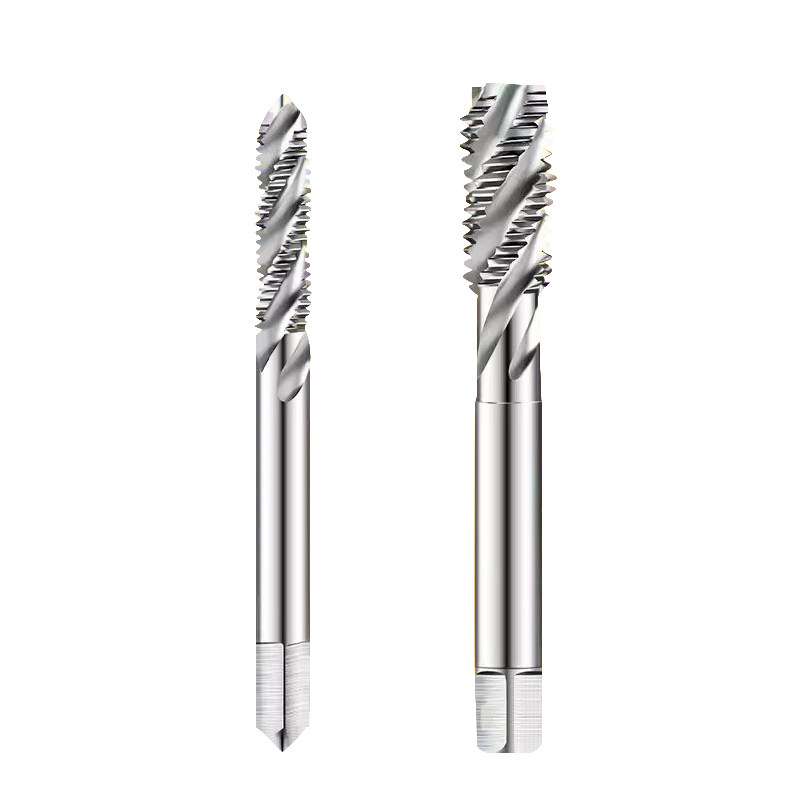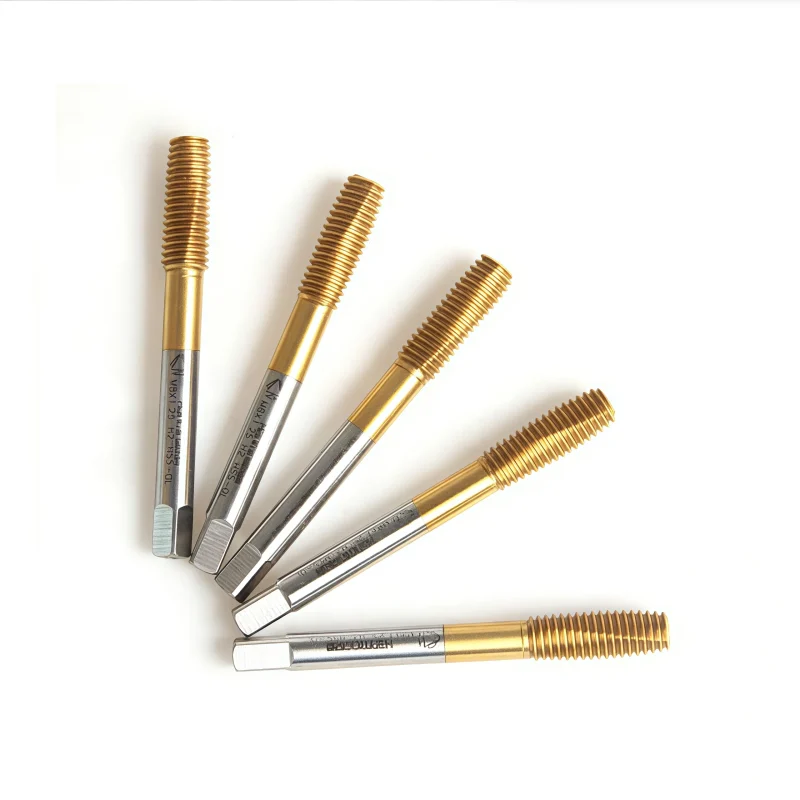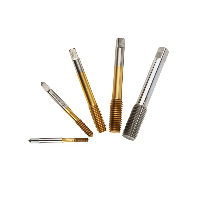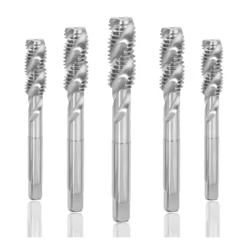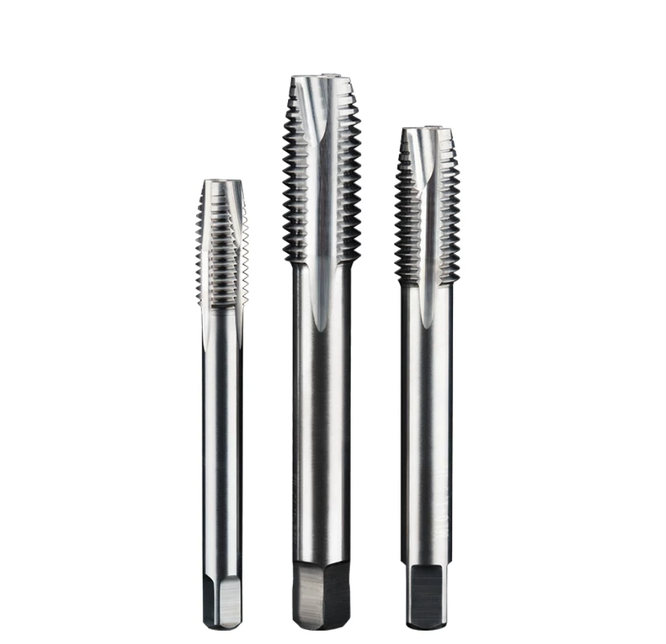
Solid Carbide Spiral Point Machine Tap for Through Holes
Product Specifications
10 Pieces per Size
1–3 Days for In-Stock Sizes
Dimensions / Thread Tolerance / Coating / OEM
Consistent Quality
Consistent geometry across repeat orders.
Гибкие заказы
Small batches and mixed sizes available.
OEM Support
Custom marking, labels and packaging.
Стандартные и индивидуальные
Standard sizes and custom configurations.
Solid Carbide Spiral Point Tap Overview
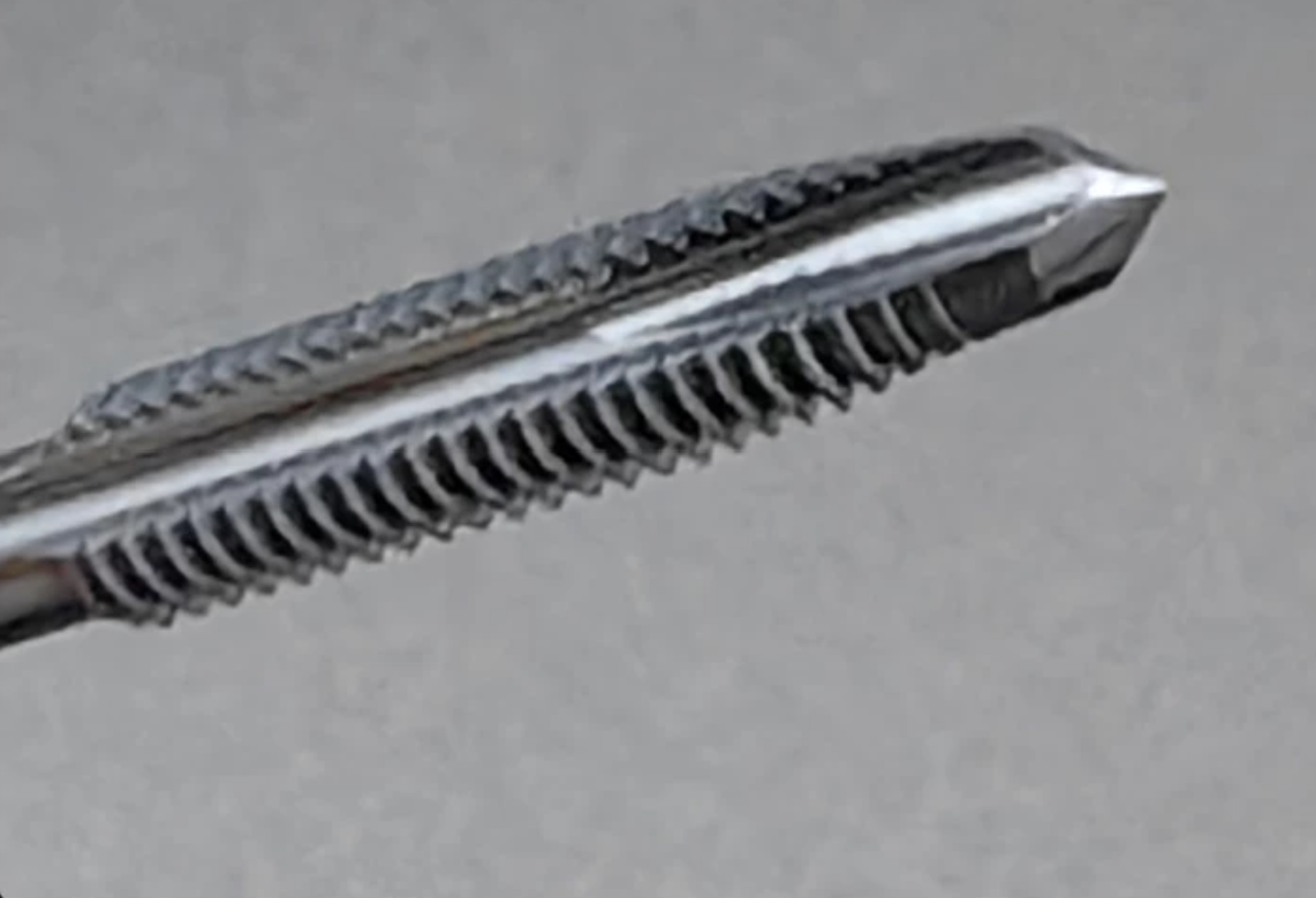
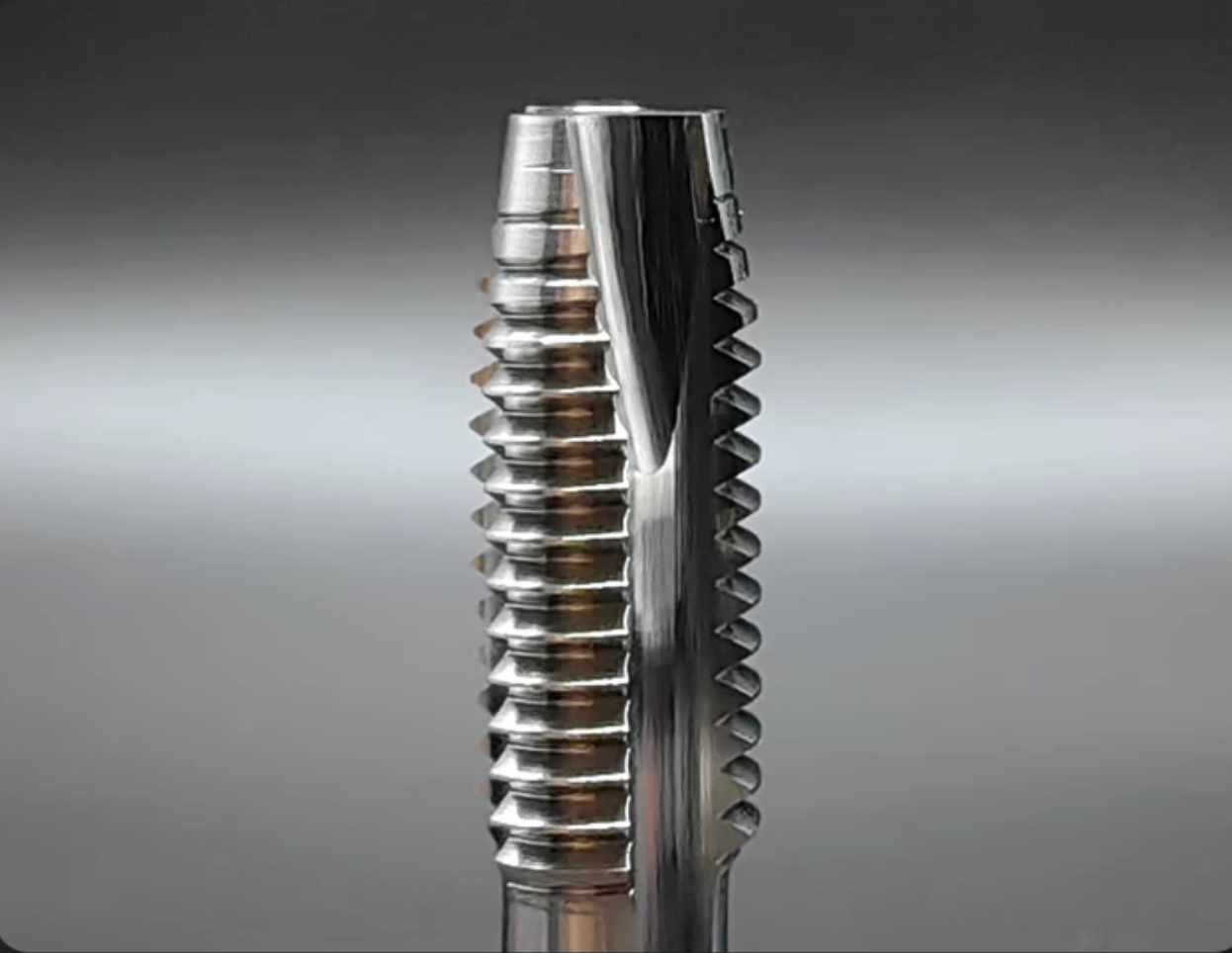
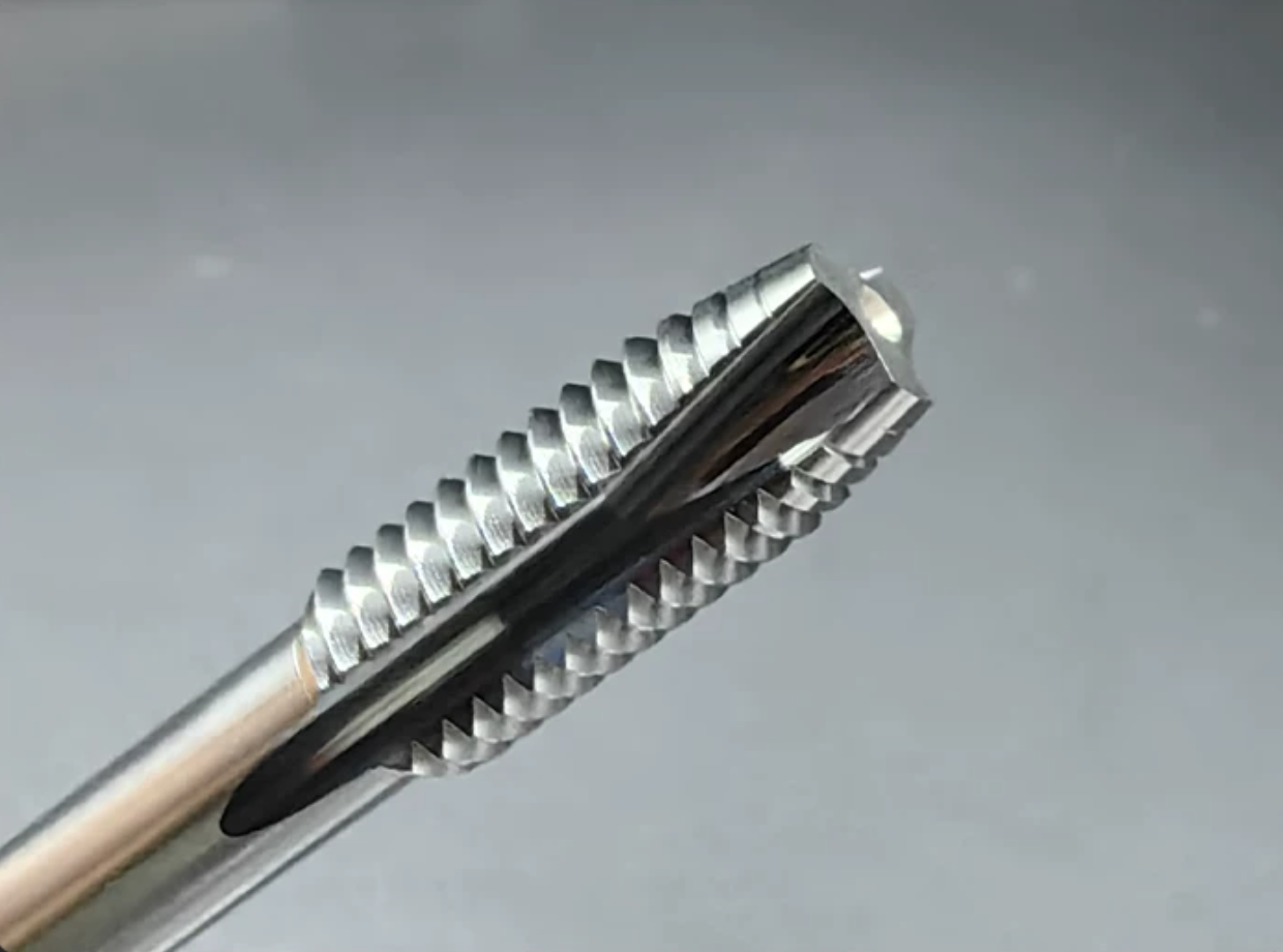
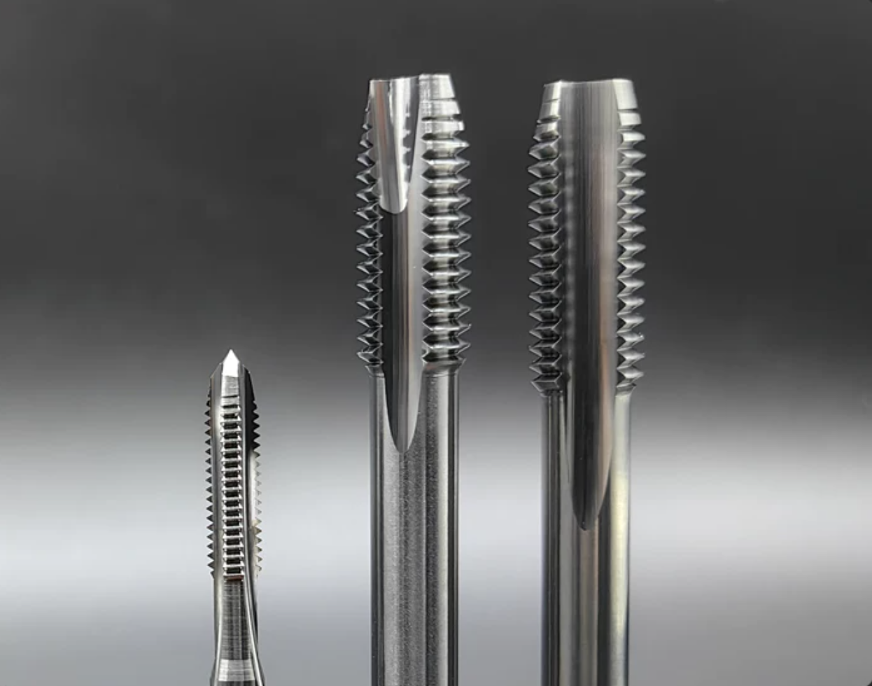
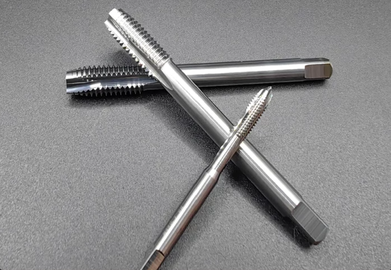
These solid carbide spiral point machine taps are designed for CNC production of internal metric threads in through holes. The straight-flute body and spiral point direct chips forward, away from the cutting zone, helping reduce chip recutting and support stable continuous tapping. Standard coarse- and fine-pitch models cover M2×0.4 to M20×2.5, with thread lengths from 10 to 30 mm and overall lengths from 48 to 100 mm. The rigid carbide construction supports dimensional consistency and wear resistance in stable machine setups. Thread tolerance, carbide grade, coating, chamfer geometry and coolant configuration can be customized for the workpiece and process.
Key Configuration
Forward Chip Evacuation
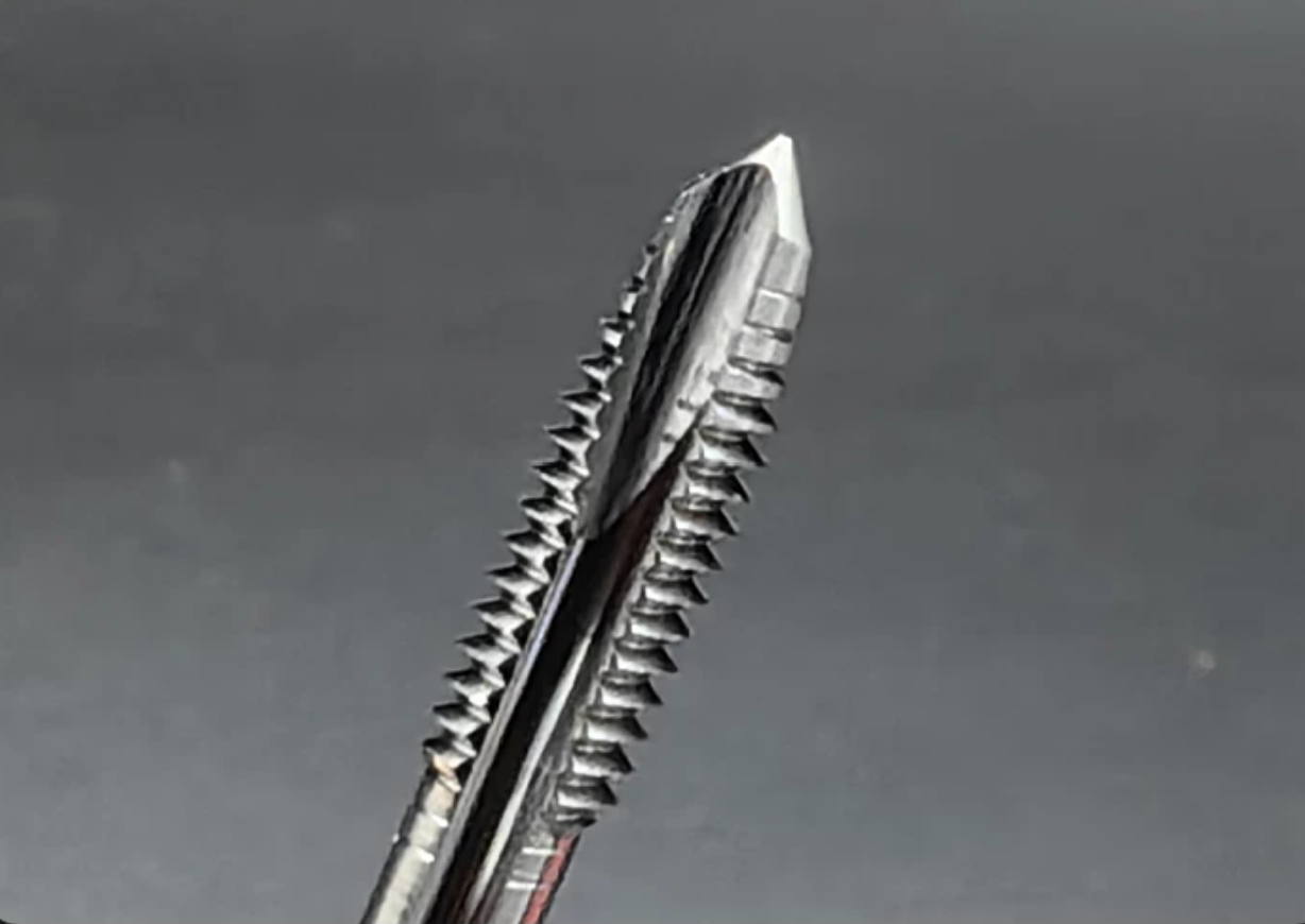
The spiral point drives chips ahead of the tap and out through the open bottom of the hole, reducing chip accumulation in the flutes.
Straight-Flute Rigidity
Straight flutes retain a strong core and work with the spiral point to support stable machine tapping in through-hole applications.
Coarse & Fine Metric Sizes
The catalog provides 13 coarse-pitch and 12 fine-pitch models, allowing selection by exact nominal diameter and pitch.
Solid Carbide Construction
The rigid substrate supports wear resistance and thread consistency when run in a precise holder on a stable machine setup.
Machining Advantages
Reliable Chip Direction
Forward chip flow helps keep chips away from the newly formed thread and minimizes flute packing.
Stable Thread Quality
Rigid carbide and controlled machine tapping support repeatable pitch diameter and flank finish.
Production Efficiency
The geometry is intended for continuous through-hole tapping cycles without periodic chip-breaking reversal.
Custom Application Matching
Carbide grade, coating, chamfer, tolerance and coolant design can be matched to the material and machine.
Recommended Application
Use this series for machine tapping of open through holes where chips can exit ahead of the tool. Material suitability depends on carbide grade, coating, thread size, hole depth, cutting speed, lubrication, holder and machine rigidity. Confirm the application before using the tap in interrupted holes, cross holes, unstable parts or difficult long-chipping materials.
Product Geometry
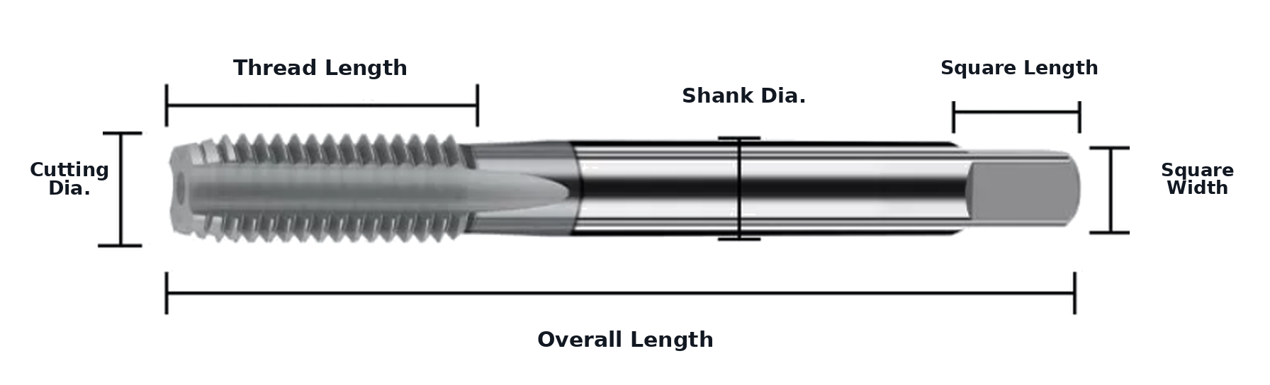
The dimensional drawing identifies cutting diameter, thread length, shank diameter, square width, square length and overall length.
Specifications & Standard Sizes
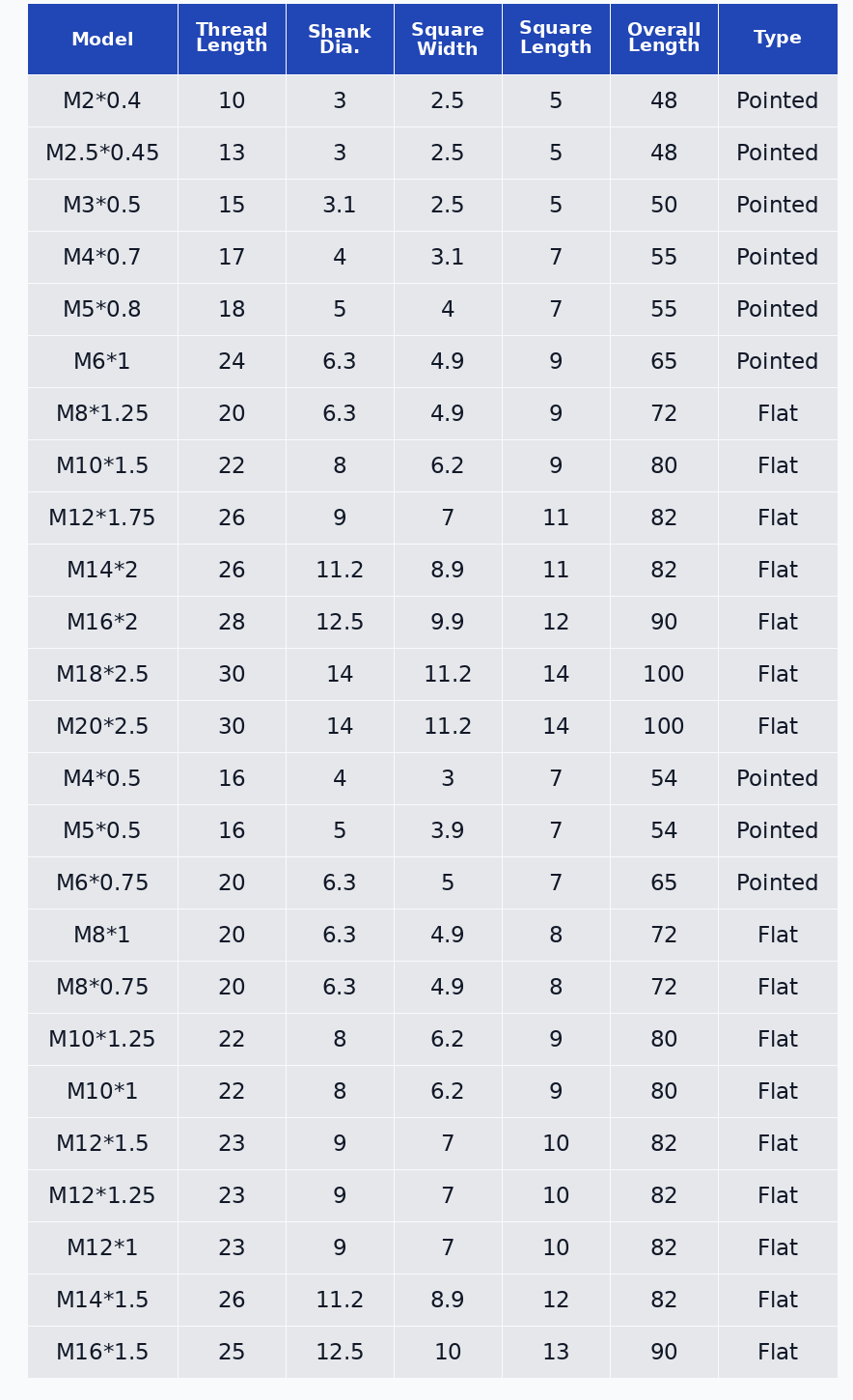
All dimensional values are in millimetres. Select the tap by nominal metric thread and exact pitch. Thread Length is the catalog threaded-section length; Shank Dia. is the cylindrical shank diameter; Square Width and Square Length define the drive square; Overall Length is the total tool length. Type reproduces the catalog designation “Pointed” or “Flat” without assigning an unconfirmed chamfer form.
Technical Configuration
| PARAMETER | STANDARD RANGE | SELECTION NOTE |
|---|---|---|
| Tap Construction | Solid carbide, straight flute with spiral point | For rigid machine tapping setups |
| Hole Application | Through holes | Provide sufficient breakthrough space for the chamfer and forward-ejected chips |
| Metric Thread Range | M2–M20 | Select the exact diameter and pitch combination listed |
| Pitch Range | 0.4–2.5 mm | Coarse and fine pitches are separate models |
| Thread Length | 10–30 mm | Confirm required full thread and breakthrough allowance |
| Диаметр хвостовика | Ø3–Ø14 mm | Match the tapping chuck or collet |
| Square Width | 2.5–11.2 mm | Verify compatibility with the holder drive |
| Square Length | 5–14 mm | Check axial engagement in the tap holder |
| Общая длина | 48–100 mm | Confirm machine travel, holder projection and work clearance |
| Catalog End Type | Pointed / Flat | Retained as catalog terminology; confirm detailed end geometry when required |
Metric Coarse-Pitch Size Matrix
Standard coarse-pitch models from M2×0.4 to M20×2.5.
| MODEL | THREAD LENGTH | SHANK DIA. | SQUARE WIDTH | SQUARE LENGTH | OVERALL LENGTH | TYPE |
|---|---|---|---|---|---|---|
| M2×0.4 | 10 | 3 | 2.5 | 5 | 48 | Pointed |
| M2.5×0.45 | 13 | 3 | 2.5 | 5 | 48 | Pointed |
| M3×0.5 | 15 | 3.1 | 2.5 | 5 | 50 | Pointed |
| M4×0.7 | 17 | 4 | 3.1 | 7 | 55 | Pointed |
| M5×0.8 | 18 | 5 | 4 | 7 | 55 | Pointed |
| M6×1 | 24 | 6.3 | 4.9 | 9 | 65 | Pointed |
| M8×1.25 | 20 | 6.3 | 4.9 | 9 | 72 | Flat |
| M10×1.5 | 22 | 8 | 6.2 | 9 | 80 | Flat |
| M12×1.75 | 26 | 9 | 7 | 11 | 82 | Flat |
| M14×2 | 26 | 11.2 | 8.9 | 11 | 82 | Flat |
| M16×2 | 28 | 12.5 | 9.9 | 12 | 90 | Flat |
| M18×2.5 | 30 | 14 | 11.2 | 14 | 100 | Flat |
| M20×2.5 | 30 | 14 | 11.2 | 14 | 100 | Flat |
Metric Fine-Pitch Size Matrix
Standard fine-pitch models from M4×0.5 to M16×1.5.
| MODEL | THREAD LENGTH | SHANK DIA. | SQUARE WIDTH | SQUARE LENGTH | OVERALL LENGTH | TYPE |
|---|---|---|---|---|---|---|
| M4×0.5 | 16 | 4 | 3 | 7 | 54 | Pointed |
| M5×0.5 | 16 | 5 | 3.9 | 7 | 54 | Pointed |
| M6×0.75 | 20 | 6.3 | 5 | 7 | 65 | Pointed |
| M8×1 | 20 | 6.3 | 4.9 | 8 | 72 | Flat |
| M8×0.75 | 20 | 6.3 | 4.9 | 8 | 72 | Flat |
| M10×1.25 | 22 | 8 | 6.2 | 9 | 80 | Flat |
| M10×1 | 22 | 8 | 6.2 | 9 | 80 | Flat |
| M12×1.5 | 23 | 9 | 7 | 10 | 82 | Flat |
| M12×1.25 | 23 | 9 | 7 | 10 | 82 | Flat |
| M12×1 | 23 | 9 | 7 | 10 | 82 | Flat |
| M14×1.5 | 26 | 11.2 | 8.9 | 12 | 82 | Flat |
| M16×1.5 | 25 | 12.5 | 10 | 13 | 90 | Flat |
How to Select
Starting Tapping Guidance
- Prepare the tap-drill diameter and entry chamfer according to the required thread percentage and workpiece drawing.
- Provide sufficient breakthrough clearance so the spiral point and forward-moving chips can exit freely.
- Use rigid or synchronized tapping with a precision holder and minimal radial runout.
- Set spindle speed and feed so axial feed equals spindle speed multiplied by the selected pitch.
- Use suitable tapping oil, emulsion or coolant for the material, coating and machine arrangement.
- Begin with conservative cutting data, monitor torque and inspect the first thread before batch production.
Dimension & Size Charts
Use the dimensional drawing to identify each tool feature and the size chart to confirm the exact catalog dimensions.
Технические ресурсы
Spiral Point Machine Tap Customization
Solid carbide spiral point machine taps can be configured for precision metric threading in through holes. Standard coarse- and fine-pitch models cover M2–M20 and pitches from 0.4 to 2.5 mm. Custom thread tolerance, chamfer geometry, thread length, straight-flute and spiral-point geometry, shank and drive-square dimensions, overall length, carbide grade, edge preparation, coating, coolant configuration and packaging can be reviewed according to the workpiece material, required thread depth, breakthrough clearance, machine synchronization and production conditions.
| PARAMETER | MANUFACTURING CAPABILITIES |
|---|---|
| Thread Standard | Metric coarse and fine threads; standard models cover M2–M20 with pitches from 0.4 to 2.5 mm |
| Hole Application | Through-hole tapping with sufficient breakthrough clearance for the chamfer and forward-ejected chips |
| Flute & Point Geometry | Straight-flute geometry with a spiral point; rake, chip space and point geometry can be optimized for the workpiece and cutting conditions |
| Thread Tolerance | Standard or drawing-defined internal-thread tolerance can be reviewed; the supplied size chart does not state a fixed tolerance class |
| Chamfer Geometry | Chamfer form and length can be selected for through-hole entry, cutting load and required thread completion; confirm where a specific form is required |
| Thread Length | Standard 10–30 mm; customized threaded-section length is reviewed against thread depth and breakthrough clearance |
| Диаметр хвостовика | Standard Ø3–Ø14 mm; custom shank dimensions can be reviewed for the selected tapping chuck or collet |
| Drive Square | Standard square widths 2.5–11.2 mm and square lengths 5–14 mm; custom dimensions can be matched to the holder drive |
| Общая длина | Standard 48–100 mm; special length is reviewed according to machine travel, holder projection and workpiece clearance |
| Catalog End Type | Pointed and Flat types are listed in the standard matrix; detailed end geometry can be confirmed where required |
| Carbide & Coating | Fine-grain solid carbide, edge preparation and application-specific coatings can be selected for material, hardness, lubrication and tool-life requirements |
| Coolant Configuration | External or optional internal-coolant design can be reviewed according to tap size, workpiece material, machine capability and production volume |
Услуги по производству под брендом OEM и под частной торговой маркой
OEM manufacturing and private-label supply are available for cutting-tool distributors, tooling brands and repeat-production customers. Metric thread size, pitch, product code, coating reference, customer logo, labels and protective packaging can be configured according to the approved spiral point tap specification.
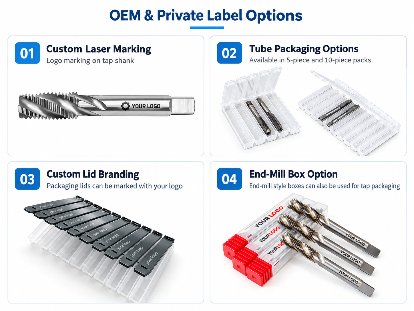
Laser Marking
Customer logos, metric size and pitch, product code, coating reference and batch identification can be marked according to the available shank area.
Custom Labels & Packaging
Individual protective tubes, size-coded labels and private-label packaging can be prepared for distributor and tooling-brand programs.
Commercial Terms
In-stock standard taps can normally be dispatched in 1–2 working days. Minimum order is 10 pieces per size; custom samples and repeat supply are confirmed by specification.
Technical Workflow
A structured review confirms the metric thread, through-hole conditions, spiral point geometry, dimensions, carbide grade, coating and identification before standard, customized or private-label taps enter production.
Inquiry
Submit metric size, pitch, tolerance, material, hole depth, breakthrough, machine, holder and quantity.
Engineering
Review spiral point, straight flutes, chamfer, thread length, shank, square, carbide, coating and coolant.
Commercial
Confirm quotation, MOQ, sample conditions, schedule, marking, packaging and delivery terms.
Production
Carbide preparation, CNC thread and flute grinding, spiral-point processing, edge preparation, coating and marking.
Quality Control
Inspect thread form, pitch, dimensions, spiral point, runout, edges, coating and identification.
Quality, Inspection & Delivery
Our solid carbide spiral point machine taps are controlled through carbide material verification, precision CNC grinding, in-process measurement and final inspection. Critical features including metric thread form, pitch, spiral-point geometry, straight flutes, thread length, shank diameter, drive-square dimensions, overall length, radial runout, cutting-edge condition, coating appearance and product identification are checked against the selected standard model or approved custom drawing before packing.

Three-Stage Quality Control
Inspection checkpoints are arranged throughout production to support metric thread accuracy, forward-chip geometry, dimensional consistency and repeat-order stability.
Incoming Material Control
Carbide substrate grade, blank diameter, blank length and supplied material information are checked against the confirmed tap specification.
Thread & Spiral-Point Control
Thread profile, pitch, straight flutes, spiral point, chamfer, thread length, shank and drive-square dimensions are monitored during CNC grinding.
Final Tap Inspection
Finished taps are reviewed for model, pitch, dimensions, runout, cutting edges, coating, laser marking and packing identification.
Key Inspection Characteristics
Inspection requirements are confirmed according to the selected standard model and the approved metric thread or custom tap drawing.
| INSPECTION ITEM | CONTROL FOCUS | CONFIRMATION BASIS |
|---|---|---|
| Metric Thread & Pitch | Nominal size, pitch spacing, profile and tooth consistency | Selected model, approved thread specification or drawing |
| Spiral Point | Point orientation, cutting geometry and forward-chip path | Approved manufacturing configuration |
| Straight Flutes & Chamfer | Flute consistency, rake, clearance and chamfer geometry | Standard tool specification or custom drawing |
| Thread Length | Threaded-section length and transition geometry | Catalog size matrix or approved drawing |
| Диаметр хвостовика | Clamping-section diameter, straightness and surface condition | Catalog dimensions or approved custom specification |
| Drive Square | Square width, square length and holder engagement | Selected model and holder interface |
| Overall Length & End Type | Total length and Pointed or Flat catalog end style | Standard matrix or approved drawing |
| Runout & Edge Condition | Concentricity, chipping, burrs and cutting-edge consistency | Internal inspection criteria and approved order requirement |
| Coating & Identification | Surface appearance, coverage, size, pitch, product code and batch marking | Approved coating, marking and packaging specification |
Measurement & Batch Traceability
Optical measurement, thread inspection tools and dimensional gauges are selected according to the feature and tolerance being checked.
Thread Inspection
Metric thread form, pitch and drawing-defined tolerance are checked against the approved specification.
Optical Measurement
Spiral point, chamfer, flutes, cutting geometry and dimensional features are measured with suitable equipment.
Edge Inspection
Cutting-edge preparation, edge condition and visible defects are checked before shipment.
Batch Identification
Order, size, pitch, product code and batch information are linked where required for repeat supply.
Protective Packaging Process
Finished carbide taps are individually protected to reduce contact damage to the chamfer and cutting edges and to maintain clear size and batch identification.


Bulk-Order & Export Packaging
Bulk orders can be arranged with sizes and pitches separately labelled, together with reinforced cartons, protective wrapping, palletized loading or export cases according to quantity and transportation requirements.

Delivery Coordination
In-stock standard taps can normally be dispatched within 1–2 working days. Minimum order is 10 pieces per size. Custom-tool lead time is confirmed after thread specification, geometry, dimensions, material application, coating, quantity, inspection, marking and packaging requirements are approved.
FAQ & Technical Support
Review common selection, application and ordering questions for solid carbide spiral point machine taps used in metric through-hole threading. Topics include forward chip evacuation, coarse- and fine-pitch selection, tap-drill preparation, machine requirements, customization and OEM supply.
Product & Application FAQs
Selection and application guidance for precision CNC tapping of metric through holes.
What is a solid carbide spiral point machine tap used for?
It is designed for machine tapping of internal metric threads in through holes. The straight-flute body provides rigidity, while the spiral point directs chips forward through the open bottom of the hole. It is intended for precise CNC or synchronized tapping in a stable setup.
How does the spiral point control chips?
The angled cutting feature at the tap point breaks the chip and pushes it ahead of the tool. This helps keep chips away from the finished thread and reduces flute packing, provided the through hole has enough breakthrough space for chips to exit.
Can this tap be used in blind holes?
It is not the preferred geometry for a conventional blind hole because the spiral point pushes chips toward the hole bottom. For blind holes, select a spiral-flute or another tap designed to evacuate chips back toward the entry unless the process has been specifically engineered and validated.
What standard metric sizes are available?
The standard range contains 25 models: 13 coarse-pitch sizes from M2×0.4 to M20×2.5 and 12 fine-pitch sizes from M4×0.5 to M16×1.5. Thread lengths are 10–30 mm, shanks Ø3–Ø14 mm and overall lengths 48–100 mm.
How do I choose the correct tap-drill diameter?
Choose the tap-drill diameter from the required metric size, pitch, thread engagement, tolerance and workpiece material. An undersized hole increases torque and breakage risk; an oversized hole reduces thread engagement. Follow the component drawing or an approved tap-drill chart and verify the first part.
Why choose solid carbide instead of HSS?
Solid carbide provides higher rigidity and wear resistance, supporting stable thread size and production consistency on rigid machines. HSS is tougher and may be preferable on less stable equipment, manual operations or interrupted conditions. Carbide requires accurate alignment, low runout and controlled tapping synchronization.
Which workpiece materials can be tapped?
Material suitability depends on carbide grade, coating, chamfer, rake geometry, thread size, hole depth and lubrication. Provide the exact material grade and hardness so the tool configuration and starting data can be reviewed. The supplied dimensional chart does not assign one universal material range.
Ordering & Customization FAQs
Information for distributors, tooling brands and industrial customers sourcing standard or custom spiral point carbide taps.
Can custom spiral point carbide taps be manufactured?
Yes. Custom metric size, pitch, tolerance, chamfer, thread length, spiral-point and flute geometry, shank, drive square, overall length, carbide grade, coating and coolant configuration can be reviewed from the tap or component drawing.
What information is required for an accurate quotation?
Please provide metric thread size and pitch, tolerance, workpiece material and hardness, through-hole depth, breakthrough clearance, tap-drill diameter, machine and holder, coolant method, coating preference, thread quantity per part, order quantity, marking and packaging requirements.
Are OEM marking and private-label packaging available?
Yes. Laser marking can include the customer logo, metric size and pitch, product code, coating reference and batch number. Protective tubes, custom labels and private-label packaging can also be prepared for distributor and OEM programs.
What are the MOQ and lead time?
The minimum order is 10 pieces per size. In-stock standard taps can normally be dispatched within 1–2 working days. Custom-tool lead time is confirmed after thread specification, geometry, dimensions, material, coating, inspection, marking and packaging requirements are approved.
Technical Downloads
Access dimensional and size references for selecting solid carbide spiral point machine taps for metric through holes.
Spiral Point Tap Size Chart
Metric coarse and fine models, thread lengths, shanks, drive squares and overall lengths.
Spiral Point Tap Dimensions
Reference drawing for cutting diameter, thread length, shank, drive square and overall length.
The charts are product-selection references. Final tap specification and cutting data should be confirmed according to thread tolerance, material, hole depth, breakthrough clearance, tap-drill diameter, coating, coolant, holder and machine conditions.
Need Sizes, Pricing or Custom Options?
Send us the required tool type, sizes, quantities, workpiece material and any OEM or custom requirements. We will confirm suitable specifications, availability, lead time and quotation details.
Drawings, size lists and reference photos are welcome.