
How to Reduce Chatter in End Milling: Tool, Holder, and Cutting Strategy
To reduce chatter in end milling, start with tool projection, mounting and workpiece support, then check engagement and cutting data. Use where the problem occurs to choose an adjustment and inspect the result on the part.
If a customer reports vibration, ask for the current tool model, an installed-tool photo and the machining conditions. Those details help you discuss the cause and decide whether a different end mill is worth evaluating.
For the wider selection process, see our solid carbide end mill selection guide.
Quick Answer
Check the setup
Review stick-out, mounting, runout, edge condition and workpiece support.
Review the cut
Check engagement and corner loads. Recalculate feed per tooth when RPM changes.
Match and verify
Select suitable geometry and reach; compare finish, dimensions and edge wear.
Table of Contents
Signs of End Mill Chatter
Chatter is unstable cutting vibration that can leave repeated marks and damage the cutting edges. A noisy cut or poor finish is a reason to investigate, not enough evidence to identify the cause.
Look at the wall, each cutting edge and the point in the toolpath where the problem begins. Compare those observations with the setup and cutting data. Chip recutting, built-up edge, runout and tool wear can also affect finish and sound.
Where Does Chatter Occur?
Where vibration starts helps narrow the search. Use the examples below to choose your first checks.
| Customer feedback | Ask or inspect | First check |
|---|---|---|
| “Only the inside corners chatter.” | Does the straight section cut normally? Does engagement increase in the corner? | Review the corner path and local feed/engagement before changing cutters. |
| “It starts when we extend the tool.” | Actual stick-out, cutting length, required clearance and holder position. | Remove unnecessary projection or review the reach arrangement. |
| “One flute chips much more than the others.” | Photos of every flute, holder condition and measured runout. | Check uneven loading, mounting and edge damage. |
| “The finishing wall has repeated marks.” | Remaining stock, tool wear, workpiece support and cutting data. | Check for variable engagement and loss of support during finishing. |
| “It gets worse as the pocket gets deeper.” | Chip buildup, available reach and contact with the neck or holder. | Review chip removal and clearance at the actual depth. |
| “Both the old and new cutters do it.” | Complete specifications and whether either ran successfully in this setup. | Review the shared setup and conditions as well as both tool designs. |
Swipe horizontally to compare all columns on mobile.
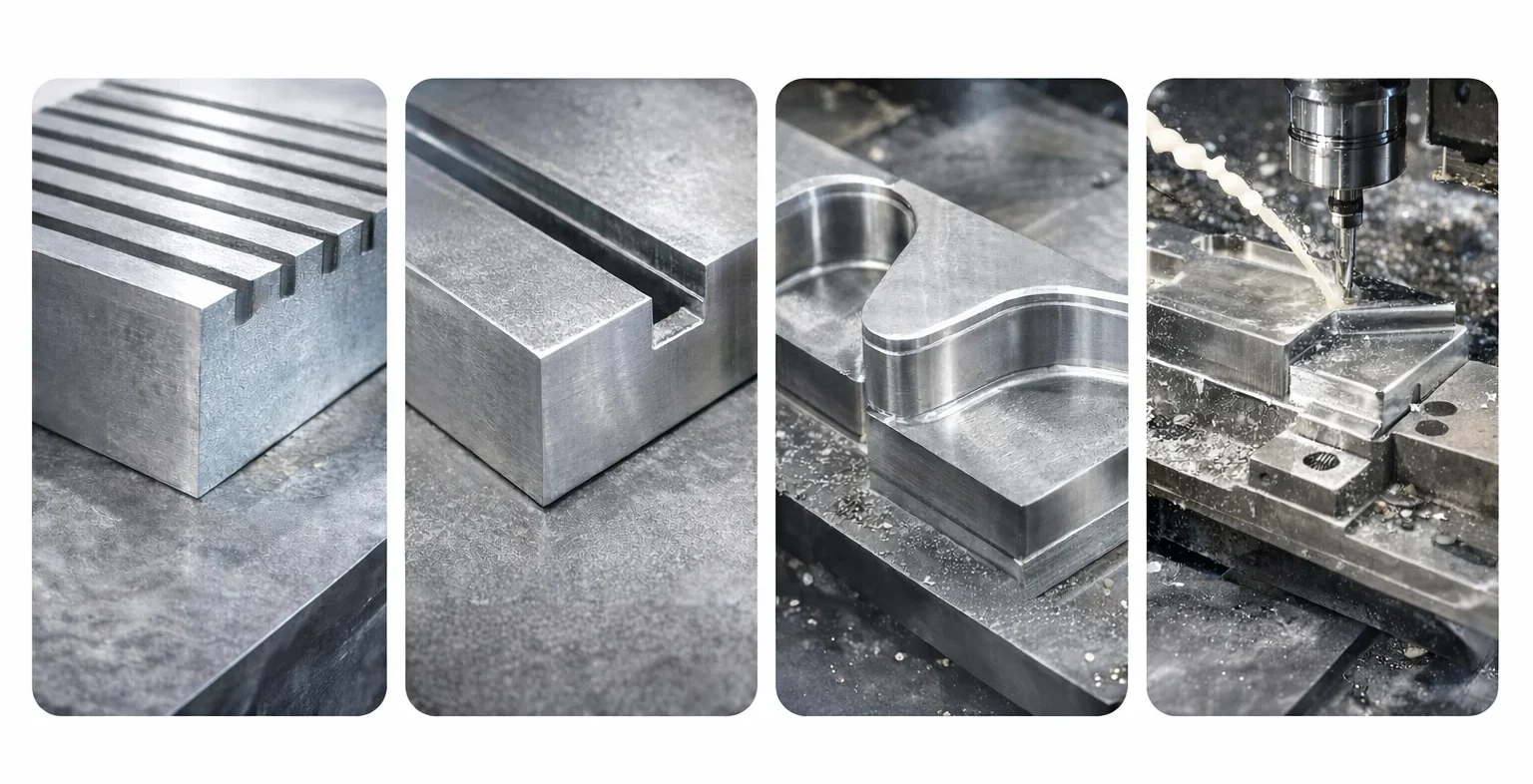
7 Checks to Reduce Chatter in End Milling
Select the checks that match the symptom. Record the starting conditions and make one planned adjustment at a time; an RPM change and its corresponding feed recalculation form one planned adjustment.
| Check | What to check or change | What to compare |
|---|---|---|
| 1. Installed tool length | Check access and clearance. Reduce unnecessary stick-out while meeting the holder’s clamping requirements. | Wall marks and dimensions at the same feature after shortening the projection. |
| 2. Holder and mounting | Check shank fit and contact surfaces. Clean and remount correctly; measure assembly runout. | Runout before and after remounting, plus uneven wear between flutes. |
| 3. Cutting-edge condition | Inspect every flute for wear, chipping and attached material. Use an undamaged cutter for further evaluation. | When damage first appears and which edges are affected under the recorded conditions. |
| 4. Workpiece support | Check thin or unsupported sections. Improve support against the cutting forces where practical. | Whether marks are confined to unsupported areas or increase as the wall becomes thinner. |
| 5. Cutting engagement | Review axial depth, radial width and corner loads. Consider lower engagement or a smoother path for the operation. | Results in straight sections versus corners, and the effect on finish and cycle time. |
| 6. Speed and feed | Try a controlled RPM adjustment within recommended limits. Recalculate feed per tooth using the intended engagement. | Surface marks, dimensions and edge condition for each recorded RPM/feed combination. |
| 7. Chips and material suitability | Clear chip accumulation and check coolant/air delivery. Verify the model and cutting data for the material. | Whether the problem grows with pocket depth or chip buildup, and whether edge damage continues. |
Swipe horizontally to compare all columns on mobile.
For heavy stock removal in steel, compare the HRC45 roughing end mill and HRC55 roughing end mill against the material grade and hardness. Serrated edges break chips into smaller segments; engagement and chip evacuation still need attention. Leave stock for a separate finishing pass where required.
Cutting Length, Reach and Stick-Out Are Different
Cutting length is the fluted section. Reach describes access to a recessed feature, including any neck clearance; confirm how the supplier measures it. Stick-out is the installed tool projection beyond the holder. Overall length alone does not tell you any of these three requirements.
For a deep feature, a relieved neck may provide access without unnecessary flute length. Match the neck clearance, cutting length and installed projection to the drawing.
When the feature requires reach rather than a longer cutting edge, compare the long-neck series against the part drawing. The relieved neck must clear the wall throughout the toolpath.
When RPM Changes, Check Feed per Tooth
For ordinary milling feed calculations: feed per tooth = feed rate ÷ (RPM × flute count). With feed in mm/min, the result is mm/tooth. Keeping the same feed rate while changing RPM changes the load per tooth.
Use the selected model’s starting data and account for engagement, especially at low radial widths and inside corners. Reducing every setting together can make the result difficult to interpret. See the end mill speeds and feeds guide for calculation details.
When to Change the End Mill
Consider a replacement when the current tool has excessive cutting length, unsuitable geometry, inadequate chip space or damaged edges. Compare those details as well as diameter.
| What you find | Tool option to review | Confirm before ordering |
|---|---|---|
| More flute length than the feature needs | A shorter cutting-length configuration. | Required cutting depth, holder clearance and actual installed projection. |
| Deep access with unnecessary long flutes | A suitable neck-relieved or reach configuration. | Neck diameter, reach measurement, clearance and cutting length. |
| Persistent chatter after relevant setup checks | Variable-pitch or variable-helix geometry for the application. | The actual model specification, material recommendation and trial conditions. |
| Chip packing during slots or pockets | Geometry and flute space suited to that operation. | Entry capability, chip-removal path and engagement. |
| Wrong material range or damaged edges | A suitable material-specific model or an undamaged replacement. | Exact grade, condition, end profile, edge preparation and coating. |
Swipe horizontally to compare all columns on mobile.
Variable pitch changes the spacing between flutes. Variable helix varies the helix angle between flutes. These are different design features; a cutter may use one or both. Ask for the model specification instead of relying on the label “anti-vibration.”
Use the material, operation and setup to compare tool designs. If variable pitch or variable helix is required, include it in the model specification.
Tool Options for Reach and Finishing
For recessed features, compare the required clearance and cutting length before choosing a reach configuration.
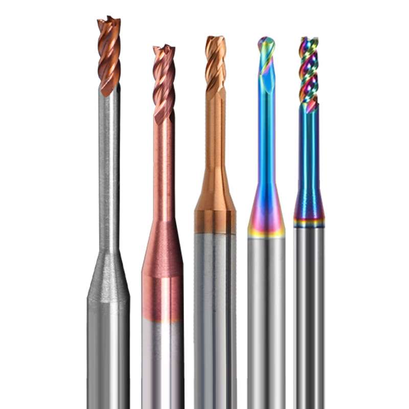
Long-neck end mill series
For recessed features needing neck clearance. Match the end profile, cutting length and reach.

Long-neck micro square
For fine ribs, narrow slots and small cavities. Check neck diameter and mounted runout.
For general side milling or finishing, compare the HRC55 steel square-end range or the separate stainless-steel end mill range according to the material and operation.
For other configurations, browse the complete end mill range and the HY Cutting Tools end mill series guide.
What to Ask Your Customer
Start with what the customer already has. A tool code, installation photo and a description of where the problem starts are more useful than an incomplete list of guessed parameters. Ask for the remaining details as the review develops.
| Information | What to send |
|---|---|
| Current tool | Model code or catalog page; cutting diameter, shank, cutting length, overall length and end shape. |
| Material and job | Exact grade and condition, hardness if known, operation and required feature depth. |
| Installed setup | Tool stick-out, holder type, clamping arrangement and measured runout if available. |
| Cutting data | RPM, feed rate with units, axial cutting depth and radial cutting width. |
| Problem evidence | Where it happens, wall and edge photos, coolant/chip conditions and a machining video if available. |
| Earlier results | Which tool worked before, what changed, and whether the same symptom occurs with another cutter. |
Swipe horizontally to compare all columns on mobile.
“Feed 500” or “depth 10” needs clarification: include units and distinguish axial depth from radial width. A video helps explain the complaint, but it cannot establish runout, exact dimensions or the cause on its own.
Information to forward to your customer
Current tool/model: ___ Material grade: ___
Operation and required depth: ___
Tool stick-out and holder: ___
RPM: ___ Feed + units: ___
Axial depth: ___ Radial width: ___
Where the problem starts: ___
Attach tool, edge and setup photos; add a machining video if available.
How to Verify the Result
Record the starting finish, dimensions and edge condition. Keep the material, feature, holder, projection and inspection method comparable except for the planned change. If replacing the cutter, also record differences in dimensions, geometry and recommended cutting data.
| Result to check | What to record | How to assess it |
|---|---|---|
| Surface quality | Photos of the same area; roughness measurements if specified. | Have repeated marks decreased, and does the surface meet the drawing requirement? |
| Dimensional control | The same feature measured by the same method. | Has consistency improved, and do dimensions remain within the required tolerance? |
| Cutting-edge condition | Photos of all flutes after comparable cutting time or work. | Has early chipping decreased? Check whether wear is more even. |
| Process performance | RPM, feed, engagement, cycle time and observations across repeated parts. | Is the improvement repeatable, and what productivity change accompanied it? |
Swipe horizontally to compare all columns on mobile.
A quieter cut is useful feedback; verify the part and edges too. Record both the quality improvement and any cycle-time change. Longer-term tool-life claims need comparable results over enough machining time.
If you are evaluating a new supplier or a replacement model, use the cutting tool trial-order guide to agree quantities, test records and acceptance requirements before expanding the order.
Common Questions About End Mill Chatter
My old cutter ran well. Why does the new one chatter?
Compare more than the diameter: cutting length, flute count, helix, edge geometry and installed projection may differ. Also inspect the holder and mounting. Record the old and new tool details alongside the cutting data to see what changed.
Can I use the same cutting parameters after changing the cutter?
Use the new model’s recommended starting data for the material and operation. A change in flute count or RPM changes feed per tooth at the same feed rate. Record the new settings so you can compare the results.
Should I always slow the spindle down when chatter starts?
Not always. Try a controlled RPM adjustment within the tool’s recommended range and recalculate feed for the intended feed per tooth. Reducing feed too far can lead to rubbing. Compare wall marks and edge condition after the adjustment.
The cavity is deep. Do I need longer flutes?
Only when the cut needs that much cutting-edge contact. A shorter cutting section with a relieved neck may provide access to a deep feature. Review the neck diameter, reach and holder clearance against the drawing.
Do more flutes or a higher HRC series mean less chatter?
Those labels do not tell you whether a cutter has variable pitch or variable helix. Choose the material range and flute space for the operation, then look at the exact geometry if chatter control is a requirement.
How do I know whether the trial has actually improved the cut?
Compare the same feature for surface marks, dimensions and edge wear after comparable cutting time or work. Record cycle time as well. A quieter cut is useful, but the part still needs to meet its drawing requirements.
For general ordering and after-sales questions, see our buyer FAQs.
Related End Mill Guides


Need Help Comparing a Replacement?
Send the current tool model or photos, material and where vibration starts. Include the cutting data and an installed-tool photo if available.
Technical references
For additional background, see Sandvik Coromant’s milling troubleshooting guide, Harvey Performance’s explanation of variable tool geometry and Harvey Performance’s speeds and feeds introduction. These explain general principles; use cutting data for your selected tool and application.