How to Choose a Solid Carbide Drill: Complete Selection Guide
Choosing a solid carbide drill starts with the hole—not the coating color or tool price.
Diameter, depth, tolerance, workpiece material, chip behavior, coolant delivery and machine stability all affect the choice. Solid carbide provides high rigidity and wear resistance on suitable CNC equipment, but it is less forgiving of runout, vibration and poor clamping than tougher HSS.
Treat the drill, holder, coolant system, machine and workpiece as one cutting system. This guide narrows the options without assuming that one geometry, coating or speed range works everywhere.
Quick Solid Carbide Drill Selection Table
Use this table as a starting point, then confirm the exact drill series and cutting data with the tool supplier.
| Aplicativo | Practical Starting Choice | Main Point to Confirm |
|---|---|---|
| General steel, shallow hole | Short, steel-specific coated drill | Tolerance, chip shape and coolant |
| Steel or stainless steel, medium-depth hole | Material-specific drill; through coolant when evacuation is difficult | Material grade, L/D and coolant supply |
| Stainless, titanium or heat-resistant alloy | Dedicated ISO M/S geometry with reliable internal coolant | Heat, edge strength and chip control |
| Alumínio e ligas não ferrosas | Sharp, polished geometry; uncoated or validated low-friction coating | Built-up edge, chip space and silicon content |
| Ferro fundido | ISO K geometry and wear-resistant grade selected for the actual cast iron | Abrasiveness, interrupted cuts and wet/dry recommendation |
| Hardened steel | Drill specifically rated for the actual workpiece hardness | Machine rigidity, runout and toolmaker cutting data |
| Beyond the standard 3D/5D/8D range | Dedicated deep-hole drill and specified pilot procedure | Pilot, coolant and entry/withdrawal cycle |
| Close-tolerance finished hole | Validated high-precision drill, or drill followed by reaming/boring | Required ISO tolerance, roundness and surface finish |
Swipe horizontally to view the complete table.
1. Define the Finished Hole Before Choosing the Drill
Sandvik Coromant identifies diameter, depth and hole quality as the three basic starting points. Add the hole form and entry/exit conditions before selecting a tool.
Diameter, Depth and L/D Ratio
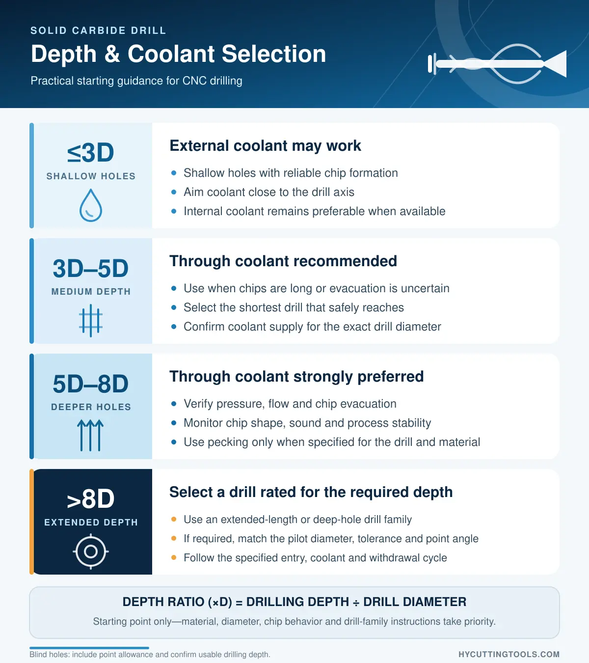
The length-to-diameter ratio comes from drilling depth and diameter. A 5D designation normally means a maximum drilling depth of approximately five times diameter; it does not describe overall tool length.
Choose the shortest drill that safely reaches the depth. Shorter tools and overhangs are more rigid and normally improve accuracy and tool life.
Through Holes, Blind Holes and Point Allowance
For a blind hole, distinguish full-diameter cylindrical depth from total depth including the point. Check point length and maximum usable depth on the drawing. For a through hole, allow for breakthrough and identify a flat, angled or interrupted exit.
Tolerance and Surface Finish
Drill diameter tolerance, shank tolerance and achievable hole tolerance describe different features. One Sandvik general-purpose solid carbide series, for example, lists H8–H9 holes; dedicated high-precision drills may work closer under controlled conditions.
If the drawing requires H7, tight roundness or a demanding finish, confirm that the drill and setup are validated for it. Otherwise, plan solid carbide reaming or fine boring. Reaming is a high-precision finishing process, not another drilling pass.
Special Hole Forms
A flat bottom, counterbore, chamfer or several diameters may require a purpose-designed tool. A custom carbide step drill can combine features, but chip evacuation and edge strength still limit the design.
2. Choose a Solid Carbide Drill by Workpiece Material
Confirm the alloy, hardness, heat treatment, chip behavior and abrasiveness—not only the ISO group.
| ISO Material Group | Typical Machining Issue | Drill Features to Evaluate |
|---|---|---|
| PAço | Changing chip behavior across carbon and alloy grades | Balanced edge strength, controlled chip formation and a suitable coated grade |
| MAço inoxidável | Work hardening, adhesive wear, heat and long chips | Material-specific point/flute design, polished chip paths and reliable coolant |
| KFerro fundido | Abrasive wear, casting skin and interrupted cuts; usually short chips | Wear-resistant grade and geometry matched to gray, ductile or compacted graphite iron |
| NAluminum and non-ferrous | Built-up edge, adhesion and high chip volume | Sharp edge, polished flutes, adequate chip space and uncoated or suitable low-friction surface treatment |
| STitanium and heat-resistant alloys | Low thermal conductivity and high cutting-zone temperature | Dedicated geometry, strong edge preparation, effective coolant and conservative starting data |
| HHardened steel | High wear and risk of edge chipping | Drill rated for the actual hardness, very stable clamping and low runout |
Swipe horizontally to view the complete table.
For stainless steel, coating alone is not the solution. Kennametal’s SGL drill, for example, combines AlTiN-coated fine-grain carbide with web thinning, gashing, a dedicated flute and polished surfaces. Geometry, substrate, finish and coating work as a system.
For aluminum, uncoated carbide can be the high-performance choice. Kennametal’s HPS drill uses uncoated fine-grain carbide, a sharp edge, enlarged flutes and polished chip surfaces to reduce built-up edge. DLC can suit some non-ferrous applications, but is not an automatic upgrade.
3. Check the Drilling Condition
A flat, stable entry loads the drill differently from an incline or cross hole. Angled entry/exit, curved surfaces and interruptions can load one edge before the other.
Use an approved geometry or prepare a flat/pilot feature. Entry, exit and cross-hole feed reductions are product-specific; do not apply one universal percentage.
For stacked plates, clamp layers securely and eliminate gaps. Dissimilar stacks may need dedicated geometry to control thrust, burrs and chips in more than one material.
A versatile drill simplifies small mixed batches; repeat production may justify an optimized or combination tool.
4. Select Drilling Depth and Coolant Delivery
Standard families commonly include 3D, 5D and 8D versions. Select the shortest one covering usable depth, breakthrough and point allowance.
External Coolant or Through Coolant?
External coolant can work in shallow holes with reliable chips. Aim it close to the drill axis and provide adequate flow. Internal coolant reaches the edges more directly and is generally more secure for long chips and deeper holes.
Sandvik’s drilling guidance favors internal coolant beyond 3×D or when chip jamming is a risk, and advises against dry drilling in ISO M/S applications. Required pressure and flow still depend on diameter, channel size, material and drill series.
Deep Holes and Pilot Drilling
For holes beyond a standard drill’s rated depth, select an extended-length or deep-hole drill family designed for the required depth, workpiece material and coolant conditions.
Some long drills require a pilot hole, while others use a different entry procedure. If a pilot is required, its diameter, tolerance, point angle and depth must match the long drill. Follow the drill manufacturer’s specified entry speed, coolant sequence, cutting cycle and withdrawal procedure.
Use peck drilling only when it is specified for the drill family and workpiece material. Many through-coolant carbide drills are designed for continuous penetration after correct entry, while particular materials or drill series may require a different cycle.
5. Compare Drill Geometry and Specifications
Point Geometry, Web Thinning and Gash
Point angle is only one part of the design. Lip shape, chisel edge, web thinning, relief and edge preparation affect centering, thrust, chip formation and strength. A self-centering drill may avoid spotting on a suitable flat surface, but not on every irregular entry.
Flutes and Margins
Flute cross-section and finish affect chip space, coolant flow and friction. Margins guide the drill; extra margins can improve guidance in some interruptions but also add contact. Evaluate the complete design.
Read the Dimensional Drawing
Confirm cutting diameter/tolerance, shank diameter/tolerance, flute length, point length, overall length and maximum depth. An h6 shank does not make the drill diameter or finished hole h6.
6. Select the Carbide Substrate and Coating
The substrate balances hardness, toughness and wear resistance. Coating can improve heat, abrasion or adhesion resistance, but cannot correct poor geometry, chip evacuation or runout.
For ferrous and heat-resistant materials, suitable families may use PVD TiAlN, AlTiN or TiSiN. Choice depends on the grade design, edge preparation, material and conditions. Aluminum may favor polished uncoated carbide or a validated low-friction coating such as DLC.
Do not use these shortcuts:
- Treating “HRC45,” “HRC55” or “HRC65” as coating names
- Assuming every tool sold for a given HRC range uses the same coating
- Identifying a coating only from gold, bronze, violet, blue or black appearance
- Selecting the coating before confirming material, depth, coolant and geometry
HRC labels normally describe an intended workpiece-hardness range or supplier series. Color varies with composition, thickness, process and post-treatment; confirm the specification.
7. Check the Machine, Holder and Runout
Solid carbide drilling needs a rigid spindle, secure workholding and accurate holder. Use minimal overhang and a clean precision collet, hydraulic chuck or shrink-fit holder compatible with the coolant method.
As a general guideline, Sandvik recommends runout within 20 μm. Small-diameter or close-tolerance work may require tighter control, so the drill supplier’s limit takes priority.
Confirm spindle speed, power, torque, coolant pressure and flow. If the machine cannot support the operating window, another drill system may be safer than unlimited data reductions.
8. Set Starting Speeds and Feeds
For metric drilling, spindle speed and penetration rate can be calculated as:
n = (1000 × Vc) ÷ (π × Dc)
vf = fn × n
These Sandvik drilling formulas calculate machine settings; they do not select Vc or fn.
Take starting values from the exact drill series and material subgroup, then review depth, coolant, holder, entry/exit and stability. Do not copy values from a drill with different geometry or grade.
9. Common Solid Carbide Drill Selection Mistakes
| Selection Mistake | Why It Causes Trouble |
|---|---|
| Selecting only by diameter | Ignores depth, tolerance, material and coolant |
| Choosing a longer drill “for flexibility” | Reduces rigidity and increases deflection risk |
| Using external coolant without checking chip evacuation | Can allow chip packing, heat and breakage |
| Choosing coating by color | Color does not reliably identify composition or application |
| Treating an HRC series name as the coating | Confuses workpiece application range with surface treatment |
| Ignoring runout and holder condition | Overloads one cutting edge and reduces hole quality and tool life |
| Promising H7 from any carbide drill | Achievable tolerance is tool- and setup-specific |
| Applying one speeds-and-feeds table to every drill | Ignores diameter, grade, geometry and material subgroup |
Swipe horizontally to view the complete table.
10. When a Solid Carbide Drill Is Not the Best Choice
Solid carbide is not always the lowest-cost option.
- HSS or cobalt drills: consider for less-rigid, lower-speed equipment where toughness and initial cost matter more than maximum productivity.
- Exchangeable-tip or modular drills: use replaceable heads to balance productivity and replacement cost in suitable diameters.
- Indexable U drills: often suit larger holes and productive rough holemaking. See our U drill selection guide.
- Reamers or fine boring tools: use when tolerance, roundness or finish exceeds the drill’s validated capability.
- Flat-bottom or step drills: use for flat bottoms, shoulders, chamfers or multiple diameters.
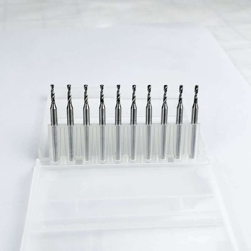
You can review standard and customized options in our solid carbide drill range, including 5D through-coolant drills.
11. Final Solid Carbide Drill Selection Checklist
For a recommendation or quotation, prepare:
- Workpiece material, grade and hardness
- Hole diameter and required tolerance
- Full-diameter depth and total depth
- Through hole or blind hole
- Entry, exit and any cross-hole condition
- Required surface finish or following operation
- External coolant, through coolant, MQL or dry condition
- Machine, spindle, holder and available coolant pressure
- Production quantity and tool-life target
- Current drill, cutting data and failure mode, if applicable
Perguntas frequentes
What is the difference between a 3D, 5D and 8D carbide drill?
It normally indicates maximum drilling depth relative to diameter. Select the shortest series covering the usable depth and confirm the dimensional drawing.
When should I use a through-coolant carbide drill?
Through coolant is valuable in deeper holes and long-chipping materials. External coolant may suit shallow holes with good chip formation, subject to the drillmaker’s guidance.
Does a solid carbide drill always need a pilot hole?
No. Many short self-centering drills enter a suitable flat surface directly. Long deep-hole drills normally need a compatible pilot, with a family-specific procedure.
Can a solid carbide drill produce an H7 hole?
Some high-precision drills can work to close tolerances, but never assume H7. Confirm achievable tolerance; use reaming or fine boring when required.
Which coating is best for a solid carbide drill?
There is no universal best. Choice depends on material, hardness, geometry, coolant, data and carbide grade. Aluminum may favor polished uncoated carbide.
What information should I send to a drill supplier?
Send material grade/hardness, diameter, full-diameter depth, through/blind condition, tolerance, coolant, machine and quantity. A drawing and current failure details improve the recommendation.