Solid Carbide No-Pilot-Hole Thread Mill for Combined Hole Making and Thread Milling
SOLID CARBIDE NO-PILOT-HOLE THREAD MILL
Combined core-hole generation and 60° internal metric thread milling in one CNC tool. Steel-cutting and DLC-coated versions are available for different workpiece materials.
Product Configuration
Consistent Quality
Consistent geometry across repeat orders.
Pedidos flexíveis
Small batches and mixed sizes available.
OEM Support
Custom marking, labels and packaging.
Padrão e personalizado
Standard sizes and custom configurations.
No-Pilot-Hole Thread Mill Overview
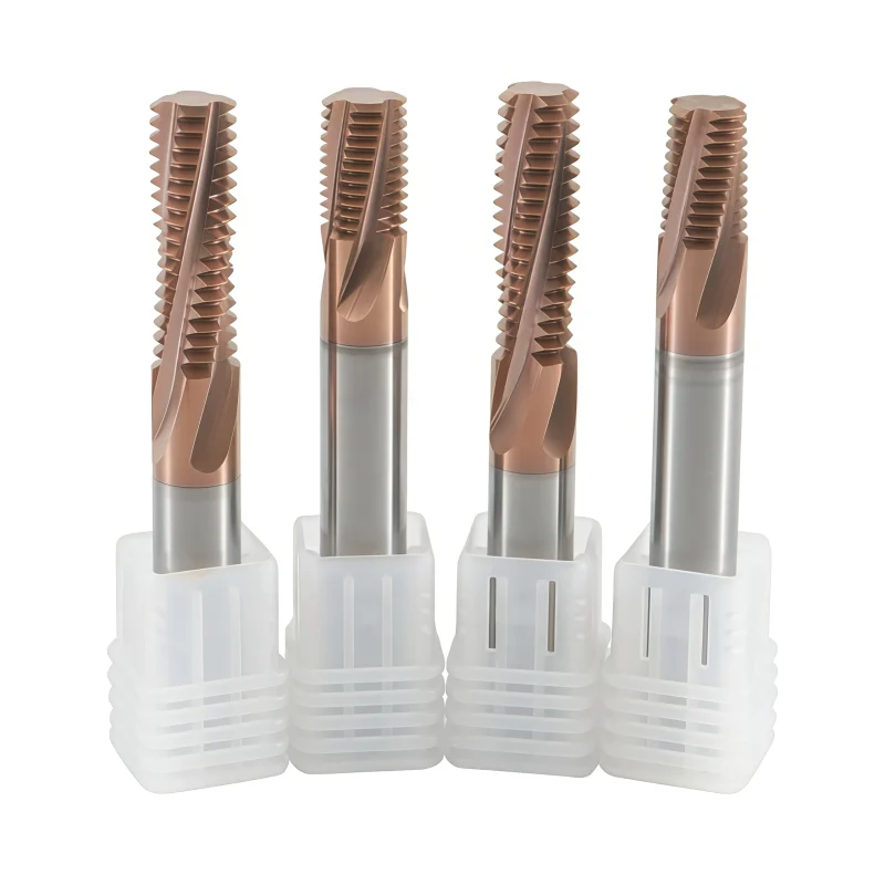
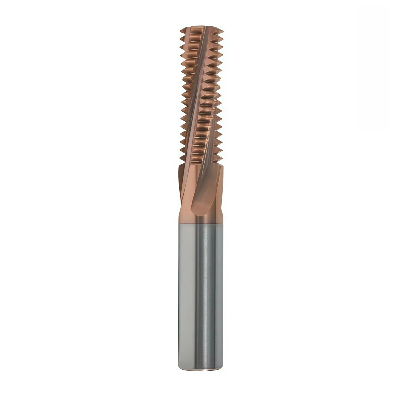
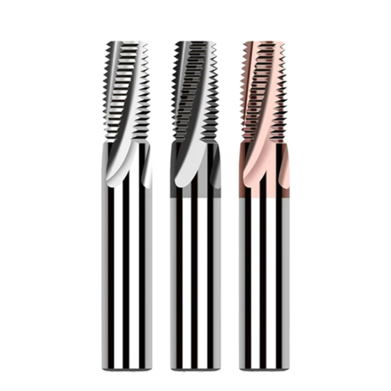
These solid carbide drill/thread mills combine core-hole generation and 60° internal thread milling without a separately pre-drilled pilot hole. The steel series covers M3–M12 with four-flute geometry and external or internal coolant by size. The DLC-coated series covers M1.6–M12 with two-, three- or four-flute designs for aluminum, copper and selected non-metallic materials. By completing multiple features with one tool and one clamping position, the series can reduce tool changes, setup time and accumulated positioning error in suitable CNC machining centers.
Key Configuration
Steel Machining Series
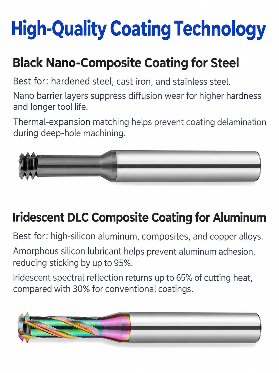
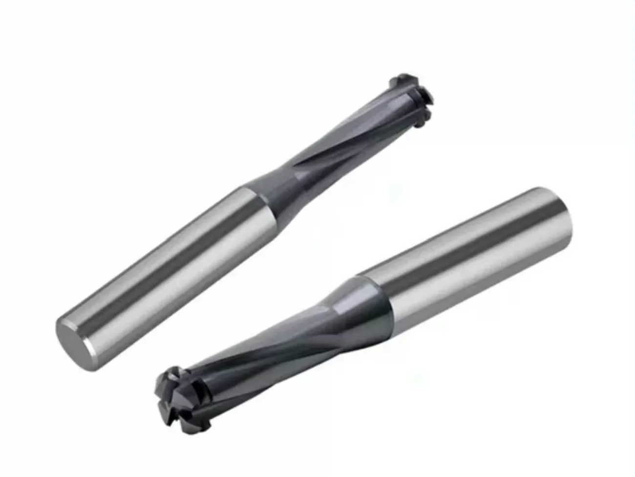
Four-flute solid carbide models for M3–M12. M3–M6 use external coolant; M8–M12 incorporate internal coolant to support chip evacuation at larger sizes and depths.
DLC-Coated Non-Ferrous Series
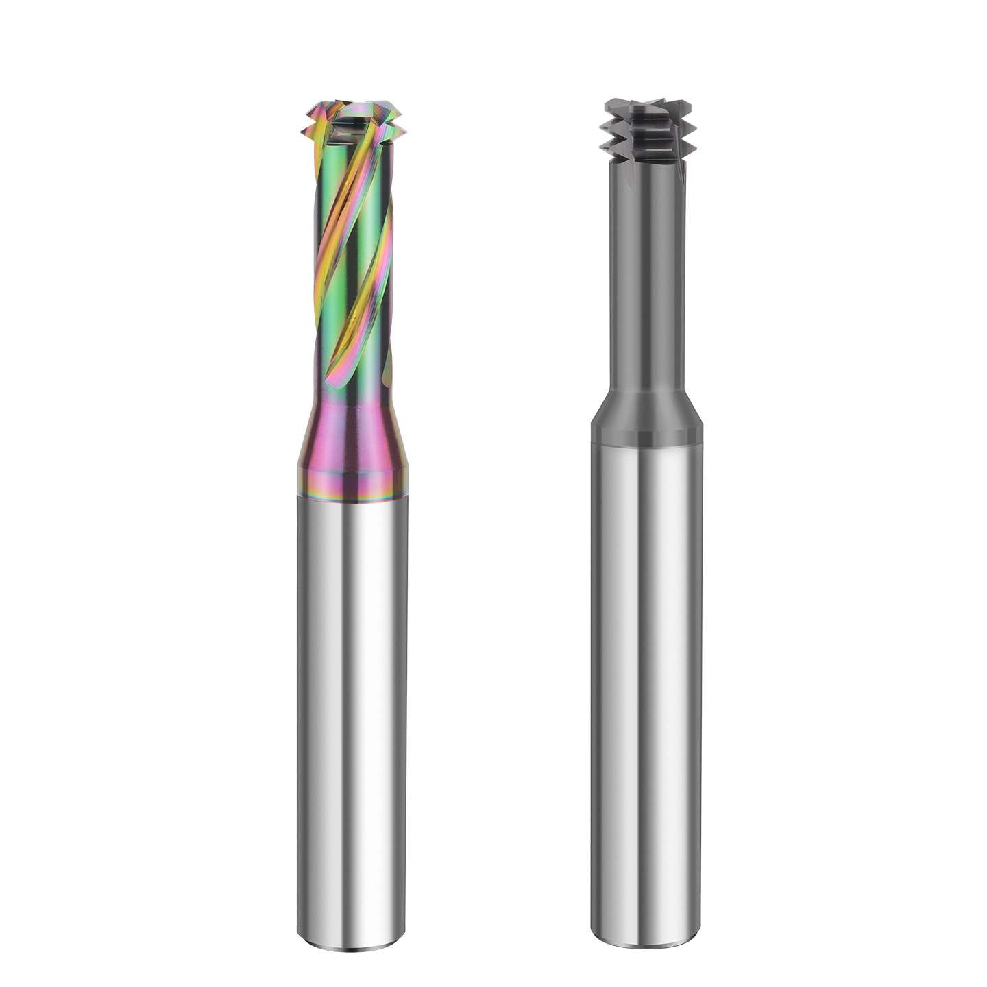
M1.6–M12 tools with two, three or four flutes. DLC coating and material-specific geometry support low-friction machining of aluminum, copper, plastics and acrylic.
Helical Interpolation Process
The tool follows a programmed orbital path to generate the core hole and thread. It should not be treated as a conventional axial drill unless the specific program and application are approved.
Key Product Advantages
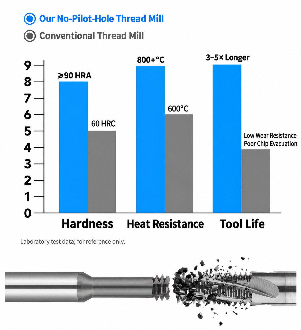
Combined Machining
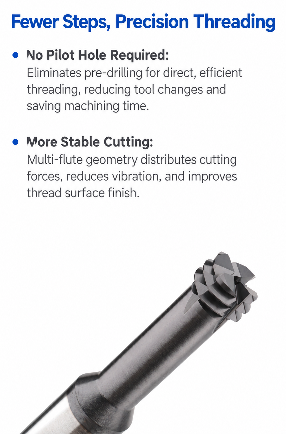
Generates the core hole and internal thread with one tool, eliminating a separate pilot-drilling tool in suitable applications.
Fewer Tool Changes
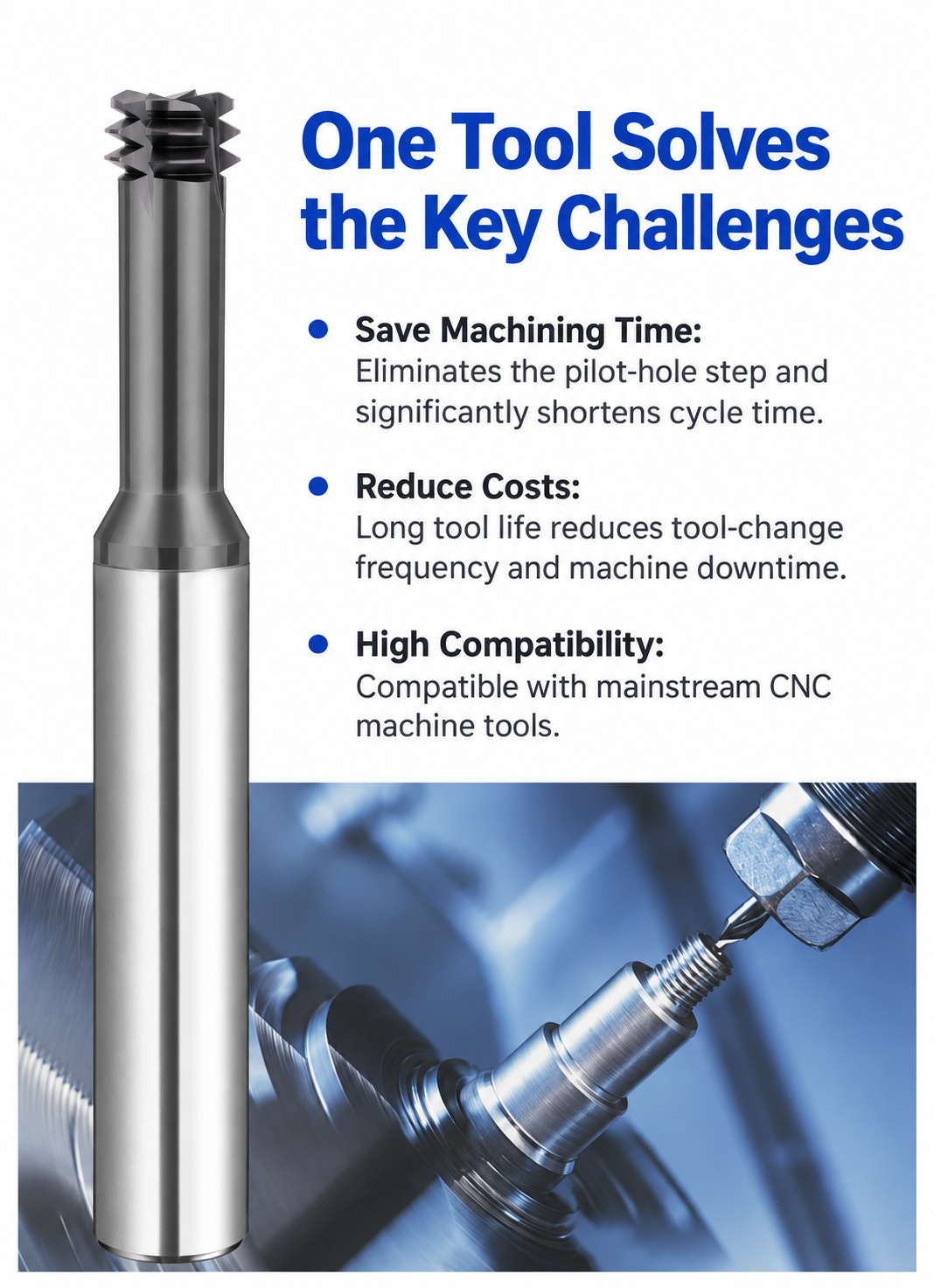
One combined tool can shorten tool-change time and simplify tool inventory for repeated threaded-hole production.
Material-Matched Versions
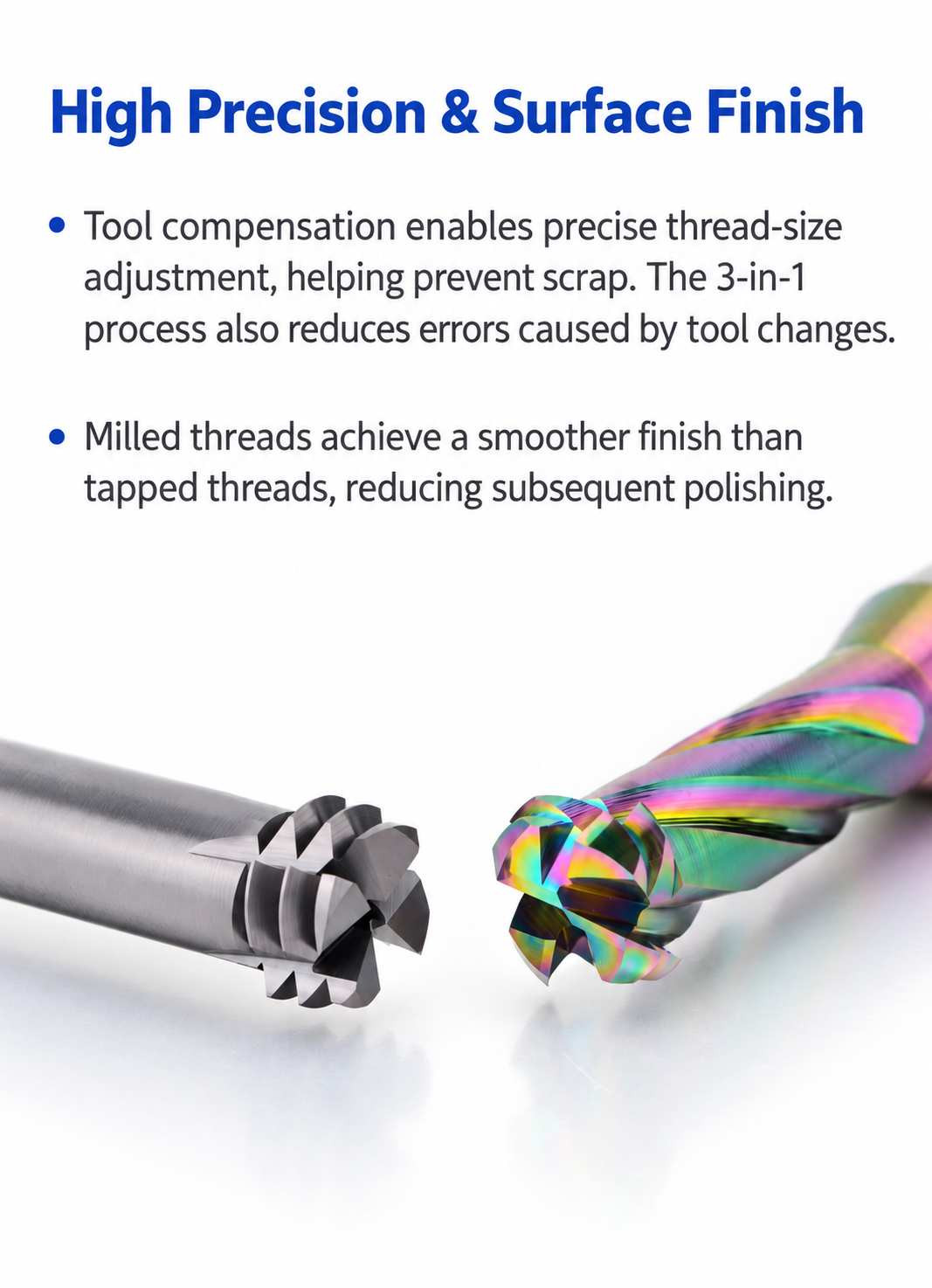
Separate steel and DLC-coated series match cutting geometry, flute count and coolant strategy to different material groups.
Controlled Thread Profile
Precision-ground 60° geometry supports repeatable metric internal threads when paired with the correct CNC toolpath and gauging.
Series Selection & Applications
| SERIES | STANDARD RANGE | RECOMMENDED MATERIALS | COOLANT / PROCESS |
|---|---|---|---|
| Steel Series | M3–M12 / P0.5–P1.75 | Carbon steel, alloy steel, pre-hardened steel; selected stainless-steel applications | External coolant M3–M6; internal coolant M8–M12 |
| DLC-Coated Series | M1.6–M12 / P0.35–P1.75 | Aluminum alloys, copper alloys, plastics and acrylic | Hole making + thread milling + programmed chamfering sequence shown in the catalog |
Machining Process Guidance
Product Geometry & Standard Size Ranges
The following charts show the material-specific geometry, size range, coolant configuration and recommended machining sequence.

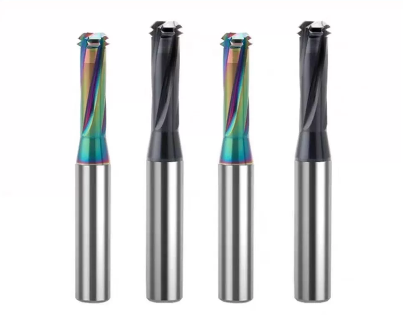 DLC-Coated Series — M1.6–M12 for Aluminum, Copper and Selected Non-Metallic Materials
Need help confirming material series, metric size, coolant configuration or CNC toolpath? Read our Thread Mill Selection Guide.
Tool Nomenclature & Dimensions
Reference dimensions and standard configurations for solid carbide no-pilot-hole drill/thread mills. All dimensions are in millimeters. The tool combines orbital core-hole generation and 60° internal thread milling; select the correct series according to material, thread size, coolant method and programmed operation sequence.
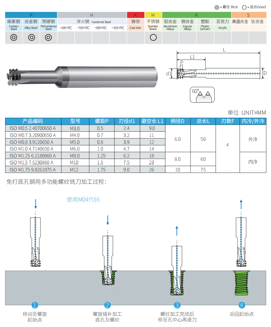 Steel Series: M3–M12 with four flutes and external / internal coolant options
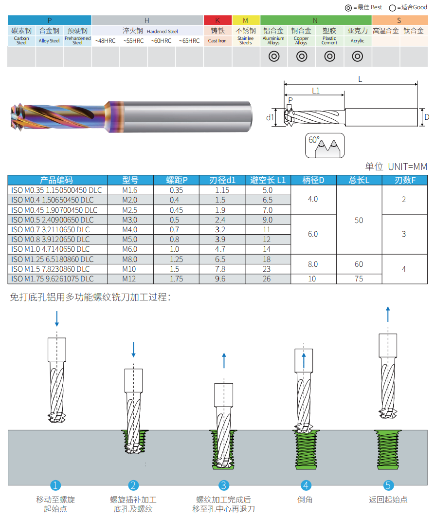 DLC-Coated Series: M1.6–M12 with two, three or four flutes
Technical Configuration
| PARAMETER | STEEL SERIES | DLC-COATED SERIES |
|---|---|---|
| Material da ferramenta | Fine-Grain Solid Carbide | Fine-Grain Solid Carbide + DLC Coating |
| Primary Materials | Carbon Steel / Alloy Steel / Pre-Hardened Steel | Aluminum / Copper / Plastics / Acrylic |
| Thread Profile | 60° Internal Metric | 60° Internal Metric |
| Standard Size | M3–M12 | M1.6–M12 |
| Pitch P | 0.5–1.75 | 0.35–1.75 |
| Cutter Diameter d1 | Ø2.4–Ø9.0 | Ø1.15–Ø9.6 |
| Clearance Length L1 | 9–26 | 5–26 |
| Shank Diameter D | Ø6 / Ø8 / Ø10 | Ø4 / Ø6 / Ø8 / Ø10 |
| Overall Length L | 50 / 60 / 75 | 50 / 60 / 75 |
| Flute Count F | 4 Flutes | 2 / 3 / 4 Flutes by Size |
| Líquido de arrefecimento | External M3–M6 / Internal M8–M12 | Not Specified in Source Chart; Confirm by Application |
Standard Steel Series Size Matrix
Four-flute models for steel machining. Coolant configuration changes from external to internal coolant at M8.
| PRODUCT CODE | SIZE | P | d1 | L1 | D | L | F | COOLANT |
|---|---|---|---|---|---|---|---|---|
| ISO M0.5 2.40700650 A | M3.0 | 0.5 | 2.4 | 9.0 | 6.0 | 50 | 4 | External |
| ISO M0.7 3.20900650 A | M4.0 | 0.7 | 3.2 | 11 | 6.0 | 50 | 4 | External |
| ISO M0.8 3.9120650 A | M5.0 | 0.8 | 3.9 | 12 | 6.0 | 50 | 4 | External |
| ISO M1.0 4.7140650 A | M6.0 | 1.0 | 4.7 | 14 | 6.0 | 50 | 4 | External |
| ISO M1.25 6.2180860 A | M8.0 | 1.25 | 6.2 | 18 | 8.0 | 60 | 4 | Internal |
| ISO M1.5 7.5230860 A | M10 | 1.5 | 7.5 | 23 | 8.0 | 60 | 4 | Internal |
| ISO M1.75 9.0261075 A | M12 | 1.75 | 9.0 | 26 | 10 | 75 | 4 | Internal |
Standard DLC-Coated Size Matrix
Material-specific models for aluminum, copper and selected non-metallic materials. Flute count increases with tool size.
| PRODUCT CODE | SIZE | P | d1 | L1 | D | L | F |
|---|---|---|---|---|---|---|---|
| ISO M0.35 1.150500450 DLC | M1.6 | 0.35 | 1.15 | 5.0 | 4.0 | 50 | 2 |
| ISO M0.4 1.50650450 DLC | M2.0 | 0.4 | 1.5 | 6.5 | 4.0 | 50 | 2 |
| ISO M0.45 1.90700450 DLC | M2.5 | 0.45 | 1.9 | 7.0 | 4.0 | 50 | 2 |
| ISO M0.5 2.40900650 DLC | M3.0 | 0.5 | 2.4 | 9.0 | 6.0 | 50 | 3 |
| ISO M0.7 3.2110650 DLC | M4.0 | 0.7 | 3.2 | 11 | 6.0 | 50 | 3 |
| ISO M0.8 3.9120650 DLC | M5.0 | 0.8 | 3.9 | 12 | 6.0 | 50 | 3 |
| ISO M1.0 4.7140650 DLC | M6.0 | 1.0 | 4.7 | 14 | 6.0 | 50 | 3 |
| ISO M1.25 6.5180860 DLC | M8.0 | 1.25 | 6.5 | 18 | 8.0 | 60 | 4 |
| ISO M1.5 7.8230860 DLC | M10 | 1.5 | 7.8 | 23 | 8.0 | 60 | 4 |
| ISO M1.75 9.6261075 DLC | M12 | 1.75 | 9.6 | 26 | 10 | 75 | 4 |
Machining Sequence
| STEP | STEEL SERIES | DLC-COATED SERIES |
|---|---|---|
| 01 | Move to the programmed helical start point | Move to the programmed helical start point |
| 02 | Helically interpolate to generate the core hole and thread | Helically interpolate to generate the core hole and thread |
| 03 | After threading, move to hole center and retract | After threading, move to hole center and retract |
| 04 | Return to the start position | Machine the programmed chamfer |
| 05 | — | Return to the start position |
How to Select a No-Pilot-Hole Thread Mill
- Match the Material: Use the steel series for the listed ferrous materials and the DLC series for aluminum, copper and the listed non-metallic materials.
- Match Size and Pitch: Select the exact metric size and P value from the appropriate matrix; these are dedicated-size tools.
- Check Feature Depth: Confirm L1 provides sufficient access while maintaining safe bottom and shoulder clearance.
- Confirm Coolant: Steel M8–M12 models require a machine and holder arrangement compatible with internal coolant delivery.
- Confirm CNC Capability: The control must support accurate helical interpolation and tool-center programming for the supplied machining sequence.
- Gauge the First Thread: Inspect the first completed feature and adjust compensation only in controlled increments.
Starting Cutting & Programming Guidance
The source charts do not provide numeric cutting data. Starting conditions must be confirmed for the exact tool code, material, coating, coolant method, feature depth, machine rigidity and holder runout.
| PARAMETER | CONTROL BASIS | STARTING GUIDANCE |
|---|---|---|
| Velocidade de corte | Material / coating / d1 | Use series-specific data; do not transfer steel data directly to the DLC series |
| Feed & Interpolation | Flute count / pitch / orbital diameter | Use the approved CNC program for the exact model and begin conservatively |
| Coolant & Chips | Material / depth / coolant style | Maintain chip evacuation and avoid recutting during the combined operation |
| Toolholding | Shank D / holder accuracy | Use a precision low-runout holder and minimum practical projection |
| Inspection | Thread gauge / hole depth / chamfer | Verify every feature produced by the combined cycle on the first component |
Thread Mill Selection Resources
For a custom size or application review, provide the complete thread callout, feature depth, workpiece material and hardness, machine model, holder, coolant method, inspection requirement and quantity.
No-Pilot-Hole Thread Mill Customization
Solid carbide no-pilot-hole thread mills combine core-hole generation and 60° internal metric thread milling in one CNC tool. Standard steel-cutting models cover M3–M12 with P0.5–P1.75, while DLC-coated models cover M1.6–M12 with P0.35–P1.75 for aluminium, copper and other non-ferrous materials. Geometry, coolant delivery, coating and dimensions can be reviewed for the workpiece material, thread depth, machine capability and finished-thread inspection requirement.
| PARAMETER | MANUFACTURING CAPABILITIES |
|---|---|
| Combined Cutting Function | Integrated bottom-cutting and 60° thread-milling geometry for producing the core hole and internal thread without a separate pilot-hole tool |
| Thread & Pitch Range | Steel series: M3–M12, P0.5–P1.75. DLC-coated non-ferrous series: M1.6–M12, P0.35–P1.75. Each tool is dedicated to the specified thread size and pitch |
| Cutter Diameter d1 | Steel series Ø2.4–Ø9.0 mm; DLC series Ø1.15–Ø9.6 mm. Custom diameter is reviewed against the thread size, core-hole generation and tool strength |
| Material Version | Steel geometry for carbon, alloy and pre-hardened steels, with selected stainless-steel applications; DLC-coated geometry for aluminium, copper, plastics and acrylic |
| Cutting / Reach Length L1 | Steel series 9–26 mm; DLC series 5–26 mm. Custom reach is reviewed against thread depth, bottom clearance, chip evacuation and rigidity |
| Shank Diameter D | Standard Ø4 / Ø6 / Ø8 / Ø10 mm cylindrical shanks according to model; custom shank dimensions can be reviewed for the selected holder |
| Overall Length L | Standard 50 / 60 / 75 mm according to thread size. Custom length is reviewed against machining depth, holder clearance and rigidity |
| Flute Count F | Steel series uses 4 flutes. DLC series uses 2 flutes for M1.6–M2.5, 3 flutes for M3–M6 and 4 flutes for M8–M12 |
| Coolant Delivery | Steel M3–M6 models use external coolant; steel M8–M12 models use internal coolant. DLC coolant strategy is confirmed according to material, machine and chip evacuation |
| Cutting-Edge Preparation | Edge preparation can be adjusted according to workpiece material, hardness, cutter diameter, interruption and expected cutting load |
| Coating Selection | Steel-application coating or edge treatment and low-friction DLC coating are selected separately; custom coating is reviewed against workpiece material and coolant conditions |
| Dimensional Tolerance | Drawing-defined requirements for the 60° profile, pitch, d1, L1, D, L, bottom-cutting geometry, shank accuracy, runout and other critical features can be reviewed before production |
Serviços de OEM e marca própria
OEM manufacturing and private-label supply are available for cutting-tool distributors, tooling brands and repeat-production customers. Steel or DLC series identification, product codes, metric size, pitch, coolant type, coating reference, labels and protective packaging can be configured according to the approved specification.

Laser Etching
Custom logos, product codes, Steel or DLC identification, metric size, pitch, coating reference and batch number can be marked according to the available shank area.
Custom Labels & Packaging
Individual protective tubes, model and pitch labels, color-coded series identification and private-label packaging can be prepared for distributor and OEM programs.
Commercial Terms
Standard tools can normally be dispatched in 1–2 working days. Minimum order is 10 pieces per size; custom samples and repeat supply are confirmed by specification.
Technical Workflow
A structured review process confirms the thread specification, combined cutting cycle, workpiece material, tool dimensions, flute configuration, coolant strategy and identification before standard, customized or private-label tools enter production.
Inquiry
Submit the metric thread size and pitch, thread depth, bottom clearance, material, machine capability, coolant method, coating and quantity.
Engineering
Review steel or DLC geometry, pitch, d1, L1, D, L, flute count, coolant delivery, carbide grade and coating.
Commercial
Confirm quotation, MOQ, sample conditions, production schedule, marking, packaging and delivery terms.
Production
Carbide preparation, CNC flute and profile grinding, edge preparation, coating and laser marking.
Quality Control
Inspect the 60° thread form, pitch, bottom-cutting geometry, dimensions, flute count, runout, coolant feature, coating and identification.
Quality, Inspection & Delivery
Our solid carbide no-pilot-hole thread mills are controlled through carbide material verification, precision CNC grinding, in-process measurement and final inspection. The integrated bottom-cutting geometry, 60° thread form, specified pitch, cutter diameter d1, reach L1, shank diameter D, overall length L, flute count F, coolant feature, radial runout, cutting-edge condition, coating appearance and identification are checked against the selected steel or DLC model or an approved custom drawing before packing.

Three-Stage Quality Control
Inspection checkpoints are arranged throughout production to support bottom-cutting geometry, thread-profile accuracy, pitch consistency, coolant-feature control and repeat-order traceability.
Incoming Material Control
Carbide substrate grade, blank diameter, blank length and supplied material information are checked against the confirmed tool specification.
In-Process Grinding Control
The integrated hole-making geometry, 60° thread profile, flute configuration, d1, L1, shank dimensions and applicable coolant feature are monitored during precision CNC grinding.
Final Tool Inspection
Finished tools are reviewed for product code, steel or DLC version, pitch, specified dimensions, runout, bottom and thread-cutting edges, coolant feature, coating, laser marking and packing labels.
Key Inspection Characteristics
Inspection requirements are confirmed according to the selected steel or DLC-coated standard model and the approved metric thread specification or custom drawing.
| INSPECTION ITEM | CONTROL FOCUS | CONFIRMATION BASIS |
|---|---|---|
| 60° Thread Form & Pitch | Included angle, thread-profile geometry, tooth spacing and specified metric pitch | Product code, thread callout and approved manufacturing specification |
| Cutter Diameter d1 | Cutting-section diameter and dimensional consistency | Standard size matrix or approved drawing |
| Bottom-Cutting Geometry | End-cutting edges, centre geometry, flute transitions and visible edge condition | Approved grinding specification and application version |
| Reach Length L1 | Cutting reach, flute length and shoulder position | Required thread depth, standard model or approved drawing |
| Shank Diameter D | Clamping diameter, cylindricity and surface condition | Applicable standard or custom shank requirement |
| Overall Length L | Total tool length and configuration consistency | Standard size matrix or approved drawing |
| Flute Count F | Steel-series 4-flute configuration or DLC-series 2 / 3 / 4-flute configuration, plus flute-to-flute consistency | Selected product code or custom specification |
| Deslocamento radial | Concentricity between the bottom-cutting section, thread-cutting section and shank | Agreed inspection requirement or approved drawing |
| Cutting Edge & Coating | Edge condition, visible defects, coating coverage and surface appearance | Application-specific edge-preparation and coating requirement |
| Marking & Identification | Tool code, steel or DLC series, metric size, pitch, coolant reference and batch information | Confirmed order and OEM packaging specification |
Measurement & Batch Traceability
Optical measuring systems, tool inspection equipment and appropriate dimensional gauges are selected according to the profile and feature being checked.
Optical Measurement
Profile and dimensional review of the integrated bottom-cutting geometry, 60° thread form, flute form and specified dimensions.
Runout Verification
Concentricity between the hole-making section, thread-cutting section and precision shank is reviewed to control radial runout.
Cutting-Edge Inspection
Magnified inspection checks cutting edges, rake and relief surfaces, transitions and visible grinding defects.
Batch Identification
Product code, steel or DLC designation, metric size, pitch, coolant type, dimensions, order and batch information can be linked for repeat supply.
Protective Packaging Process
Finished no-pilot-hole thread mills are individually protected to reduce contact with the precision-ground bottom and thread-cutting edges while keeping steel and DLC series, pitch, dimensions and batch identities clearly separated during storage and transportation.

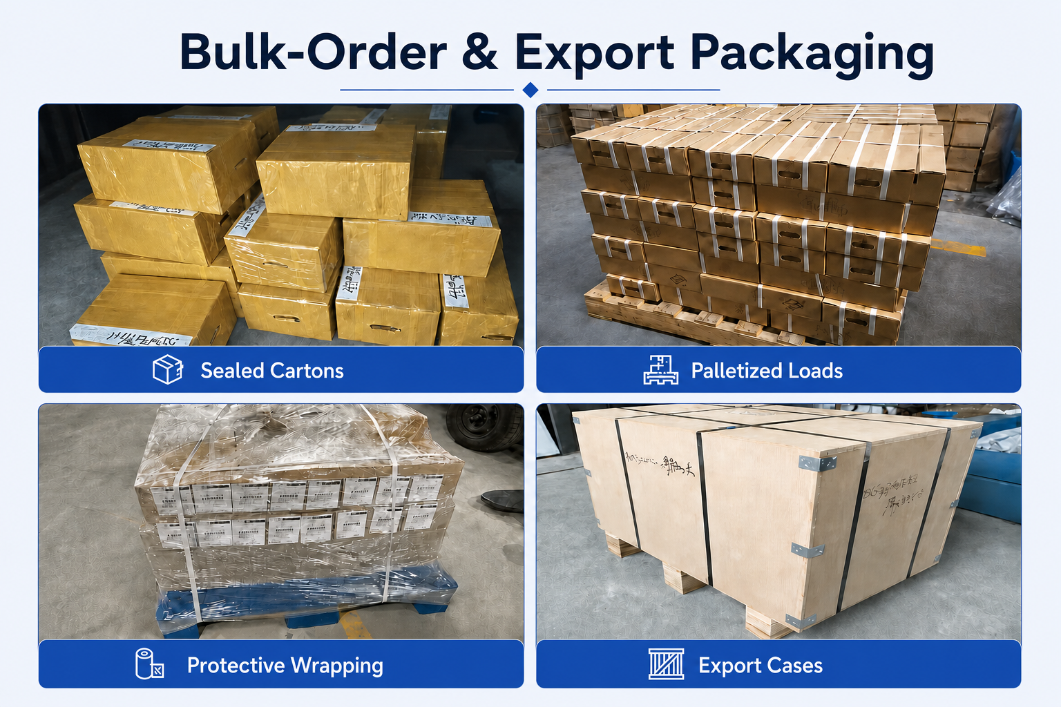
Bulk-Order & Export Packaging
Bulk orders of standard and custom no-pilot-hole thread mills can be arranged with steel and DLC-coated models separately labelled, together with reinforced cartons, protective wrapping, palletized loading or export cases according to quantity and transportation requirements.

Delivery Coordination
Production completion, inspection status, steel or DLC series identification, packing method and dispatch arrangements are checked against the approved order. In-stock standard tools can normally be dispatched within 1–2 working days. Minimum order is 10 pieces per size. Custom-tool lead time is confirmed after the thread specification, material version, combined cutting geometry, coolant method, dimensions, coating, quantity, inspection and packaging requirements are approved.
FAQ & Downloads
Review common selection, programming and ordering questions for solid carbide no-pilot-hole thread mills that combine core-hole generation and 60° internal metric thread milling in one CNC tool. Topics include steel and DLC versions, machine requirements, toolpath sequence, coolant, blind-hole use, thread inspection and customization.
Product & Application FAQs
Selection and application guidance for precision CNC thread milling.
What does “no pilot hole” mean for this thread mill?
It means the tool is designed to generate the core hole and mill the 60° internal thread in a combined CNC cycle, so a separate drilling operation is not required. This does not mean the tool can be fed like a conventional tap. It requires the programmed entry, helical interpolation, centre return and retraction sequence specified for this tool family.
What is the difference between the steel and DLC-coated versions?
The steel series is configured primarily for carbon steel, alloy steel and pre-hardened steel, with selected stainless-steel applications. It covers M3–M12 and uses four flutes. The low-friction DLC series is intended for aluminium, copper and suitable non-ferrous or non-metallic materials; it covers M1.6–M12 and uses two, three or four flutes according to size. Select the version by workpiece material rather than coating colour alone.
How do I select the correct product code?
Start with the workpiece material, exact metric thread size, pitch and required thread depth. Then match the dedicated standard model and confirm cutter diameter d1, cutting length L1, shank diameter D, overall length L, flute count and coolant type. Also confirm bottom clearance, holder access and whether the machine can execute the required helical interpolation cycle.
Can one tool produce different thread sizes or pitches?
No. Each standard tool code is matched to a specific metric thread size and pitch because the tool must generate both the core hole and the finished thread geometry. Choose the exact model shown in the dimensional table. A different diameter or pitch requires another standard code or an approved custom design.
Can this thread mill be used in blind holes?
Yes. Blind-hole machining is a primary application, provided the programmed depth leaves adequate bottom clearance and the toolpath supports chip evacuation. Confirm L1, entry position, centre-return movement, coolant delivery and retraction before machining. Avoid contact between the tool shoulder or shank and the workpiece surface.
What materials can the standard series machine?
The steel series is recommended for carbon steel, alloy steel and pre-hardened steel and can be applied to selected stainless steels after confirming cutting conditions. The DLC series is recommended for aluminium and copper and can also be reviewed for plastics and acrylic. Do not use the DLC version for ferrous materials unless the application has been specifically approved.
How should the toolpath and finished thread be controlled?
Use the approved CNC cycle for the selected model: position at the helical start point, interpolate to generate the core hole and thread, return to the hole centre and retract. The DLC process chart also includes a chamfering step before returning to the start point. Use a precision low-runout holder and verify the first finished thread with the correct plug gauge before batch production.
Ordering & Customization FAQs
Information for distributors, tooling brands and customers sourcing standard or custom solid carbide thread mills.
What standard sizes are available?
The steel series covers M3–M12, P0.5–P1.75, d1 Ø2.4–Ø9.0 mm, L1 9–26 mm, Ø6 / Ø8 / Ø10 mm shanks and 50 / 60 / 75 mm overall lengths. The DLC series covers M1.6–M12, P0.35–P1.75, d1 Ø1.15–Ø9.6 mm, L1 5–26 mm, Ø4 / Ø6 / Ø8 / Ø10 mm shanks and 50 / 60 / 75 mm overall lengths.
Can you manufacture a custom no-pilot-hole thread mill?
Yes. Custom metric size, pitch, cutter diameter d1, reach L1, shank diameter D, overall length L, flute configuration, bottom-cutting geometry, coolant delivery, carbide grade, edge preparation and coating can be reviewed. Please provide the complete thread callout, component drawing, thread depth, bottom clearance, material, machine and holder restrictions, inspection requirement and quantity.
Are OEM marking, custom coatings and private-label packaging available?
Yes. Laser marking can include the customer logo, product code, steel or DLC designation, metric size, pitch, coating code and batch number. Application-specific coatings, custom labels, protective tubes and private-label packaging can also be reviewed for distributor and OEM programs.
What are the MOQ and lead time?
The minimum order is 10 pieces per size. In-stock standard tools can normally be dispatched within 1–2 working days. Custom-tool lead time is confirmed after the thread specification, steel or DLC version, combined cutting geometry, coolant delivery, dimensions, carbide grade, coating, quantity, inspection requirements, laser marking and packaging are approved.
Technical Downloads
Access solid carbide no-pilot-hole thread-mill references for material-version selection, dimensional review and CNC machining preparation.
Catálogo de fresas de rosca de metal duro maciço
Thread-mill families, thread standards, pitch ranges, dimensional configurations and application references.
Carbide Tool Speeds & Feeds Guide
General starting cutting-data references and adjustment guidance for carbide threading applications.
Starting data should be confirmed according to steel or DLC geometry, cutter diameter, pitch, workpiece material and hardness, coating, thread depth, coolant delivery, holder runout and machine rigidity. Verify the first completed thread with the correct gauge before batch production.
Related Guides & Thread Mill Resources
Explore practical selection guides and related solid carbide thread mill series for different standards, materials and machining requirements.
Selection guidance for thread standards, pitch, tool style, diameter, depth and workpiece material.
Compare flexibility, thread size range, breakage risk and typical machining applications.
Browse metric, Unified, pipe-thread, single-form, full-profile and material-specific thread mill series.
Need Sizes, Pricing or Custom Options?
Send us the required tool type, sizes, quantities, workpiece material and any OEM or custom requirements. We will confirm suitable specifications, availability, lead time and quotation details.
Drawings, size lists and reference photos are welcome.