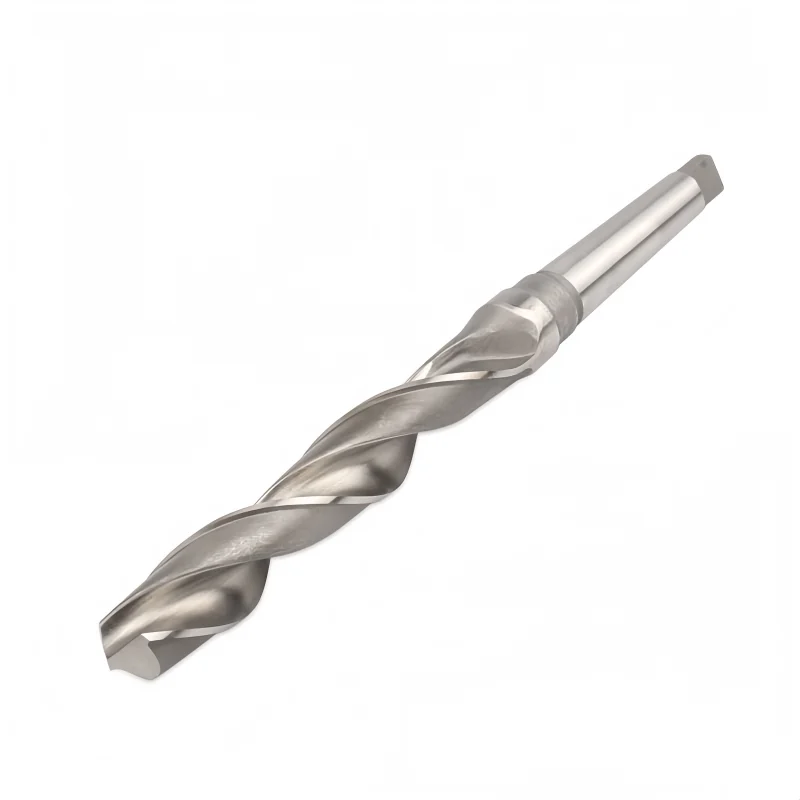

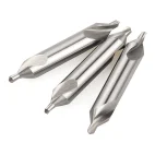


M2 HSS Center Drill Bits
Double-ended Type A center drill bits for center-hole preparation and controlled hole starting. The supplied chart lists 12 cutting diameters from 1.0 to 10 mm, with matching shank diameters and overall lengths. Specify M2 HSS and confirm the required point profile and finish when ordering.
Product Specifications
Consistent Quality
Consistent geometry across repeat orders.
Flexible Orders
Small batches and mixed sizes available.
OEM Support
Custom marking, labels and packaging.
Standard & Custom
Standard sizes and custom configurations.
M2 HSS Center Drill Bits Overview
These Type A, double-ended center drills are intended for making center holes in workpieces held between centers and for controlled hole-starting operations. The supplied dimension chart lists 12 cutting diameters from 1.0 to 10 mm, with matching shank diameters of 4–25 mm and overall lengths of 35.5–100 mm. The product title specifies M2 high-speed steel; confirm the grade, point geometry and finish for the ordered model, because the older product description lists several alternative steel grades and surface treatments.
Key Configuration
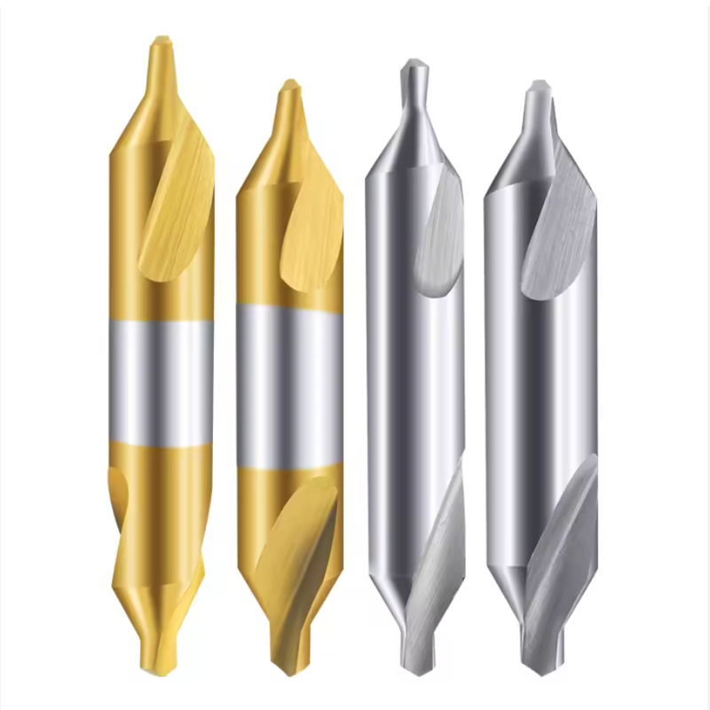
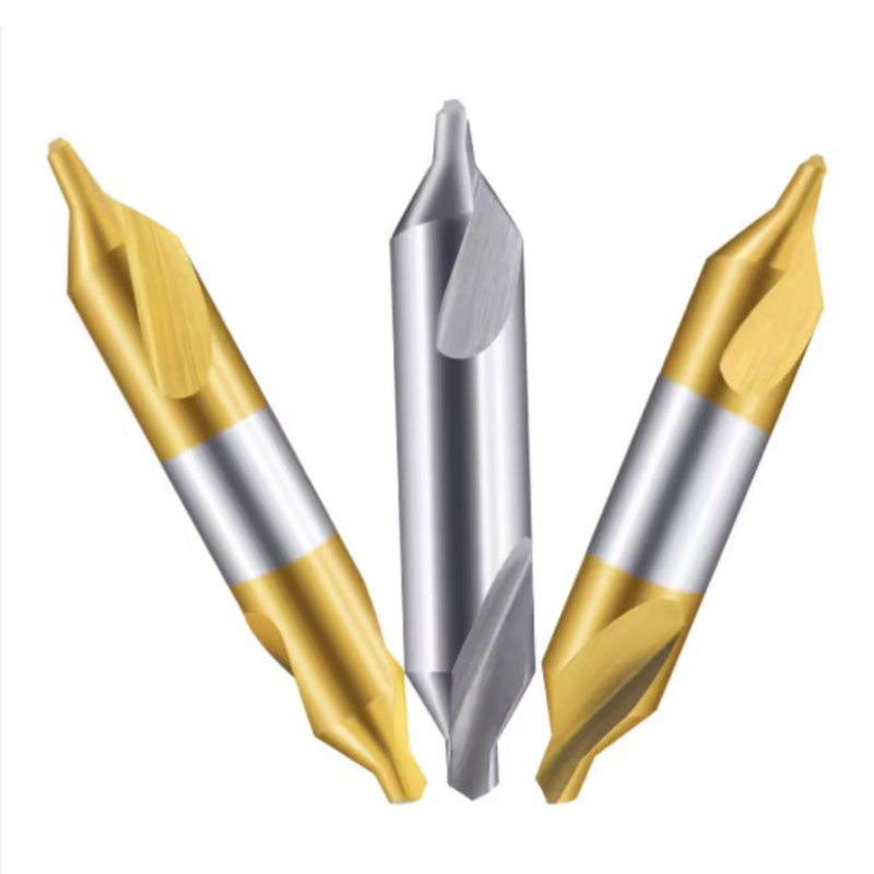
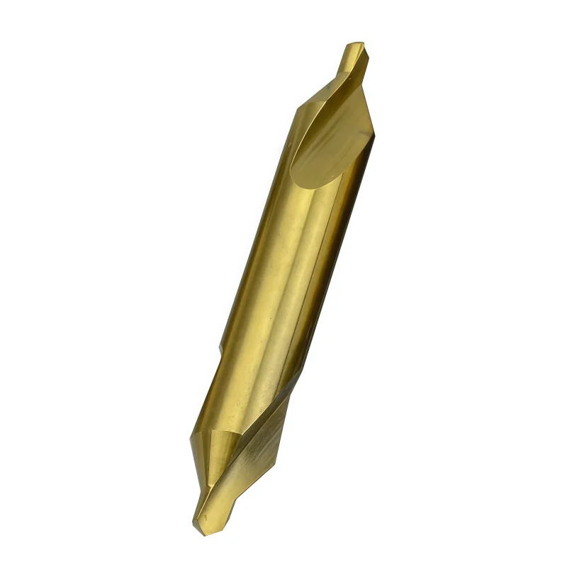
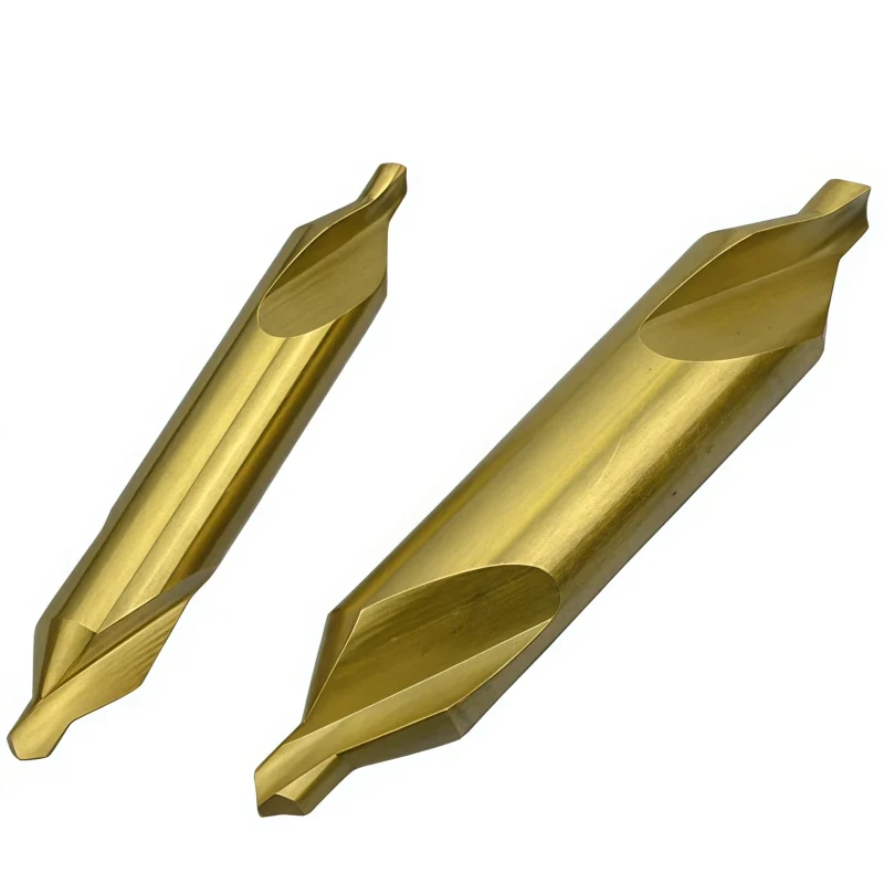
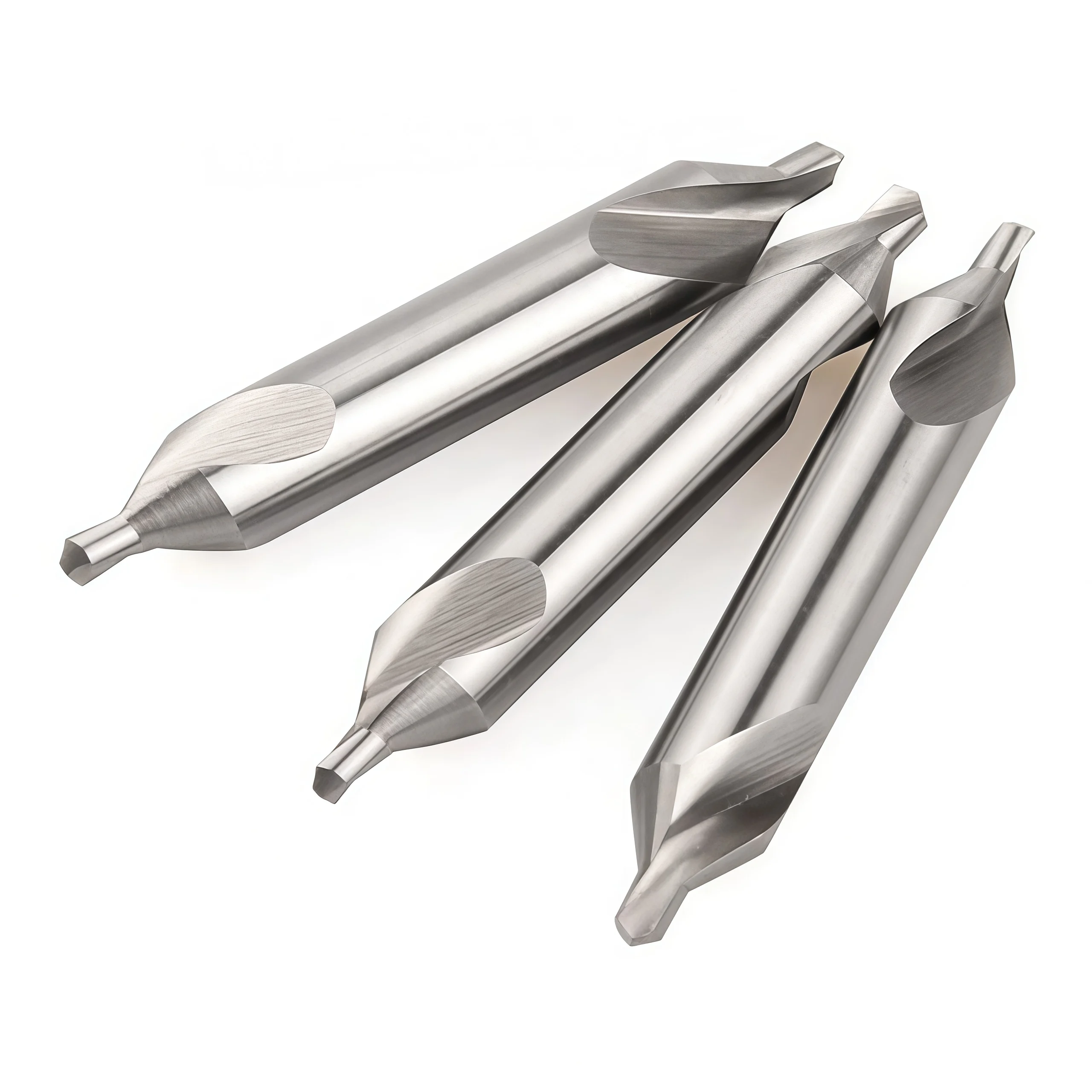
The illustrated form has a pilot and countersink on each end. Confirm the specified included angle and center-hole standard for the ordered model.
Both ends are shown as usable. Protect the unused end in the holder and verify adequate grip and clearance before machining.
Each cutting diameter has a corresponding shank diameter and overall length in the 12-size chart. Check holder fit before ordering.
Key Product Advantages
Center-Hole Preparation
Creates a center feature for workpieces machined between centers.
Double-Ended Design
Allows the second end to be used after the first end wears, if the tool remains serviceable.
12 Listed Sizes
Cutting diameters from 1.0 to 10 mm, each with specified shank and overall dimensions.
Grade and Finish Options
Confirm M2 grade and the requested finish; other grades and coatings belong to separate options.
Centering Applications
Use the center drill to prepare center holes in turned parts or to establish a controlled starting location where the subsequent drilling process requires it. The supplied product image lists carbon steel, 45# steel, die steel and aluminum alloy as example workpieces. Select cutting data and coolant for the exact material grade, machine rigidity and tool configuration.
Workpiece Material Selection
The source image names carbon steel, 45# steel, die steel and aluminum alloy as examples, without defining workpiece hardness or tool-specific cutting data. Provide the exact grade, hardness and center-hole requirement when selecting the M2 tool, finish and coolant strategy.
Product Details & Available Configurations
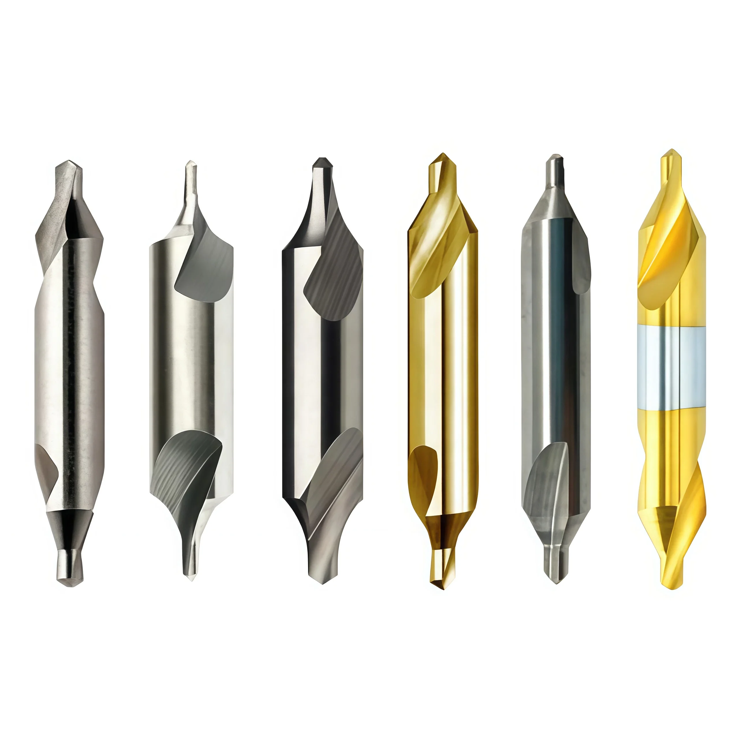
The following images are retained from the original product page. They may show different finishes or related variants; confirm the exact M2 grade, point profile, coating and size in the quotation.


*The dimension image identifies the tool as HSS but does not verify its exact steel grade. Confirm M2/6542 for the ordered variant. Gold-colored product photos do not establish a specific coating.
Size Chart & Specifications
The supplied Type A center drill chart lists 12 cutting diameters (D) from 1.0 to 10 mm. Corresponding shank diameters (d) range from 4 to 25 mm and overall lengths (L) from 35.5 to 100 mm. All values are in millimeters. Select the complete D × d × L combination, then check holder fit and the required center-hole form.
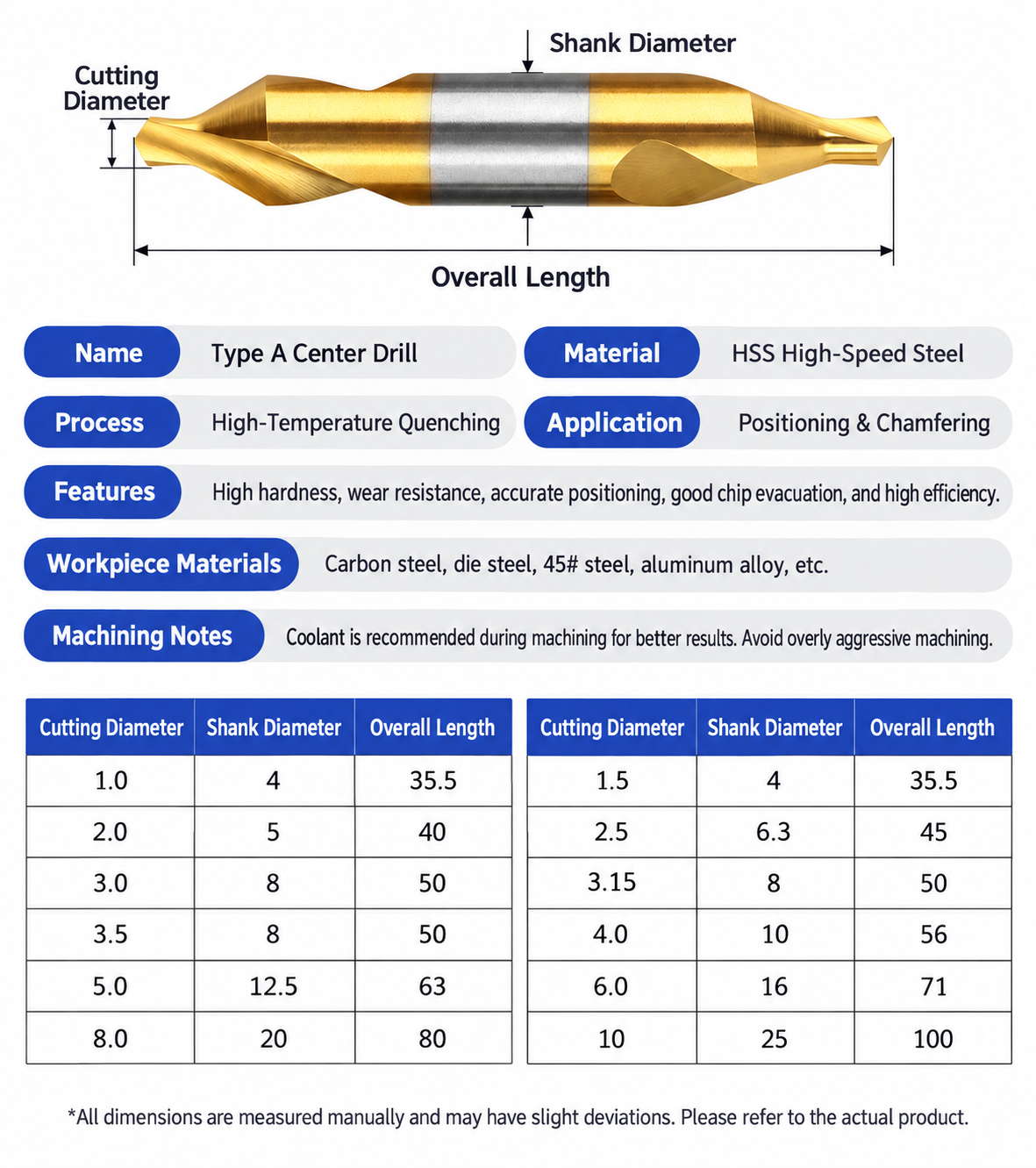
| Cutting D (mm) | Shank d (mm) | Overall L (mm) | Cutting D (mm) | Shank d (mm) | Overall L (mm) |
|---|---|---|---|---|---|
| 1.0 | 4 | 35.5 | 3.5 | 8 | 50 |
| 1.5 | 4 | 35.5 | 4.0 | 10 | 56 |
| 2.0 | 5 | 40 | 5.0 | 12.5 | 63 |
| 2.5 | 6.3 | 45 | 6.0 | 16 | 71 |
| 3.0 | 8 | 50 | 8.0 | 20 | 80 |
| 3.15 | 8 | 50 | 10 | 25 | 100 |
Specification confirmation: The current image states Type A and HSS. The older page lists M2/6542 alongside HSS4241, HSS4341, M35 and carbide options, and gives a wider 0.5–12.5 mm size range. This page uses the 12 sizes actually shown in the supplied chart; confirm M2/6542, DIN 333 Form A, point angle and finish for the ordered variant. Do not assume TiN or AlTiN coating from a gold-colored illustration.
HSS Center Drill Speeds & Feed Settings
The supplied dimension chart does not provide validated cutting data. Select a starting speed and feed for the confirmed M2 tool, cutting diameter, center-hole depth, workpiece grade and coolant conditions. The RPM, hole-life and accuracy figures in the older description are not specifications for this 12-size chart.
Setting Speed & Feed
Spindle speed: n = (1000 × Vc) / (π × D), where n is RPM, Vc is cutting speed in m/min and D is the cutting diameter in mm used for the selected tool-specific recommendation.
Feed rate: F = n × f, where F is feed in mm/min and f is feed per revolution in mm/rev.
Calculation example: At 800 RPM and 0.02 mm/rev, programmed feed is 16 mm/min. This illustrates the calculation only; it is not a material-specific recommendation.
For general reference, see our HSS cutting tools speeds & feeds guide. Confirm tool-specific settings for center drilling.
HSS Drill Customization & OEM
HSS drills can be reviewed against your hole requirements, workpiece material and machine setup. We can discuss application-specific dimensions, cutting geometry, tool material, surface finish and private-label presentation. Available options depend on the drill type and the confirmed manufacturing specification.
Point & Cutting Geometry
Review point angle, point thinning, flute design and cutting-edge geometry according to the workpiece and drilling operation. Geometry options vary between twist drills, center drills and special drills.
Dimensions & Shank
Specify cutting diameter, flute length, overall length and the required shank configuration. Straight-shank, Morse-taper, extra-long and other constructions are reviewed by product series.
Finish & OEM Branding
Review a suitable coating or surface finish where applicable. Laser marking, labels and packaging can be discussed for distributor and private-label orders.
Customization Options
| Parameter | Information to Confirm |
|---|---|
| Drill Type | Twist drill, center drill, extra-long drill or application-specific design |
| Tool Material | Required HSS grade, such as M2, M35 or M42, subject to the selected series |
| Diameter | Cutting diameter and required diameter tolerance |
| Length & Reach | Flute length, overall length, drilling depth and clearance requirements |
| Point & Flutes | Point geometry, flute design and chip-evacuation requirements |
| Shank | Shank type and dimensions required by the holder |
| Surface Finish | Uncoated, coated or treated finish, where suitable for the tool and application |
| OEM Presentation | Tool marking, product labels and packaging requirements |
Options are reviewed for the specific product and order. A listed option does not imply that every HSS drill series has the same material, geometry, shank or coating choices.
What to Send for a Custom Drill Quote
Send the drill type, diameter, hole depth, workpiece grade, required geometry, shank or holder details, quantity and any coating or marking requirements. A drawing or reference sample helps confirm non-standard dimensions.
Submit a Custom Tool RequestHSS Drill Quality Control

HSS drills are reviewed against the confirmed product specification or approved drawing. Checks are selected according to drill type, size, geometry and finish, from incoming material through grinding, final inspection and packing.
Material Verification
Check the specified HSS grade and incoming material information against the production order.
In-Process Checks
Review key dimensions and ground features during production so deviations can be addressed before final inspection.
Final Tool Inspection
Check the applicable diameter, lengths, point geometry, cutting edges and shank against the approved specification.
Marking & Packing
Verify the model identification, order quantity and agreed packaging before dispatch.
Inspection Checkpoints
| Feature | Check Against the Confirmed Specification |
|---|---|
| Cutting Diameter | Nominal size and specified diameter tolerance |
| Flute & Overall Length | Required cutting length, tool reach and overall dimension |
| Point Geometry | Point angle, symmetry and specified point features |
| Cutting Edges & Flutes | Visible edge condition and the relevant ground flute features |
| Shank & Finish | Specified shank dimensions and applicable coating or surface finish |
| Order Identification | Model, size, quantity, marking and agreed packaging |
 Learn more about our manufacturing and quality process.
Product FAQs
What sizes are listed for these center drills?
The supplied chart lists 12 cutting diameters from 1.0 to 10 mm. Their corresponding shank diameters range from 4 to 25 mm and overall lengths from 35.5 to 100 mm. Select the complete cutting diameter, shank diameter and overall length combination from the Specifications table.
What is a Type A center drill used for?
A Type A center drill prepares a center hole for workpieces machined between centers. It may also be used to establish a controlled starting location for a following drilling operation when its geometry matches the required hole. Confirm the center-hole form and angle against the part drawing.
Can both ends of the drill be used?
The illustrated drill has cutting features at both ends. The second end can be used if the tool remains serviceable. Protect the unused end during clamping, and confirm that the holder provides sufficient grip and clearance.
Are the listed drills all confirmed as M2 HSS?
M2 HSS is specified in this product title. The supplied dimension image identifies the tool as HSS but does not state an exact steel grade, while the older product description lists several material options. Confirm M2/6542 for each ordered size in the quotation or approved specification.
Do the gold-colored images mean these drills are TiN coated?
No coating is assigned to the 12 sizes in the dimension chart. The older product page mentions bright, amber, TiN and AlTiN options, but image color alone does not identify the finish. Specify the required surface treatment when requesting a quotation.
What cutting speed and feed should I use?
The dimension chart does not give validated cutting data. Choose starting parameters for the confirmed M2 grade, cutting diameter, workpiece material, center-hole depth, machine rigidity and coolant setup. Avoid overloading the small pilot and verify the results on a trial part.
Ordering & OEM FAQs
What information should I provide for a quotation?
Send the cutting diameter, required quantity per size, workpiece material and center-hole drawing or standard. Include the required M2 grade, point angle, shank diameter, overall length, finish and any packaging or marking requirements.
Can other sizes or configurations be supplied?
The current chart confirms 12 listed size combinations. If you need another cutting diameter, shank size, overall length, center-hole form, steel grade or coating, send a drawing for feasibility review. Available options, tolerances, MOQ and lead time will be confirmed for the requested configuration.
Can I combine several sizes in one order?
Send a size-by-size quantity list for a mixed-size quotation. Stock availability, minimum quantity and dispatch timing will be confirmed for each selected specification.
Downloads & Technical Reference
For general calculations, see the HSS cutting tools speeds & feeds guide. Confirm tool-specific settings for center drilling before production.
Need Sizes, Pricing or Custom Options?
Send us the required tool type, sizes, quantities, workpiece material and any OEM or custom requirements. We will confirm suitable specifications, availability, lead time and quotation details.
Drawings, size lists and reference photos are welcome.