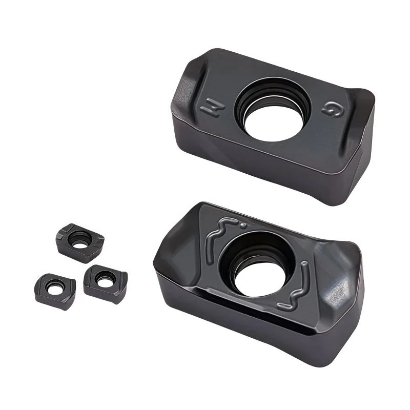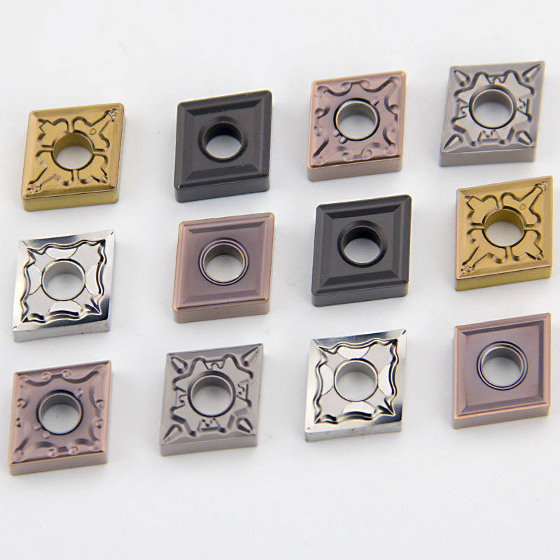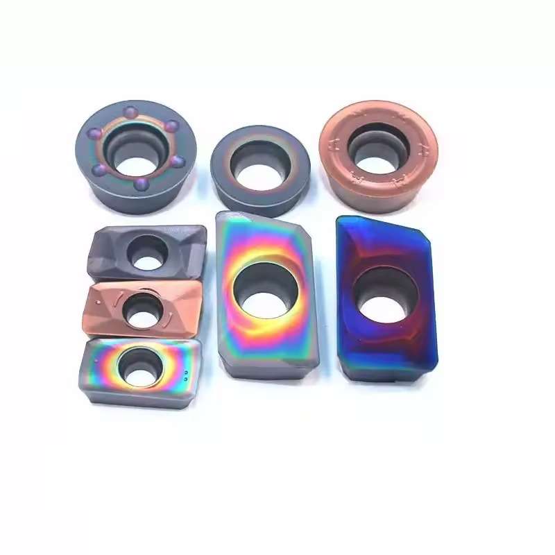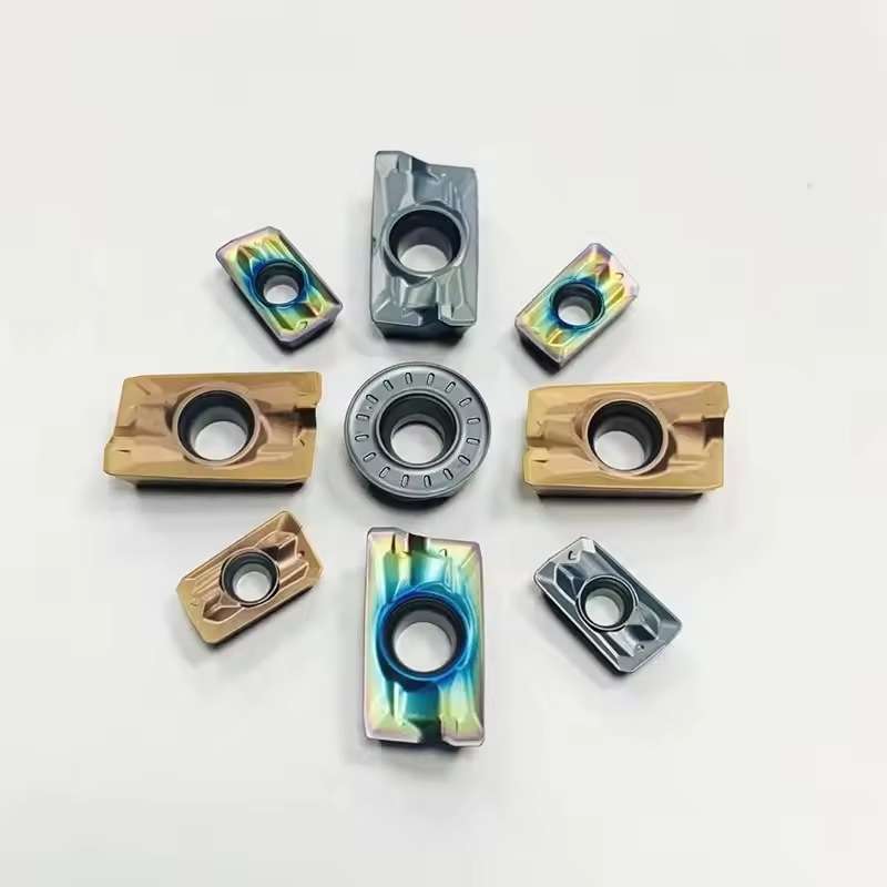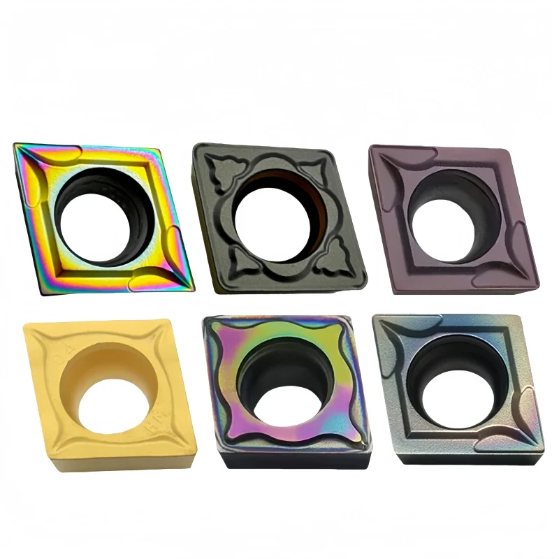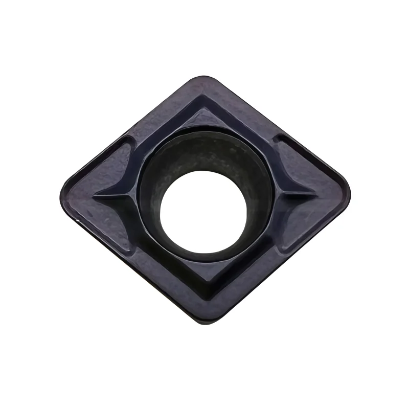
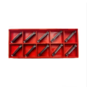
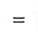
MGMN300-04-T KP2500 PVD-Coated Carbide Grooving Insert for Parting and Grooving
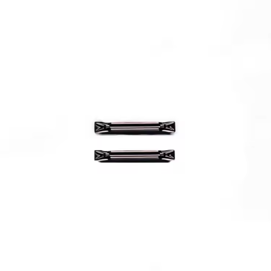
MGMN300-04-T KP2500 PVD-coated carbide inserts are designed for 3 mm grooving and parting operations in steel and stainless steel. The T-type chip-forming geometry supports chip control and cutting-edge stability, while the wear-resistant coating improves consistency during repeat production. Matching holders and related groove widths can be supplied by confirmation.
Consistent Quality
Consistent geometry across repeat orders.
유연한 주문
Small batches and mixed sizes available.
OEM Support
Custom marking, labels and packaging.
표준 및 맞춤형
Standard sizes and custom configurations.
◆제품 개요
그리고 MGMN300-04-T KP2500 PVD-coated carbide grooving insert is developed for external grooving and parting operations where controlled chip formation, edge security, and repeatable groove width are required. Its nominal 3.0 mm cutting-width class makes it suitable for CNC lathe work involving steel and selected stainless-steel components, provided that the insert, holder pocket, cutting data, coolant delivery, and workpiece condition are correctly matched.
Grooving performance depends on more than insert color or width. The holder interface, chipbreaker, grade, coating, edge preparation, workpiece material, and overhang must be evaluated together. For a broader explanation of insert codes and material groups, see our
carbide insert types and selection guide.
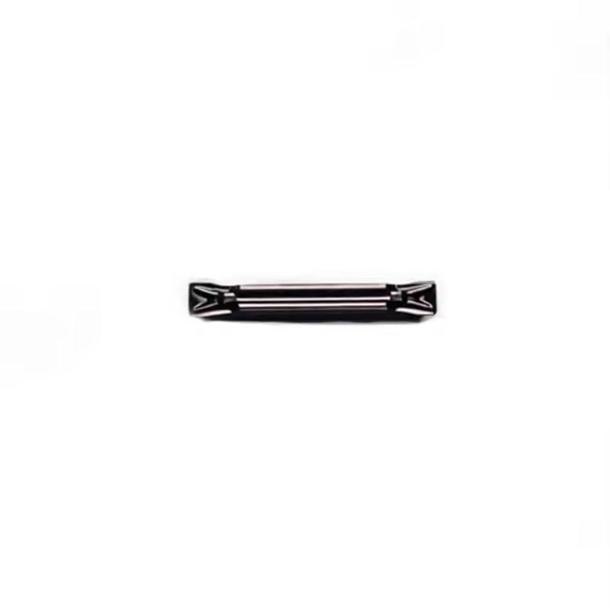
◆Designed for Grooving and Parting
The same insert may be used in different radial operations, but setup requirements change with groove depth, component diameter, wall thickness, and whether the cut reaches the centerline.
External Grooving
Produces controlled radial grooves with a nominal 3.0 mm width class. The tool should be aligned perpendicular to the workpiece axis to reduce tapered groove walls and uneven flank wear.
Parting Off
Separates a finished component from bar stock. Tool overhang should be kept as short as practical, with secure clamping and coolant directed into the cutting zone for chip evacuation.
Groove Widening
Wider recesses may require multiple radial plunges or controlled lateral movement. Confirm that the chipbreaker and holder are approved for the intended side load before programming axial movement.
For general external turning, facing, profiling, and other insert shapes, compare our
carbide turning and milling insert range.
◆Performance Features
Controlled Chip Formation
The molded top geometry is intended to curl and narrow the chip within its recommended feed and depth range, helping reduce chip entanglement around the workpiece.
PVD-Coated Cutting Edge
The PVD coating supports wear resistance while retaining a comparatively sharp cutting edge, useful where cutting-force control and edge integrity are both important.
Double-Ended Economy
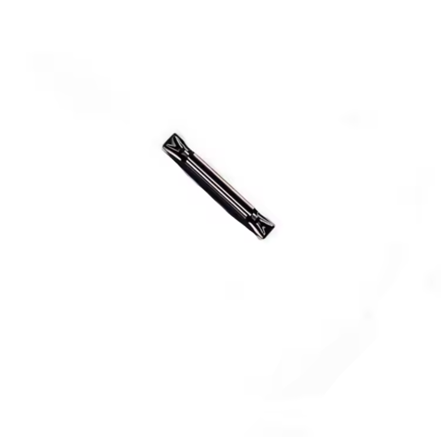
The MGMN-style body provides two usable cutting ends when both ends remain undamaged and the insert is indexed in a clean, compatible holder pocket.
Stable Groove Width
A dedicated 3.0 mm width class supports repeatable groove production when tool alignment, pocket condition, runout, deflection, and cutting-edge wear are controlled.
◆Understanding the Product Code
| Code Element | Practical Meaning | What to Confirm |
|---|---|---|
| MGMN | MGMN-style double-ended grooving and parting insert family | Holder series, insert seat, clamping method, hand, and maximum cutting depth |
| 300 | Nominal 3.0 mm cutting-width class | Actual tolerance, groove specification, corner treatment, and mating holder |
| 04-T | Supplier-specific geometry or chipbreaker designation | Do not replace by width alone; compare the complete code and top geometry |
| KP2500 | Carbide substrate and PVD-coating grade designation | Material group, hardness, interrupted-cut level, coolant, and cutting conditions |
◆Material and Grade Matching
KP2500 Application Focus
- ◆Steel: suitable as the primary application group when speed, feed, rigidity, and coolant are matched.
- ◆Stainless steel: use stable feed and effective coolant delivery to reduce rubbing, adhesion, and work hardening.
- ◆Hardened workpieces: application near HRC45–55 requires process validation and a rigid machine-tool-workpiece system.
- ◆Interrupted cuts: reduce shock and verify edge toughness before increasing productivity.
Stainless steel can generate high heat and work-harden when the insert rubs instead of cutting. Review our
stainless-steel machining and heat-control guide
before establishing production parameters.
◆Grooving Insert Family Reference
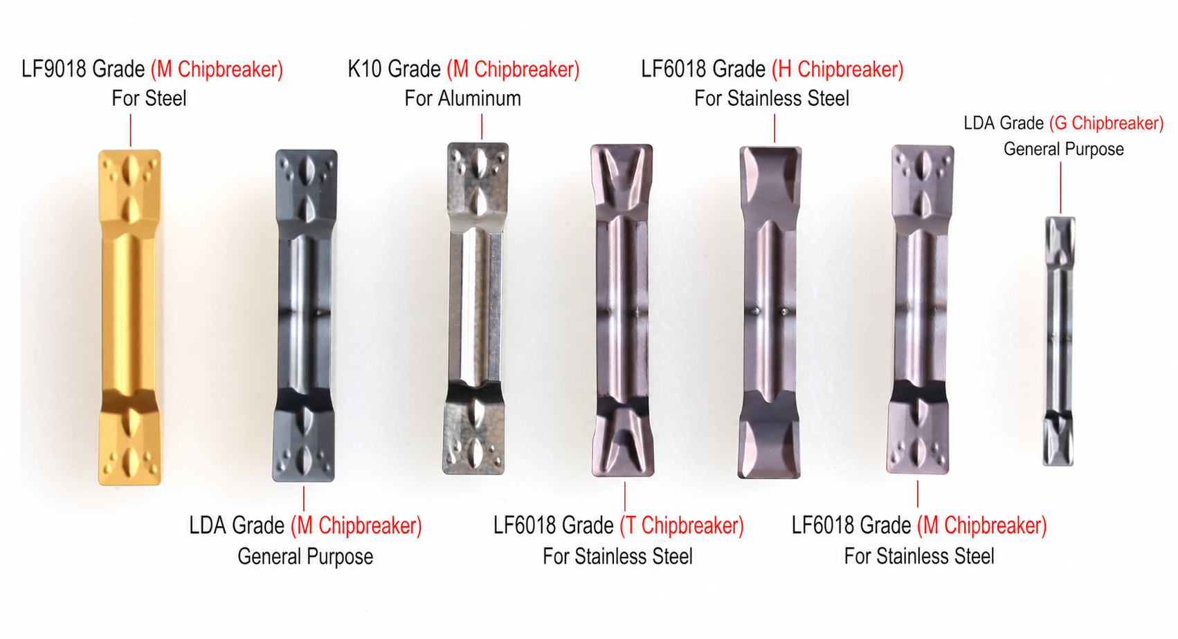
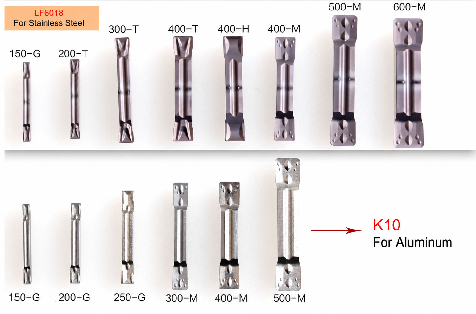
The supplemental comparison images show that insert width, chipbreaker, and grade are separate decisions. They are useful for explaining the range, but they must not be treated as direct KP2500 equivalents.

| Reference Family | Material Focus Shown | Illustrated Width / Geometry | Selection Note |
|---|---|---|---|
| LF9018 | Steel | M-style widths shown from 200 to 500 | A separate grade family; compare coating and chipbreaker before substitution |
| LF6018 | 스테인리스 스틸 | G / T / H / M styles, 150 to 600 shown | Select the chipbreaker according to feed, groove depth, and chip-control demand |
| K10 | Aluminum / non-ferrous | G / M styles, 150 to 500 shown | Sharp, low-adhesion geometry is normally prioritized for aluminum |
| LDA | General-purpose materials | G / M styles, 150 to 500 shown | General-purpose positioning does not remove the need to confirm workpiece and holder compatibility |
◆Technical Specification
| Product Type | Indexable carbide grooving and parting insert |
| 모델 | MGMN300-04-T |
| 등급 | KP2500 |
| Nominal Cutting Width | 3.0 mm class; confirm drawing and tolerance before ordering |
| 코팅 | PVD coating |
| Primary Operations | External grooving / parting off / groove widening where approved |
| Workpiece Materials | Steel and selected stainless steels; conditions dependent |
| Hardness Reference | HRC45–55 applications require validation of rigidity, edge load, and cutting data |
| 호환 홀더 | Holder specifically designated for the complete MGMN300-04-T geometry |
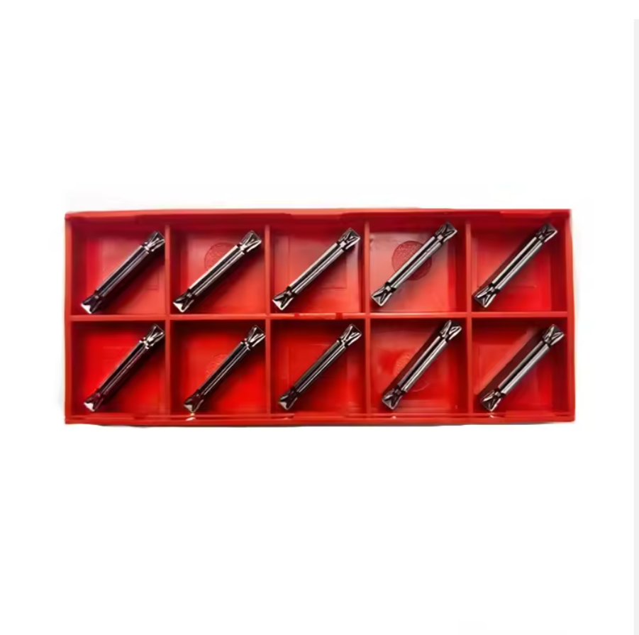
| 패키징 | Original protective box shown; quantity and label should be confirmed by order |
◆Setup and Process Checklist
◆Grooving Troubleshooting
| Observed Problem | Likely Checks | Corrective Direction |
|---|---|---|
| Long or tangled chips | Feed too low, chipbreaker outside its range, poor coolant access | Restore stable chip load and verify chipbreaker, coolant direction, and groove depth |
| 엣지 치핑 | Excess overhang, impact, vibration, unstable workholding, or brittle edge | Improve rigidity, check center height and pocket condition, then review grade and feed |
| Tapered groove walls | Tool misalignment, deflection, damaged seat, or side loading | Realign the holder, reduce projection, inspect the pocket, and verify toolpath strategy |
| 빌드업 에지 | Rubbing, adhesion, low cutting speed, interrupted coolant, or unsuitable grade | Review speed, feed, coating, coolant consistency, and workpiece material group |
| Large parting pip or burr | Center-height error, insert deflection, geometry, or final-feed strategy | Verify center height and alignment, then optimize the final stage of the parting cycle |
Identification, Packaging and Replacement Matching
Keep the original box label until the replacement insert has been validated. The complete product code, grade, lot information, and supplier-specific geometry marking are more reliable than coating color alone.
- ◆Send clear photographs of the insert top, bottom, and side profile.
- ◆Include the holder or blade model and maximum required cutting depth.
- ◆Specify workpiece grade, hardness, bar diameter, groove depth, and coolant method.
- ◆Confirm standard packaging quantity and OEM-label requirements before ordering.
◆Related CNC Turning Solutions
MGR Small-Diameter Internal Tools
Solid-carbide anti-vibration tools for precision boring and internal grooving in small bores.
16IR / 16ER Thread Inserts
Indexable internal and external threading inserts for defined ISO profiles and pitch-specific work.
Turning and Milling Carbide Inserts
Compare CNMG, DNMG, SNMG, TNMG, VNMG, WNMG, and APMT insert families for other CNC operations.
◆Specifications & Size
MGMN300-04-T in KP2500 is a double-ended carbide insert for external grooving and parting. Its nominal cutting-width class is 3.0 mm. Confirm the approved drawing, holder pocket and required groove tolerance before using the width class as a finished-groove specification.
| Item | Product Specification |
|---|---|
| Complete designation | MGMN300-04-T · KP2500 |
| Insert type | Double-ended indexable carbide grooving / parting insert |
| Nominal cutting width | 3.0 mm class; actual width and tolerance subject to drawing confirmation |
| Top geometry | 04-T supplier-specific chip-forming geometry; confirm profile against the supplied part |
| Grade / coating | KP2500 carbide grade / PVD coated; coating composition is not specified |
| Operations | External radial grooving and parting; groove widening only with approved side-cutting strategy |
| Workpiece focus | Steel and selected stainless steels; verify grade and hardness for the actual cut |
| Holder interface | Holder or blade approved for the complete insert geometry and required cutting depth |
| Dimensions still to confirm | Body length, insert height, corner treatment, width tolerance, and holder-dependent maximum depth |
◆Application & Setup
| Operation | Selection and Setup Check |
|---|---|
| External grooving | Match groove width and depth to the drawing and holder; set the edge perpendicular to the workpiece axis. |
| Parting off | Check bar diameter against tool reach; set center height, minimize overhang and maintain chip evacuation. |
| Steel | Confirm steel grade, hardness, continuity of cut, coolant and grade-specific cutting data. |
| 스테인리스 스틸 | Maintain a stable cutting action and effective coolant access; assess chip formation and edge wear in a trial cut. |
Select cutting speed and feed from confirmed KP2500 data for the specific workpiece and setup. No numerical speed, feed or depth range is stated here because these values depend on the holder, material, rigidity and coolant delivery.
◆Holder Matching & Ordering
For a replacement or quotation, send the complete insert and holder codes, clear photos of the insert and box label, workpiece grade and hardness, groove width and depth, bar diameter, coolant method and required quantity.
A matching 3 mm width alone does not guarantee pocket fit or equivalent chip control. See the CNC Insert Selection Guide 또는 request the drawing and holder check.
◆Carbide Insert Customization & OEM
Specify the insert around the machining operation, workpiece and holder. We can review standard replacements, application-specific geometry and private-label requirements using your insert designation, drawing or sample. Available grades, coatings, dimensions and order quantities are confirmed for each requested series.
Geometry & Chip Control
Review chipbreaker, rake, cutting-edge preparation, nose radius and corner design for the operation and workpiece. Confirm holder compatibility before approving a modified geometry.
Substrate & Coating
Select an available carbide grade and coating for the workpiece material, cutting conditions and desired balance of wear resistance and edge toughness.
Dimensions & OEM
Review insert size, thickness, locating and clamping features, tolerances, laser marking and private-label packaging against the approved specification.
◆사용자 지정 옵션
Use the fields below when sending an inquiry. The exact options depend on the insert family and are confirmed in the quotation or approved drawing.
| 사양 | Details to Confirm |
|---|---|
| Insert Type | Turning, milling, threading, grooving or drilling insert; send the designation or drawing. |
| Size & Fit | Shape, size, thickness, inscribed circle or edge length, hole or clamping form, and holder model. |
| 절단 지오메트리 | Chipbreaker, nose or corner radius, edge preparation, cutting direction and application-specific profile. |
| Grade & Coating | Workpiece group and grade, carbide substrate, coating system and wet or dry cutting conditions. |
| Tolerance & Inspection | Critical dimensions, profile requirements, inspection method and any required report. |
| OEM Presentation | Insert or box marking, label content, packaging format and quantity per pack. |
◆How to Request a Custom Insert

Send your insert requirements through our contact form or review our OEM and private-label service.
◆Carbide Insert Quality Control

Insert quality depends on the approved grade, geometry, coating and dimensional specification. We review the requirements at order confirmation and align the inspection scope with the insert series and any customer drawing. Share critical dimensions or documentation needs before production so they can be included in the agreed inspection plan.
01 · Incoming Material
Confirm the specified carbide grade or material documentation against the order requirements.
02 · In-Process Checks
Review dimensions and cutting-edge features during production against the approved specification.
03 · Final Inspection
Check the agreed dimensions, appearance, edge condition, coating identification and marking as applicable.
04 · Packing Review
Verify the item code, quantity, labels and protective packing against the approved order.
◆Inspection & Documentation
Inspection points and acceptance criteria should be agreed for the ordered series. For custom inserts, the approved drawing takes priority over a generic catalogue description.
| Check Area | What to Confirm |
|---|---|
| Dimensions & Fit | Insert size, thickness, corner radius, clamping features and any drawing tolerances. |
| 절단 지오메트리 | Chipbreaker, edge preparation, usable corners and profile where applicable. |
| Grade & Coating | Approved grade and coating designation; any requested verification method. |
| Appearance & Packing | Visible edge damage, marking, item code, count and packing format. |
| Requested Records | Inspection report, material or coating documentation, sample approval or batch identification when agreed. |
◆Order & Delivery
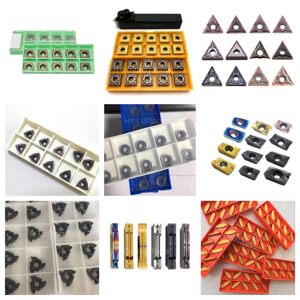

Share a line-by-line list of insert codes and quantities for a mixed-size quotation. Stock status, minimum quantity, sample requirements and production lead time are confirmed for each grade, coating and configuration.
Send your item list and quality requirements through our contact form for specification, availability and delivery confirmation.
◆Product FAQs
What does MGMN300-04-T KP2500 mean?
MGMN identifies the grooving and parting insert family, 300 refers to the nominal 3.0 mm cutting-width class, and KP2500 is the stated PVD-coated carbide grade. The 04-T suffix identifies supplier-specific geometry; confirm its exact profile and corner treatment on the product drawing.
Can the same insert be used for grooving and parting?
It is listed for external grooving and parting. Check the holder's maximum depth, bar diameter, center height, tool projection and coolant access for each operation. Do not assume it is suitable for internal or face grooving.
Will a 3.0 mm insert always produce a 3.0 mm finished groove?
The 3.0 mm designation is nominal. Actual groove width depends on the insert tolerance, corner geometry, alignment, deflection and wear. Request the width tolerance and check the finished groove when a close fit is required.
Is KP2500 suitable for stainless steel or hardened steel?
The listed application covers steel and selected stainless steels with suitable cutting conditions. Hardened workpieces, including HRC45–55, require a separate process trial and grade confirmation; hardness capability is not established by the designation alone.
Can I move the insert sideways to widen a groove?
Only if the insert geometry and holder are approved for the resulting lateral load. Confirm the cutting strategy and leave enough clearance for chip evacuation; a radial grooving designation alone does not establish side-turning capability.
How do I choose speed and feed for this insert?
Provide the workpiece grade and hardness, bar diameter, groove depth, holder model, coolant and machine rigidity. Use confirmed KP2500 cutting data as a starting point, then validate chip control, wear and groove quality in a trial cut.
◆Ordering & OEM FAQs
Will this insert fit my MGMN300 holder?
Check the complete holder and insert codes, pocket length and seat, clamping method, hand and usable depth. Inserts with the same nominal width can differ in body geometry and chipbreaker. Send holder markings and insert photos for a fit check.
Are other widths or chipbreakers available?
Related width classes and geometries can be reviewed by request. Send each complete target code, holder model, workpiece and quantity; availability and compatibility are confirmed per item.
Can I request samples or private-label packaging?
Send the insert code, holder details, trial conditions, expected quantity and packaging or label requirements. Sample availability, MOQ, pack count, artwork and lead time are confirmed in the quotation.
What information should I include with a replacement request?
Provide photos of the original box label and insert from several angles, the holder or blade model, groove width and depth, bar diameter, workpiece grade and hardness, coolant setup, current cutting data, wear problem and requested quantity.
◆Guides & Technical References
For grade, geometry and workpiece checks, see the CNC Insert Selection Guide 그리고 Carbide Insert Types Guide.
For the exact drawing, holder matching or quotation, send us the complete code and application details.
Need Sizes, Pricing or Custom Options?
Send us the required tool type, sizes, quantities, workpiece material and any OEM or custom requirements. We will confirm suitable specifications, availability, lead time and quotation details.
Drawings, size lists and reference photos are welcome.