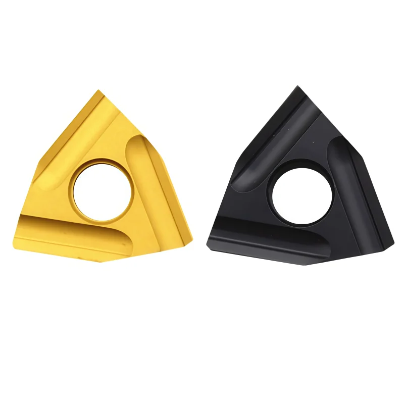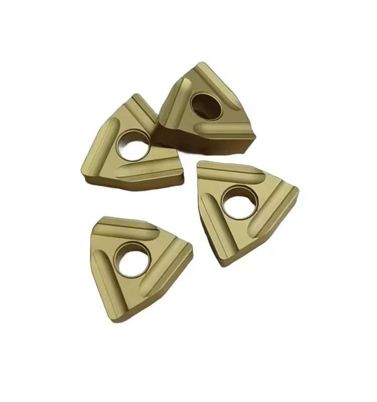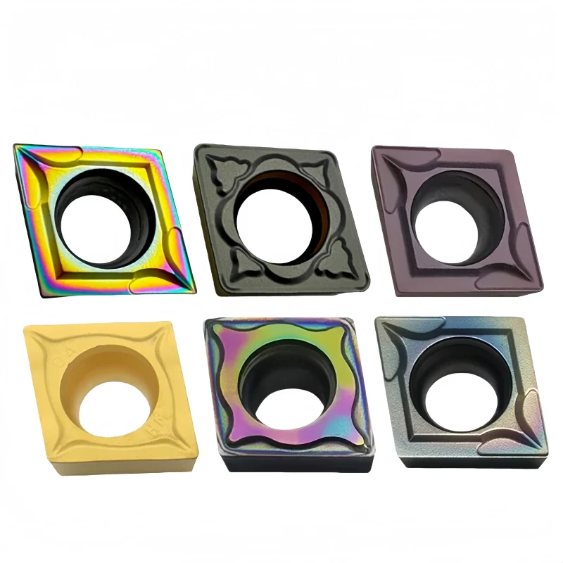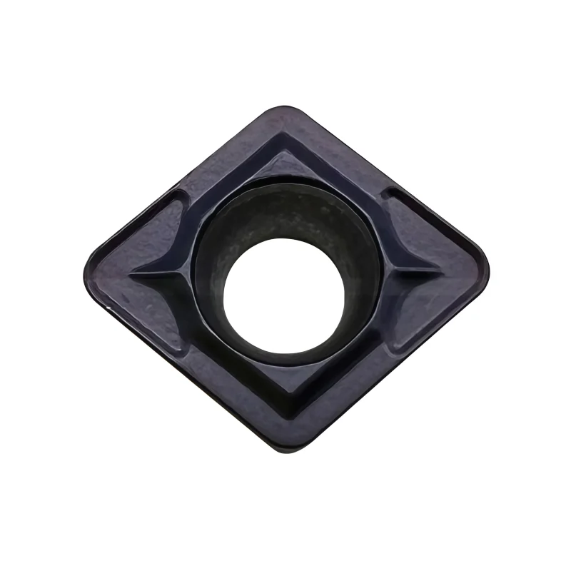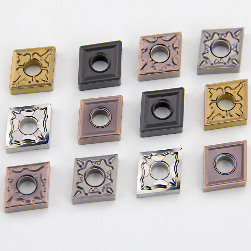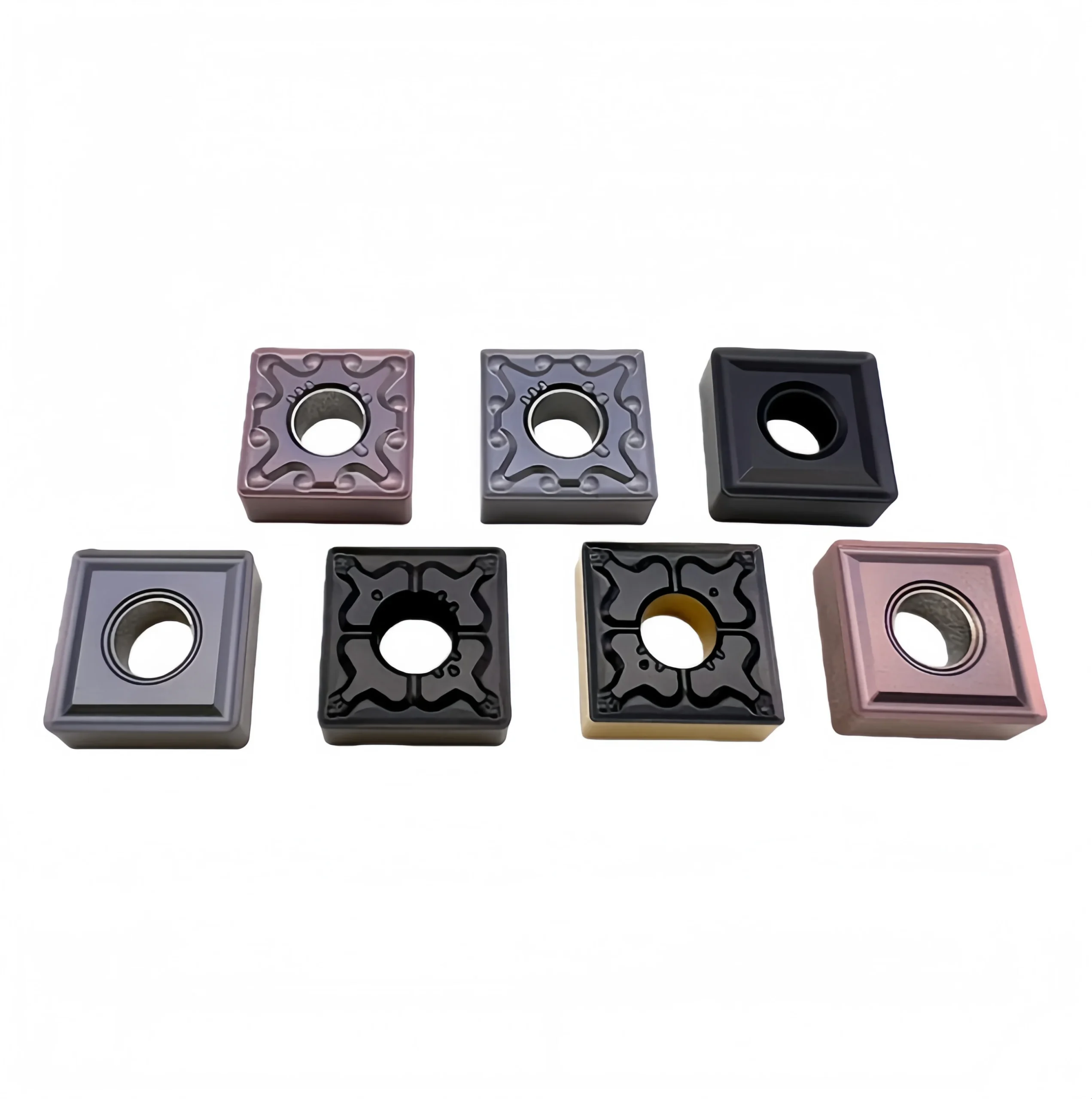
SNMG 120404-MA/120408-TM Carbide Turning Inserts for Steel Turning
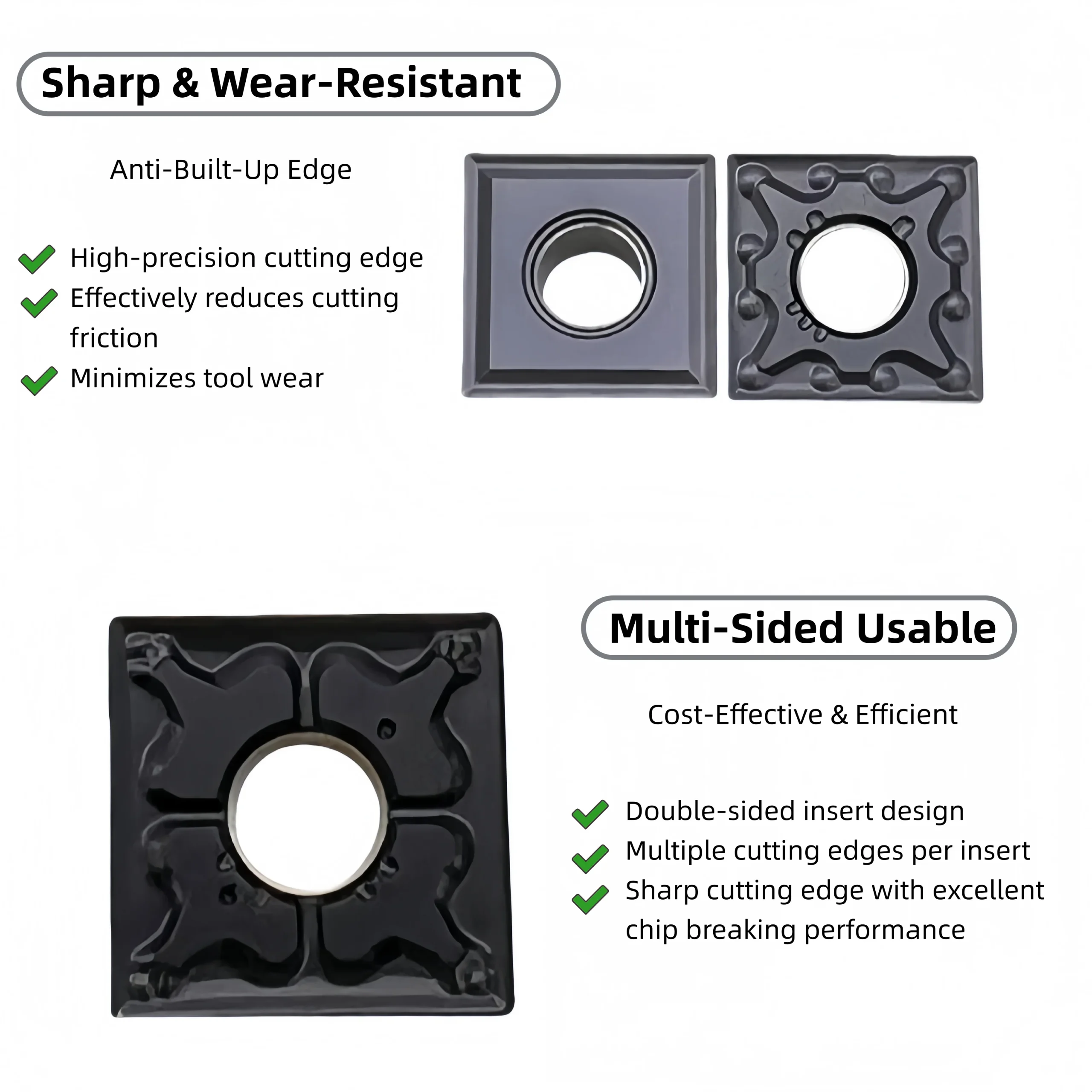
SNMG 120404-MA and 120408-TM carbide turning inserts are designed for stable steel turning, facing and general roughing. The square, double-sided negative geometry provides eight usable cutting edges and strong edge support. Different chipbreakers and coated grades help distributors meet varying requirements for feed rate, depth of cut and production stability.
Qualità costante
Consistent geometry across repeat orders.
Ordini flessibili
Small batches and mixed sizes available.
OEM Support
Custom marking, labels and packaging.
Standard e personalizzati
Standard sizes and custom configurations.
◆Panoramica del prodotto
Il SNMG 120404-MA and SNMG 120408-TM carbide turning inserts are designed for stable external turning, facing and general steel-machining operations. Their square, negative insert geometry provides a strong cutting edge and multiple usable edges, supporting economical CNC turning in continuous and moderately interrupted cutting conditions.
MA and TM chipbreaker options provide different combinations of cutting-edge sharpness, chip-control range and edge strength. Final selection should be based on the workpiece material, cutting depth, feed rate, insert grade, holder rigidity and required surface finish.
| Insert Series | SNMG 1204 | Available Models | 120404-MA / 120408-TM |
|---|---|---|---|
| Insert Shape | Square, 90° included angle | Clearance | Negative, 0° clearance |
| Corner Radius | 0.4 mm / 0.8 mm | Operations | External turning / Facing |
| Materiale del pezzo da lavorare | Steel; other materials grade dependent | Opzioni di rivestimento | PVD / CVD options |
| Standard Pack | 10 pieces per box | Supply Options | Standard / Mixed models / Private label |
Chipbreaker definitions and material suitability may vary by grade series. Confirm the complete insert code before ordering.
◆MA and TM Chipbreaker Selection
| Modello | Corner Radius | General Positioning | Selection Considerations |
|---|---|---|---|
| SNMG 120404-MA | 0.4 mm | Sharper-radius option | Consider for lighter cuts and operations requiring lower radial cutting force. |
| SNMG 120408-TM | 0.8 mm | Stronger-radius option | Consider where stronger edge support and stable medium turning are required. |
This table provides general positioning only. Confirm the chipbreaker and grade according to the manufacturer’s complete code and actual cutting conditions.
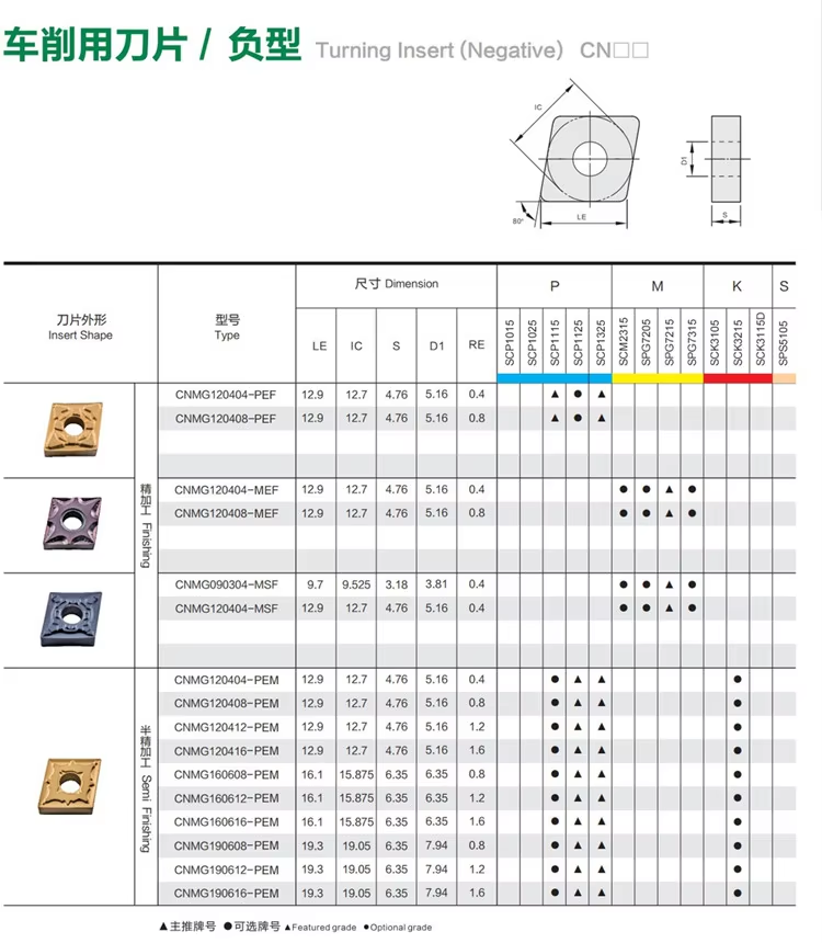
Use the following parameter images to compare available SNMG 1204 models, chipbreakers, grades and workpiece-material recommendations. Send the complete existing code when requesting replacement matching.
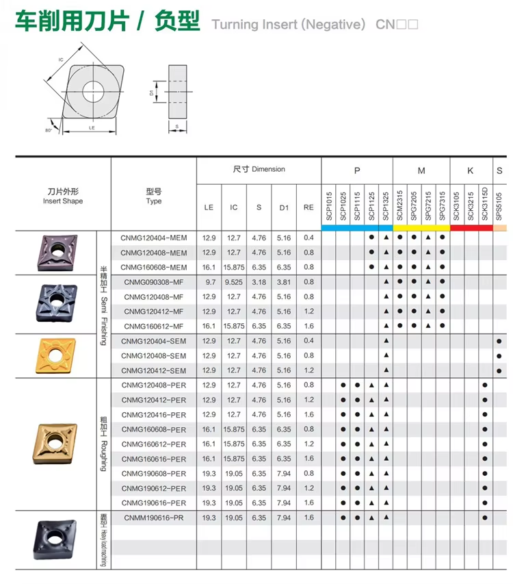
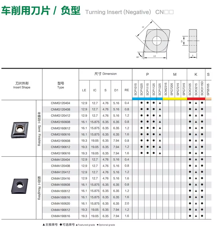
◆Product and Chipbreaker Details
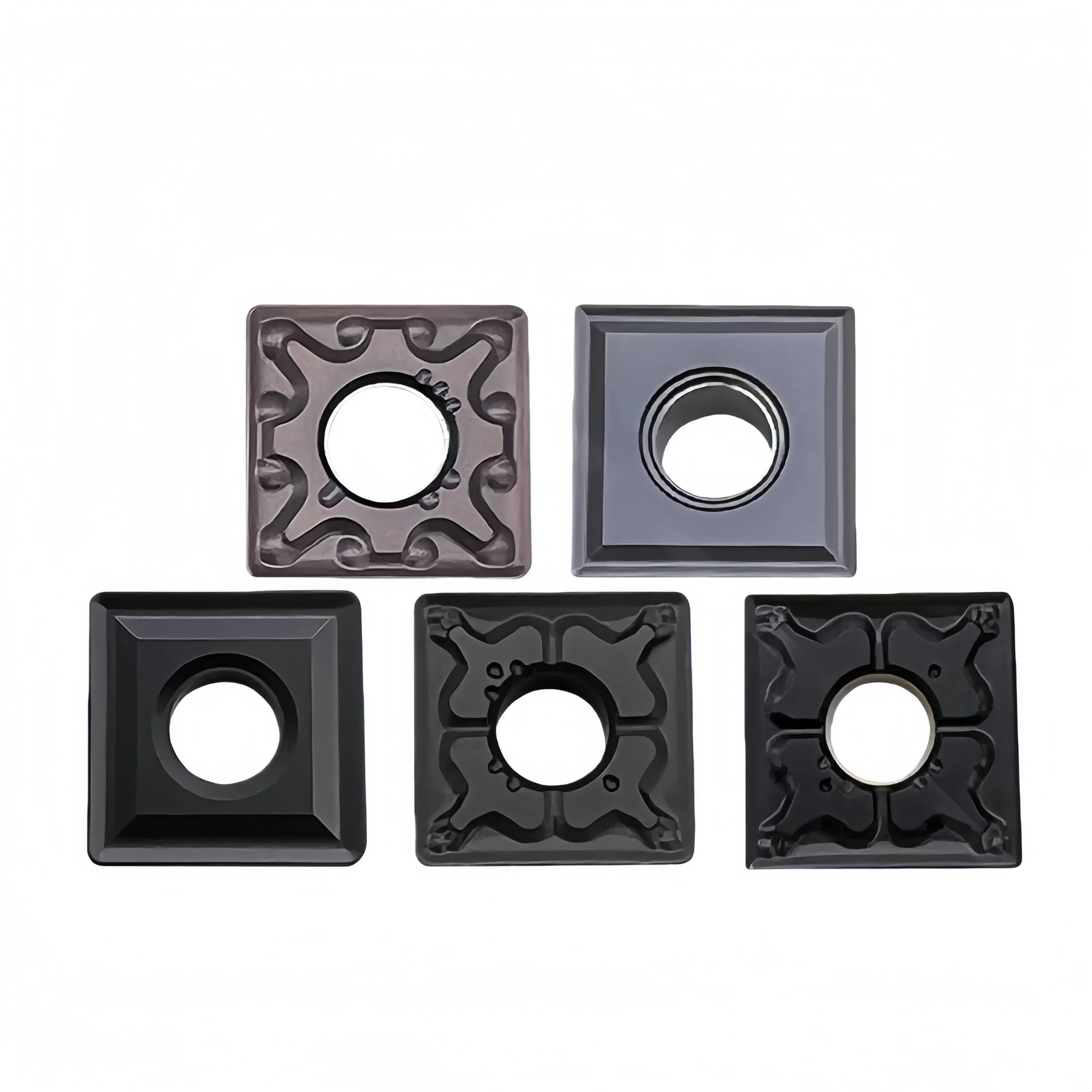
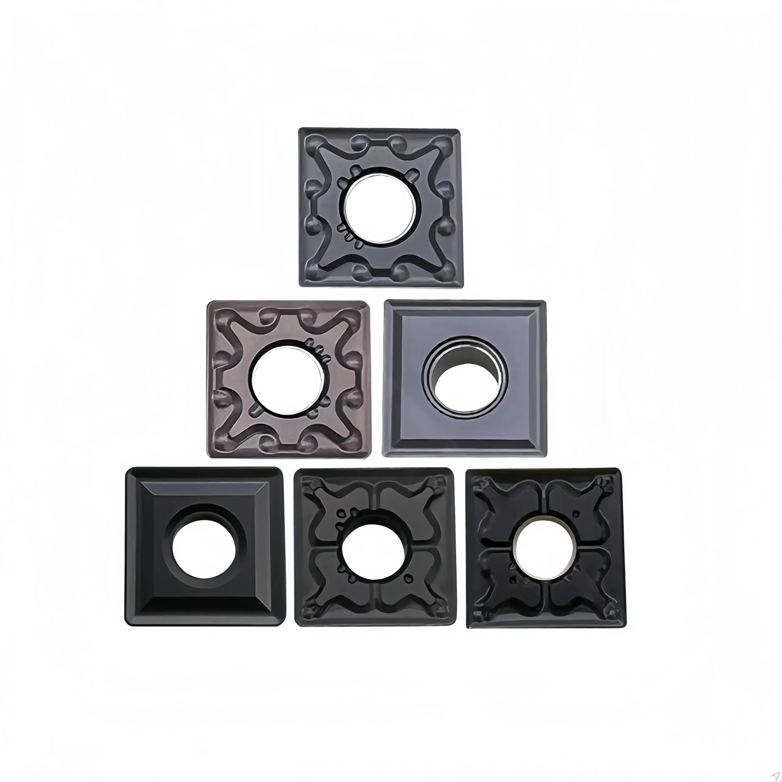
SNMG inserts may be supplied with different carbide substrates and PVD or CVD coatings. The appropriate grade depends on the steel type, hardness, cutting speed, coolant condition and whether the cut is continuous or interrupted.
Insert appearance and coating color alone are not sufficient for grade identification. Use the complete code marked on the insert or original package.
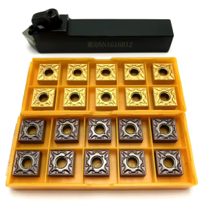
Inserts are packed in compartment boxes to protect the cutting edges and keep model and batch information clear during storage, order picking and transportation.
- Complete insert code, grade and chipbreaker
- Compatible tool-holder model
- Workpiece material and hardness
- Turning operation, cutting depth and feed
- Required quantity and packaging option
If the full code is unavailable, send clear photographs of the insert marking, chipbreaker surface, side profile and compatible holder.
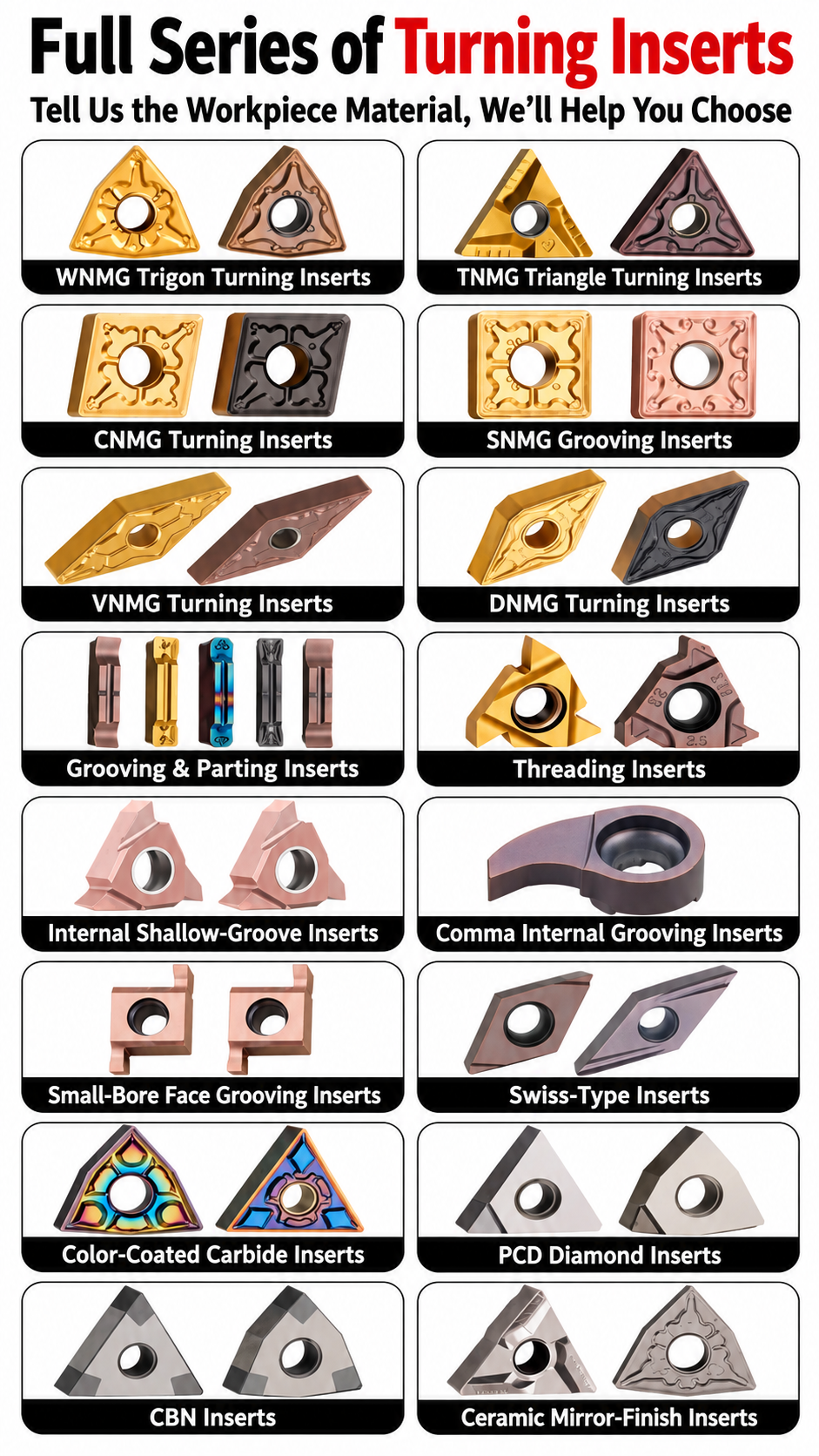
◆Specifications & Size Chart
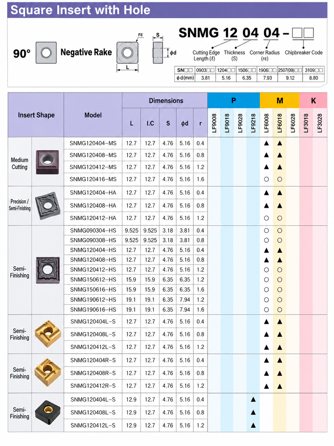
The supplied SNMG chart identifies a 90° square, negative insert with a fixing hole. The table below transcribes its SNMG 1204 dimension rows. For most listed rows, L and IC are 12.7 mm, S is 4.76 mm and the fixing-hole diameter is 5.16 mm. The final L-S group is separately printed with L = 12.9 mm. Match the complete suffix and grade rather than the corner radius alone.
| Chart Category | Charted Model | L (mm) | IC (mm) | S (mm) | φd (mm) | r (mm) | Marked Grade Columns |
|---|---|---|---|---|---|---|---|
| Medium cutting | SNMG120404-MS | 12.7 | 12.7 | 4.76 | 5.16 | 0.4 | LF6008 / LF6018 |
| Medium cutting | SNMG120408-MS | 12.7 | 12.7 | 4.76 | 5.16 | 0.8 | LF6008 / LF6018 |
| Medium cutting | SNMG120412-MS | 12.7 | 12.7 | 4.76 | 5.16 | 1.2 | LF6008 / LF6018 |
| Medium cutting | SNMG120416-MS | 12.7 | 12.7 | 4.76 | 5.16 | 1.6 | LF6008 / LF6018 |
| Precision / semi-finishing | SNMG120404-HA | 12.7 | 12.7 | 4.76 | 5.16 | 0.4 | LF6008 / LF6018 |
| Precision / semi-finishing | SNMG120408-HA | 12.7 | 12.7 | 4.76 | 5.16 | 0.8 | LF6008 / LF6018 |
| Precision / semi-finishing | SNMG120412-HA | 12.7 | 12.7 | 4.76 | 5.16 | 1.2 | LF6008 / LF6018 |
| Semi-finishing | SNMG120404-HS | 12.7 | 12.7 | 4.76 | 5.16 | 0.4 | LF6008 / LF6018 |
| Semi-finishing | SNMG120408-HS | 12.7 | 12.7 | 4.76 | 5.16 | 0.8 | LF6008 / LF6018 |
| Semi-finishing | SNMG120412-HS | 12.7 | 12.7 | 4.76 | 5.16 | 1.2 | LF6008 / LF6018 |
| Semi-finishing | SNMG120404L-S | 12.7 | 12.7 | 4.76 | 5.16 | 0.4 | LF6008 / LF6018 |
| Semi-finishing | SNMG120408L-S | 12.7 | 12.7 | 4.76 | 5.16 | 0.8 | LF6008 / LF6018 |
| Semi-finishing | SNMG120412L-S | 12.7 | 12.7 | 4.76 | 5.16 | 1.2 | LF6008 / LF6018 |
| Semi-finishing | SNMG120404R-S | 12.7 | 12.7 | 4.76 | 5.16 | 0.4 | LF6008 / LF6018 |
| Semi-finishing | SNMG120408R-S | 12.7 | 12.7 | 4.76 | 5.16 | 0.8 | LF6008 / LF6018 |
| Semi-finishing | SNMG120412R-S | 12.7 | 12.7 | 4.76 | 5.16 | 1.2 | LF6008 / LF6018 |
| Semi-finishing | SNMG120404L-S | 12.9 | 12.7 | 4.76 | 5.16 | 0.4 | LF9218 |
| Semi-finishing | SNMG120408L-S | 12.9 | 12.7 | 4.76 | 5.16 | 0.8 | LF9218 |
| Semi-finishing | SNMG120412L-S | 12.9 | 12.7 | 4.76 | 5.16 | 1.2 | LF9218 |
◆Specification Checklist by Model
| Parametro | Details to Confirm |
|---|---|
| Title models | The Overview names SNMG 120404-MA and SNMG 120408-TM, but neither suffix appears in the supplied chart. Request their own drawings and order codes before publishing their dimensions as verified. |
| Shape and size | 90° square, negative insert with a fixing hole. The charted SNMG 1204 rows list IC 12.7 mm, S 4.76 mm and φd 5.16 mm; check L by exact row. |
| Raggio d'angolo | Charted 120404, 120408, 120412 and 120416 variants correspond to r 0.4, 0.8, 1.2 and 1.6 mm where those rows are listed. |
| Chipbreaker | MS, HA, HS, L-S and R-S are the charted suffixes. Do not treat MA or TM as synonyms for any of them. |
| Grade and workpiece | The chart marks LF6008 / LF6018 for many 1204 rows and LF9218 for the second L-S group, under its M columns. Its P columns are unmarked; confirm a grade approved for the intended steel. |
| Holder and order | Confirm square 1204 holder pocket, seat, clamp, grade, coating, pack quantity and stock using the complete manufacturer code. |
◆How to Select the Insert
For further selection checks, see the CNC Insert Selection Guide.
◆Starting Cutting Data
This chart provides insert dimensions and grade-column marks, but no verified cutting speed, feed or depth-of-cut values for the Overview’s MA/TM models. Its P-grade columns do not identify an approved steel-turning grade. Obtain cutting data for the exact insert geometry and carbide grade before setting production parameters.
◆Related Series & Technical References
Compare insert shapes in the carbide turning and milling insert range. For an MA/TM drawing, compatible holder or steel-turning grade, send the complete model and application details.
◆Carbide Insert Customization & OEM
Specify the insert around the machining operation, workpiece and holder. We can review standard replacements, application-specific geometry and private-label requirements using your insert designation, drawing or sample. Available grades, coatings, dimensions and order quantities are confirmed for each requested series.
Geometry & Chip Control
Review chipbreaker, rake, cutting-edge preparation, nose radius and corner design for the operation and workpiece. Confirm holder compatibility before approving a modified geometry.
Substrate & Coating
Select an available carbide grade and coating for the workpiece material, cutting conditions and desired balance of wear resistance and edge toughness.
Dimensions & OEM
Review insert size, thickness, locating and clamping features, tolerances, laser marking and private-label packaging against the approved specification.
◆Opzioni di personalizzazione
Use the fields below when sending an inquiry. The exact options depend on the insert family and are confirmed in the quotation or approved drawing.
| Specifiche | Details to Confirm |
|---|---|
| Insert Type | Turning, milling, threading, grooving or drilling insert; send the designation or drawing. |
| Size & Fit | Shape, size, thickness, inscribed circle or edge length, hole or clamping form, and holder model. |
| Geometria di taglio | Chipbreaker, nose or corner radius, edge preparation, cutting direction and application-specific profile. |
| Grade & Coating | Workpiece group and grade, carbide substrate, coating system and wet or dry cutting conditions. |
| Tolerance & Inspection | Critical dimensions, profile requirements, inspection method and any required report. |
| OEM Presentation | Insert or box marking, label content, packaging format and quantity per pack. |
◆How to Request a Custom Insert

Send your insert requirements through our contact form or review our OEM and private-label service.
◆Carbide Insert Quality Control

Insert quality depends on the approved grade, geometry, coating and dimensional specification. We review the requirements at order confirmation and align the inspection scope with the insert series and any customer drawing. Share critical dimensions or documentation needs before production so they can be included in the agreed inspection plan.
01 · Incoming Material
Confirm the specified carbide grade or material documentation against the order requirements.
02 · In-Process Checks
Review dimensions and cutting-edge features during production against the approved specification.
03 · Final Inspection
Check the agreed dimensions, appearance, edge condition, coating identification and marking as applicable.
04 · Packing Review
Verify the item code, quantity, labels and protective packing against the approved order.
◆Inspection & Documentation
Inspection points and acceptance criteria should be agreed for the ordered series. For custom inserts, the approved drawing takes priority over a generic catalogue description.
| Check Area | What to Confirm |
|---|---|
| Dimensions & Fit | Insert size, thickness, corner radius, clamping features and any drawing tolerances. |
| Geometria di taglio | Chipbreaker, edge preparation, usable corners and profile where applicable. |
| Grade & Coating | Approved grade and coating designation; any requested verification method. |
| Appearance & Packing | Visible edge damage, marking, item code, count and packing format. |
| Requested Records | Inspection report, material or coating documentation, sample approval or batch identification when agreed. |
◆Order & Delivery
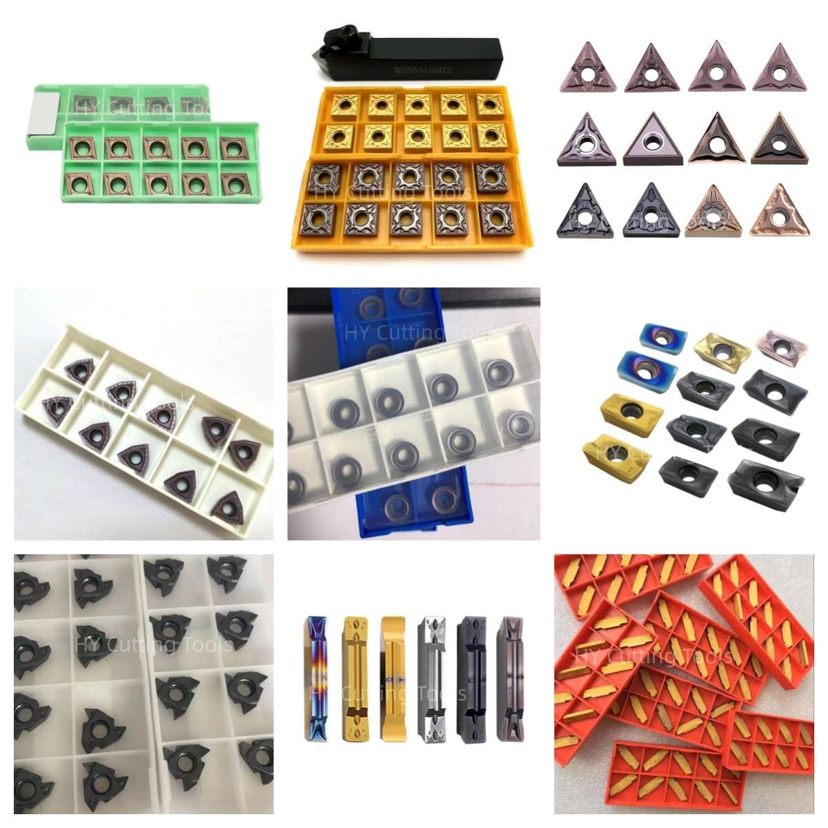

Share a line-by-line list of insert codes and quantities for a mixed-size quotation. Stock status, minimum quantity, sample requirements and production lead time are confirmed for each grade, coating and configuration.
Send your item list and quality requirements through our contact form for specification, availability and delivery confirmation.
◆Product FAQs
What is an SNMG turning insert?
SNMG denotes a square, negative-clearance carbide insert with a fixing hole and a specified tolerance class. It is used in a compatible turning holder for operations such as external turning and facing. Check the complete insert code and holder pocket before ordering.
What is the difference between SNMG 120404 and 120408?
In these designations, the final two digits identify nominal corner radii of 0.4 mm and 0.8 mm. Radius selection affects edge support, cutting force and the finish obtainable at a given feed. Compare the full model, chipbreaker and carbide grade as well as the radius.
Does the size chart list SNMG 120404-MA and SNMG 120408-TM?
No. The supplied SNMG chart lists MS, HA, HS, L-S and R-S variants, but does not show MA or TM dimensional rows. The charted dimensions are references for the models actually listed; request the MA and TM drawings before treating either configuration as dimensionally verified.
Are MA and TM the same as the chipbreakers in the chart?
No equivalence is established by the supplied chart. Chipbreaker suffixes depend on the manufacturer's series and identify a particular cutting geometry. Confirm the MA or TM drawing, recommended feed and depth-of-cut range, and available grade for each complete code.
Are these inserts suitable for steel turning?
The product Overview positions them for steel turning, but the supplied size chart does not mark a grade in its P (steel) columns for the listed rows. State the steel grade, hardness, operation and cutting conditions so a P-group grade and the MA or TM configuration can be confirmed before production use.
Can I use an SNMG insert in a CNMG holder?
No. SNMG is square with a 90° included angle; CNMG is an 80° diamond. Their holder pockets and seating geometry differ. Match the full insert code to a holder specified for that shape, size, thickness, fixing hole and clamping system.
◆Ordering & OEM FAQs
What information is needed to confirm an MA or TM insert?
Send the complete original insert code, grade and chipbreaker, photographs of both sides or the box label, the holder model, steel grade, operation, current cutting conditions and required quantity. Request the matching series drawing and grade-specific cutting data.
Can I order different radii or models together?
Send a line-by-line list showing each complete code, grade, radius and quantity. Mixed-model availability, minimum quantity and dispatch time are confirmed for each configuration. The Overview's 10-piece box quantity is a reference to confirm at quotation.
Can I request samples before a production order?
Provide the complete code and holder, material, cutting conditions and evaluation criteria. Confirm sample availability by grade and geometry, then compare chip control, wear, finish and cost per accepted part under consistent machining conditions.
Are custom grades, marking or private-label packaging available?
The Overview lists coating and private-label options. Send the required substrate or grade, coating, marking, label artwork, packing quantity and target application for a feasibility review. The approved drawing and quotation define the final specification and lead time.
◆Guides & Technical References
Use the CNC Insert Selection Guide to review shape, holder fit, grade, corner radius and chipbreaker selection. The Carbide Insert Types Guide explains the wider insert families.
For the exact MA or TM drawing, approved steel-turning grade and quotation, send the complete insert and holder codes with your workpiece and quantity.
Need Sizes, Pricing or Custom Options?
Send us the required tool type, sizes, quantities, workpiece material and any OEM or custom requirements. We will confirm suitable specifications, availability, lead time and quotation details.
Drawings, size lists and reference photos are welcome.