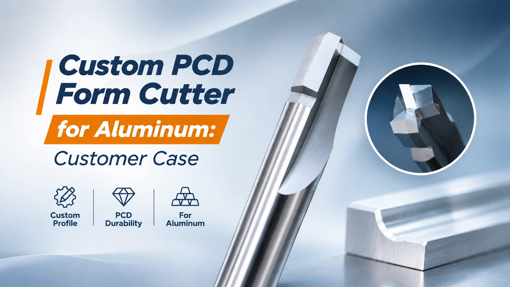
Custom Form Chamfer Cutter for Copper: An 80° Design Case
DRAWING-BASED TOOL DESIGN / COPPER MACHINING
Diese custom form chamfer cutter was specified for hole-mouth finishing in TU1 oxygen-free copper heat-sink components. The customer needed an 80° included profile, small R0.05 radii and repeatable chamfered openings across six holes per component.
The proposed solution is an uncoated solid carbide cutter with polished cutting surfaces. This case explains the drawing requirements, the reasons for that surface choice and the checks needed before the cutter is accepted for production.
In this case
The machining requirement
The customer’s brief called for a formed chamfer around the hole openings without a separate deburring operation. The required result was a consistent edge profile, rather than a chamfer judged only by appearance.
Die 80° included angle is one reason a standard 90° cutter cannot be selected by shank diameter alone. With a symmetric conical profile, 80° corresponds to 40° per side relative to the tool axis. The angle definition must remain clear when a drawing is transferred between purchasing, engineering and the tool manufacturer.
The small radii and neighboring profile features also matter. A cutter with the correct nominal angle but different transitions can leave a different form at the hole opening. The full profile therefore needs to be reviewed as a drawing-based requirement.
For this type of geometry, our custom form cutter service provides the appropriate starting point for a technical review.
Custom form chamfer cutter geometry
The supplied tool drawing defines the cutter profile and its reference dimensions. The table summarizes the main requirements; it does not replace the complete drawing used for manufacture.
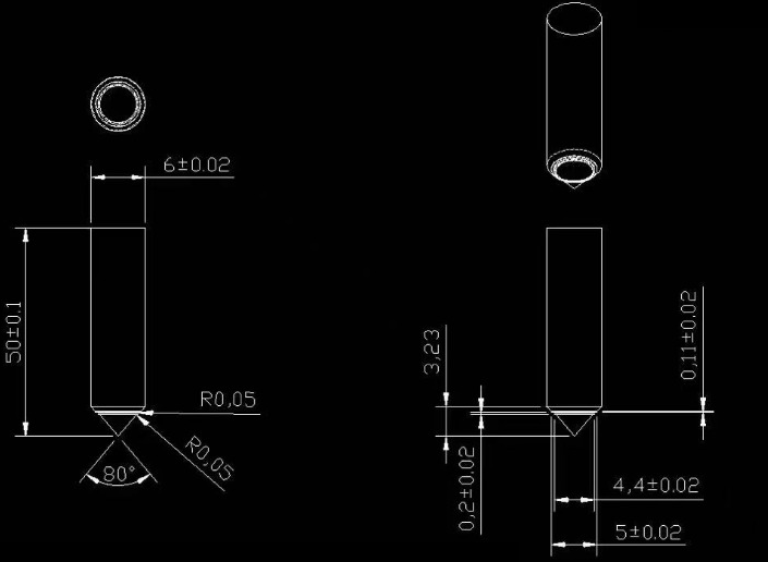
R0.05 specifies the profile radii shown on the drawing. Cutting-edge preparation is controlled separately.
Why the proposal uses uncoated, polished carbide
Uncoated, polished carbide is the proposal for this case. It is not a universal rule for every copper alloy or cutting operation. Any change in coating, edge preparation or carbide grade should be assessed together with the workpiece material and cutting conditions.
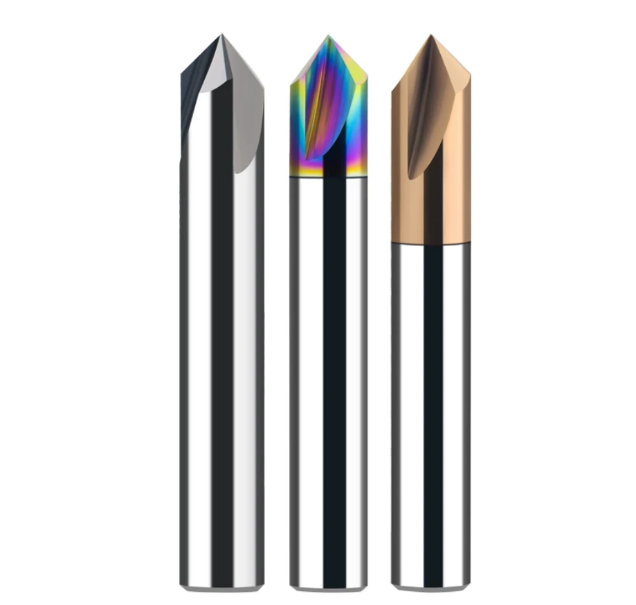
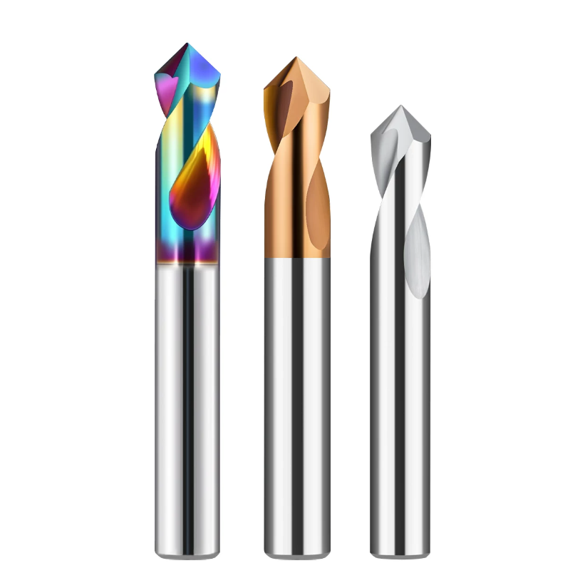
Standard Chamfer Mills & Multi-Function Spot Drill and Chamfer Mills
Standard chamfer mills are primarily used for edge chamfering and deburring, while multi-function spot drill and chamfer mills also provide hole-spotting capability through their specialized tip geometry.
Production targets and acceptance
The technical brief sets a tool-life target exceeding 3,000 components. At six holes per component, the 3,000-part checkpoint corresponds to 18,000 hole positions for chamfering. This is a specified acceptance target, not a reported machining result.
Part quality remains the functional requirement. A cutter can reach the hole-count target and still fail acceptance if the edge profile has drifted or burrs have appeared. Likewise, a wear measurement alone does not prove that the chamfer remains within tolerance.
The agreed trial should record the actual spindle speed, feed, coolant delivery, toolholding and workpiece condition. These settings are not supplied here, so this case does not prescribe cutting data or promise the same output on another machine.
How to inspect and trial the cutter
If results drift, inspect the holder, runout, chip removal and coolant delivery as well as the cutter. Our Leitfaden zur Fehlerbehebung bei der Zerspanung explains how to separate setup and process problems from a tool-selection issue.
Questions about a similar custom cutter
Can a standard 90° chamfer mill replace this tool?
The standard tool would need to match the required finished profile. This brief specifies an 80° included angle, R0.05 radii and additional form details, so matching the shank diameter is insufficient. For conventional profiles, compare the listed angles and dimensions in our standard solid carbide chamfer mill range.
Does R0.05 describe the rounding of the cutting edge?
Here, R0.05 refers to the radii called out on the tool profile. Cutting-edge preparation is a separate manufacturing detail. Both need to be controlled so finishing the edge does not change the required form.
Can the same profile be reviewed for brass or aluminum?
Yes. Send the exact material grade, operation and cutting conditions so the cutting geometry and surface finish can be assessed for that application. A matching profile alone does not establish that the same tool specification is suitable.
What should I send for a similar custom cutter?
Send the tool or part drawing, workpiece material, required profile and quantity. If some details are open, identify them so we can review a tool proposal. Include the machine, holder and current cutting conditions when available.
Discuss your custom form chamfer cutter
HY Cutting Tools can review special angles, radii, profiles, lengths and surface-finish requirements from your drawing or sample. Start with the drawing, material and quantity; sample and inspection requirements can be agreed during technical review. For other tool types, explore our custom cutting tools service.