MDR Series Solid Carbide Micro Thread Relief Grooving Bars for Small Bore Machining
Consistent Quality
Consistent geometry across repeat orders.
Flexible Bestellungen
Small batches and mixed sizes available.
OEM Support
Custom marking, labels and packaging.
Standard und Sonderanfertigungen
Standard sizes and custom configurations.
MDR Micro Thread Relief Grooving Bars
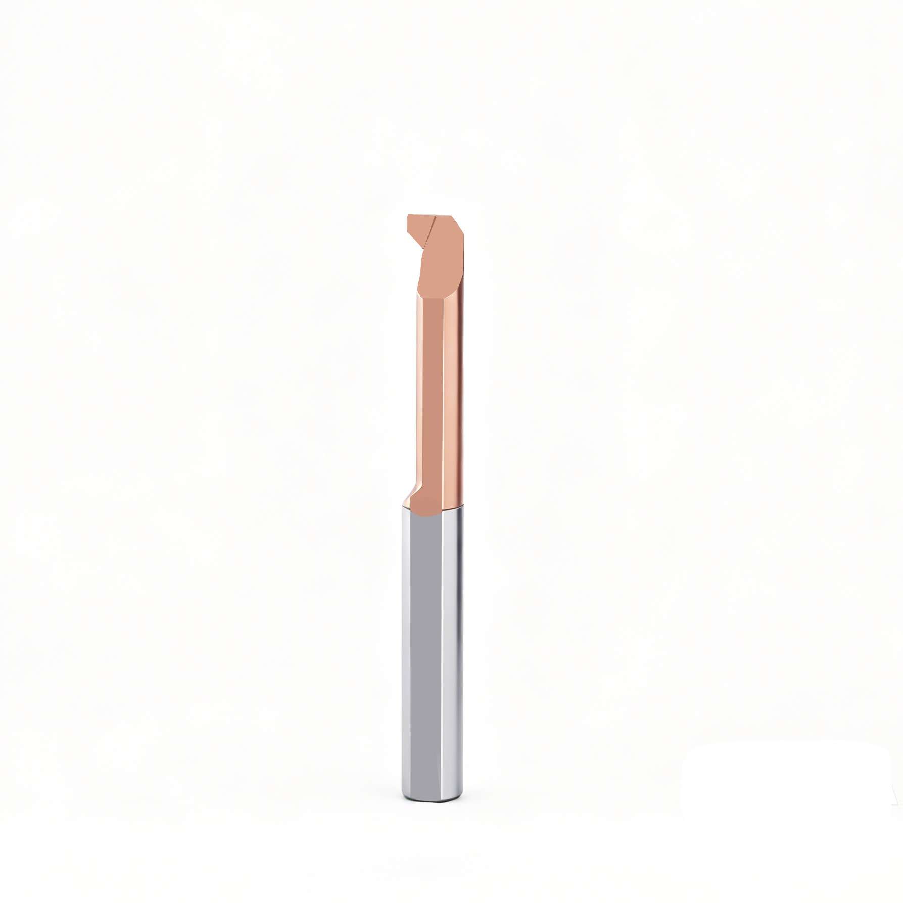
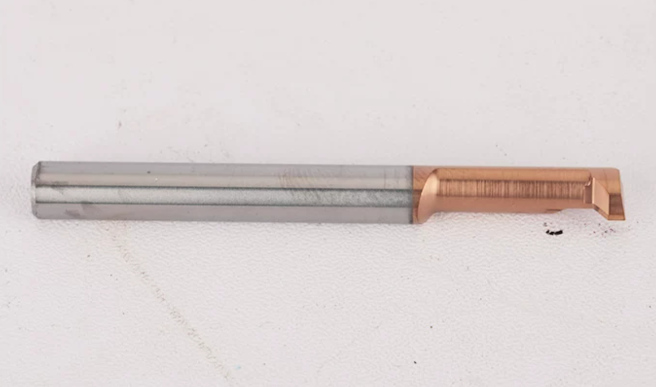
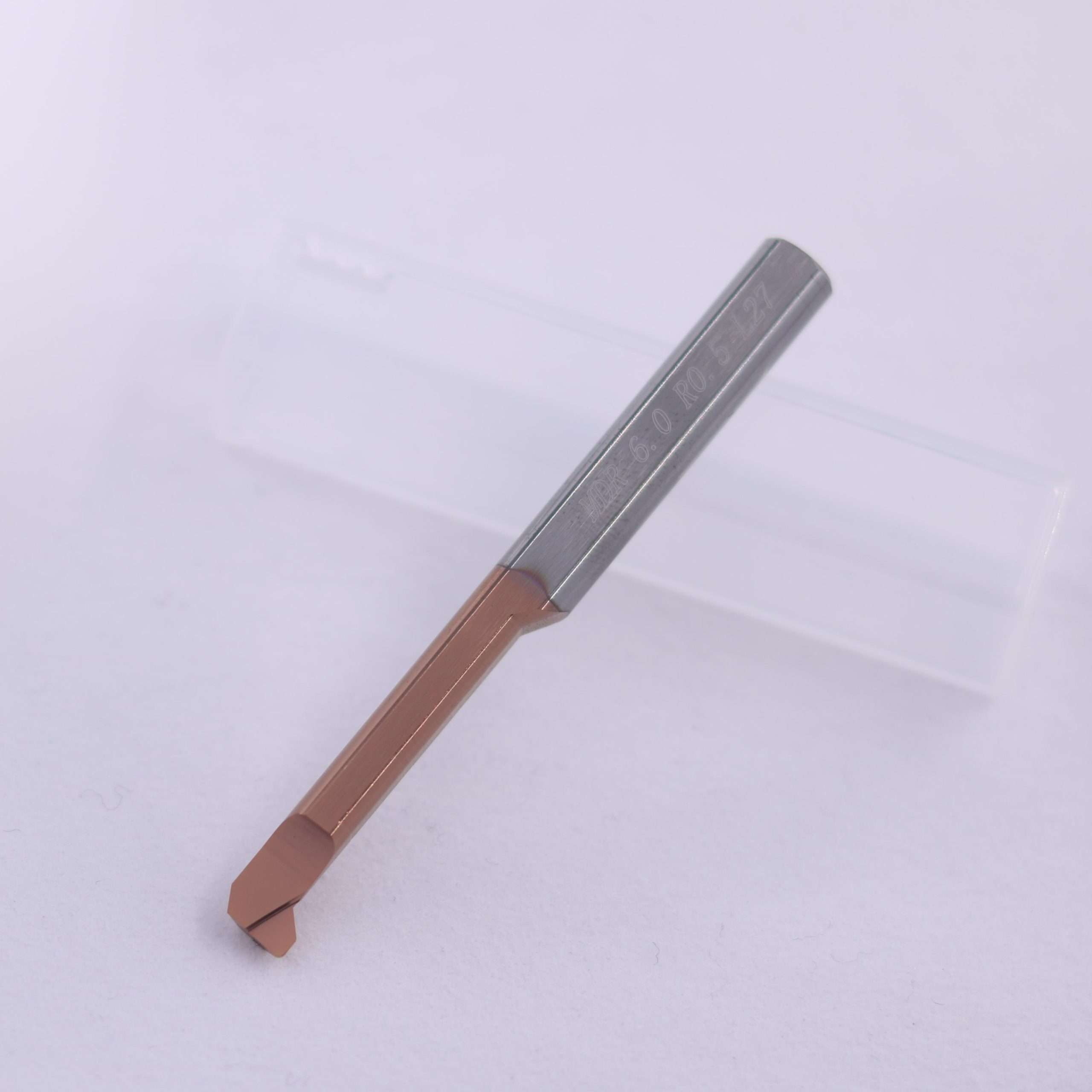
MDR series solid carbide micro grooving bars are designed for machining thread-relief grooves, thread runout areas and internal undercuts in small bores. The precision-ground cutting geometry combines a narrow 1.5 mm cutting section, R0.5 corner radius and compact neck design for controlled access near internal threads and shoulders.
Available in right-hand MDR and left-hand MDL configurations, the series covers minimum bore diameters from 4.1 mm to 6.1 mm. Standard, stainless-steel and drawing-based customized versions are available for precision components, sleeves, bushings and Swiss-type CNC turned parts.
Produktübersicht
Key Product Advantages
Precision-ground profile for producing controlled relief and runout grooves next to internal threads.
Standard models support minimum machining diameters of Ø4.1, Ø5.1 and Ø6.1 mm.
Integral carbide construction provides rigidity and helps control deflection during precision small-bore machining.
MDR right-hand and MDL left-hand tools support different spindle directions, holder positions and machining paths.
Typische Anwendungen
| Anmeldung | Machining Purpose |
|---|---|
| Internal Thread Relief | Produces a controlled runout area at the end of an internal thread. |
| Internal Undercutting | Machines narrow relief features behind internal shoulders and stepped bores. |
| Shoulder Relief | Creates tool clearance and seating relief near an internal shoulder. |
| Chamfering & Profiling | Supports light internal chamfering and profile finishing when permitted by the tool path and component geometry. |

Product Detail Photo

Tool Geometry & Structure
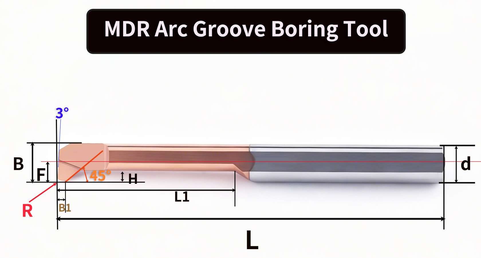
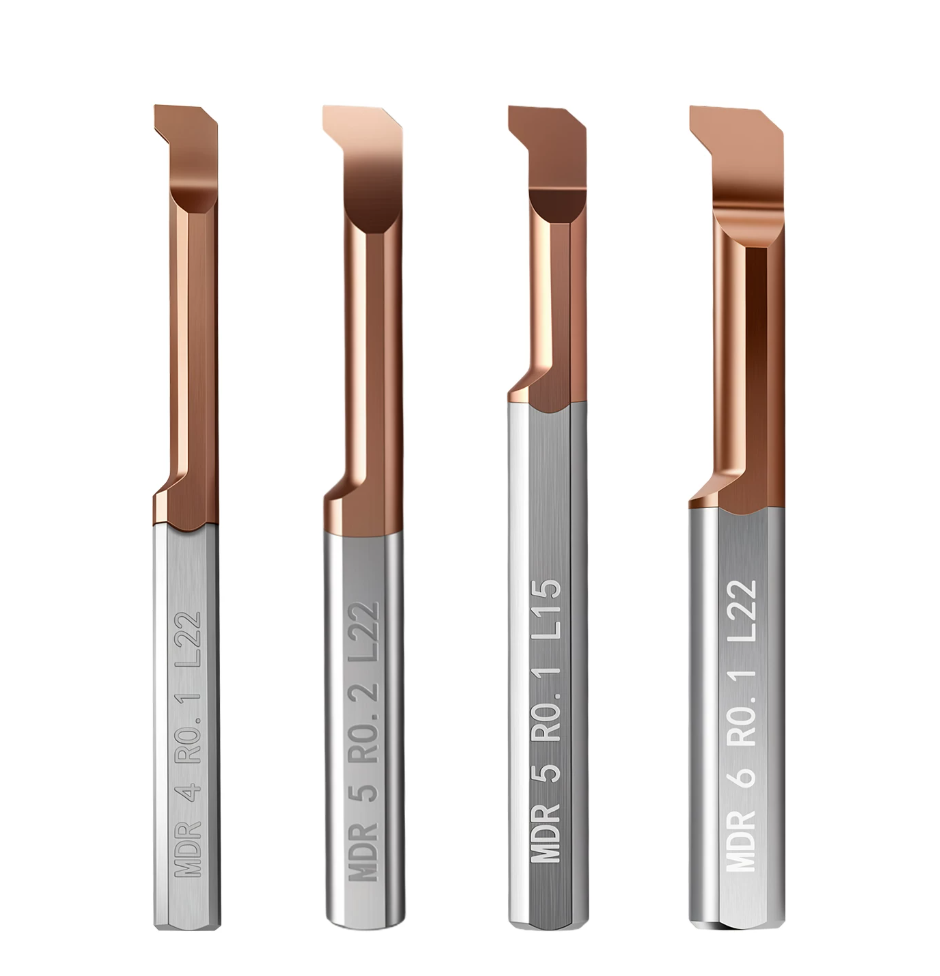
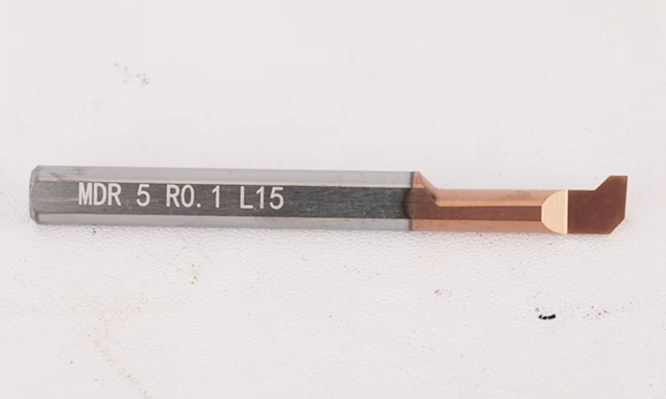
The MDR cutting profile combines a 45° front transition, 3° clearance geometry, R0.5 corner radius and a 1.5 mm cutting section. This geometry provides clearance for machining narrow relief features inside restricted bores.
For best stability, select the shortest working length that can reach the groove and verify the complete approach, cutting and retraction path before machining.
Tool Nomenclature & Selection Guide
Select the MDR or MDL micro thread-relief grooving bar according to cutting direction, minimum bore diameter, working length, corner radius, workpiece material and required internal clearance.
| Code | Beschreibung | Example |
|---|---|---|
| MDR / MDL | Cutting Direction | MDR = Right Hand / MDL = Left Hand |
| 4 / 5 / 6 | Minimum Bore Size Group | Minimum bore Ø4.1 / Ø5.1 / Ø6.1 mm |
| R0.5 | Corner Radius | 0.5 mm radius |
| L18 / L24 / L27 | Working Length L1 | 18 / 24 / 27 mm |
| SSS | Stainless Steel Version | MDR 4 R0.5 L18 SSS |
Dimensions & Available Sizes
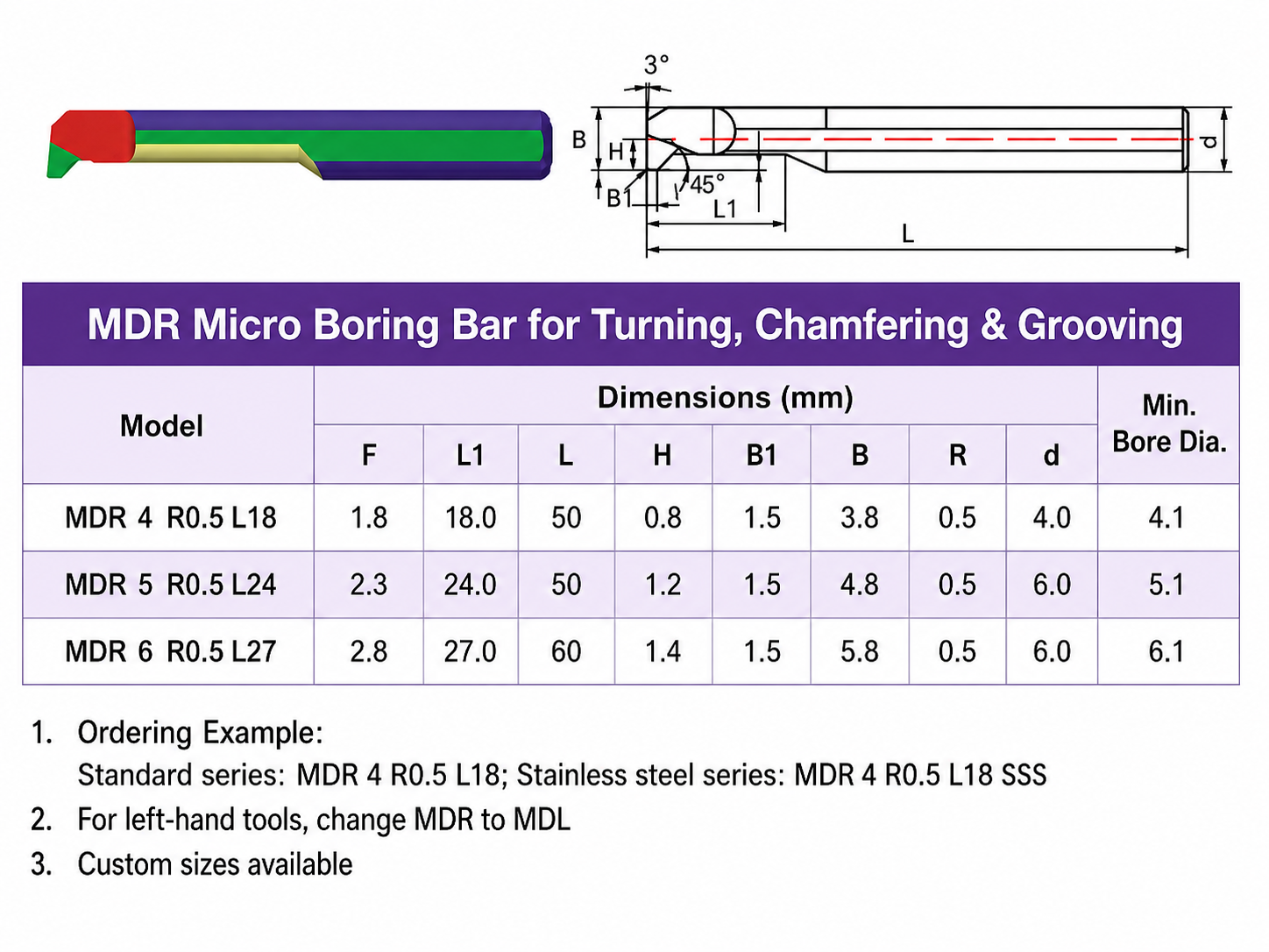
Dimensions are shown in millimetres. Custom sizes, left-hand tools and application-specific geometries are available according to drawings.
Standard Model Dimensions
| Modell | F | L1 | L | H | B1 | B | R | Shank d | Min. Bore |
|---|---|---|---|---|---|---|---|---|---|
| MDR 4 R0.5 L18 | 1.8 | 18.0 | 50 | 0.8 | 1.5 | 3.8 | 0.5 | 4.0 | 4.1 |
| MDR 5 R0.5 L24 | 2.3 | 24.0 | 50 | 1.2 | 1.5 | 4.8 | 0.5 | 6.0 | 5.1 |
| MDR 6 R0.5 L27 | 2.8 | 27.0 | 60 | 1.4 | 1.5 | 5.8 | 0.5 | 6.0 | 6.1 |
Model Selection by Minimum Bore
| Minimum Bore Diameter | Recommended Model | Working Length |
|---|---|---|
| Ø4.1 mm or larger | MDR 4 R0.5 L18 | 18 mm |
| Ø5.1 mm or larger | MDR 5 R0.5 L24 | 24 mm |
| Ø6.1 mm or larger | MDR 6 R0.5 L27 | 27 mm |
Selection & Setup Guidance
Ordering Examples
Standard Right-Hand Tool: MDR 4 R0.5 L18
Stainless Steel Version: MDR 4 R0.5 L18 SSS
Left-Hand Version: Change MDR to MDL
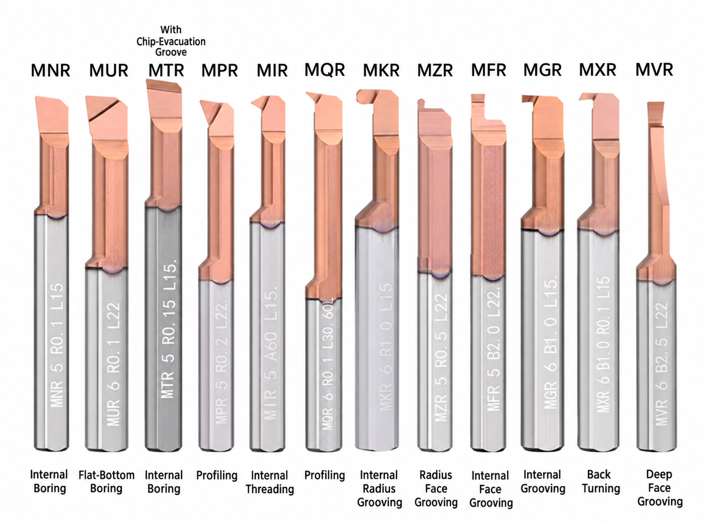
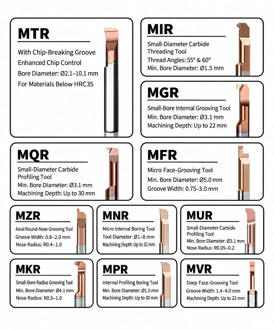
Related Micro Internal Tooling Series
Internal Threading: MIR / MIL Series
Internal Grooving: MGR Series
Radius Grooving: MKR Series
Micro Boring: MTR Series
Micro Internal Tooling Catalog
View the complete micro boring, grooving, profiling and threading tool range in the HY Micro Internal Tooling Catalog (PDF).
We support distributors, tooling suppliers and industrial partners with flexible OEM and private label solutions for micro internal tooling products. From laser marking and customized packaging to product identification and technical documentation, we help customers build their own tooling product lines with reliable manufacturing support.
OEM Product Scope
We provide OEM and private label manufacturing solutions for micro internal tooling products, supporting distributors and tooling suppliers with standard series, customized specifications and drawing-based production.
MPR series and customized small-diameter boring tools for precision internal machining and anti-vibration applications.
MIR/MIL series with customized thread profiles, dimensions and product identification requirements.
Internal grooving and special groove solutions for miniature precision components.
Non-standard dimensions, special geometries and customer drawing-based tooling solutions are available.

Customization Options
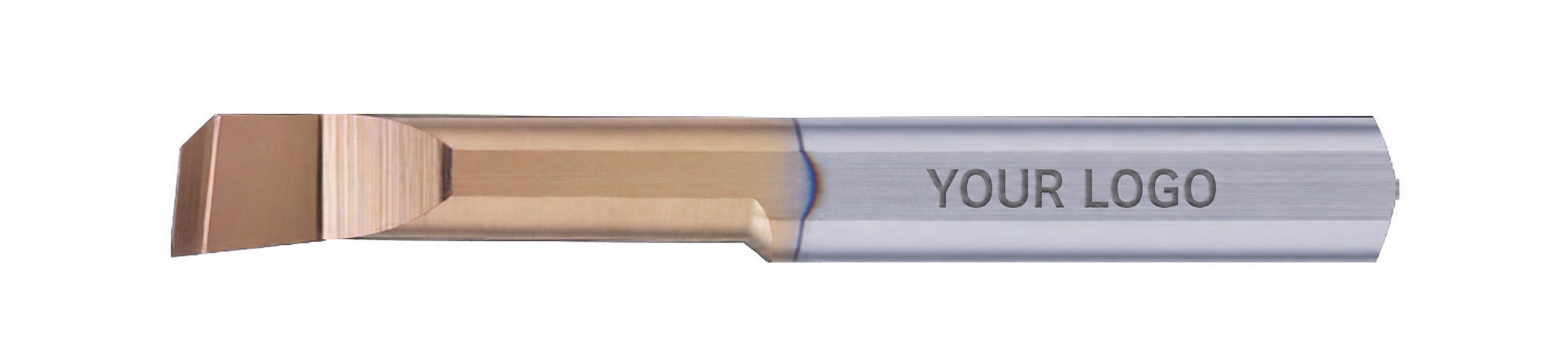
Laser Marking & Product Identification
Custom logo, model number and product identification marking can be provided according to distributor and brand requirements.
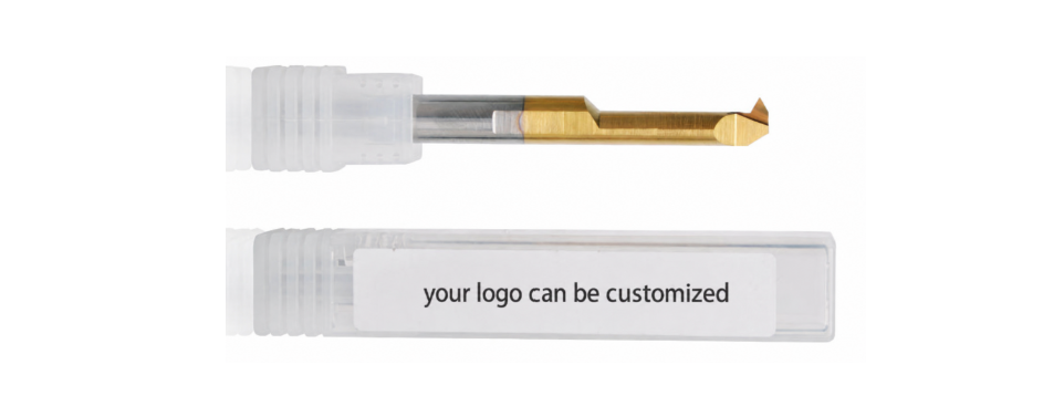
Custom Packaging
Individual packaging, labels and product information can be customized to support reseller sales channels and private brand development.
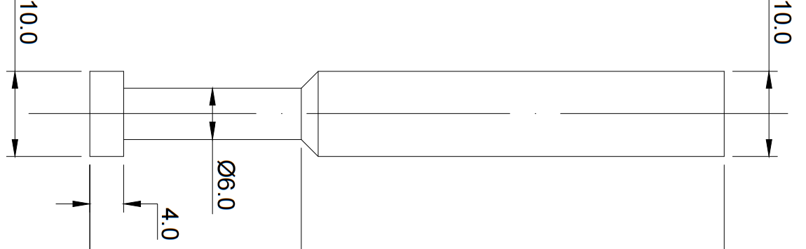
Technical Documents & Product Support
Support technical drawings, specifications and product information to help distributors promote and manage their tooling products.
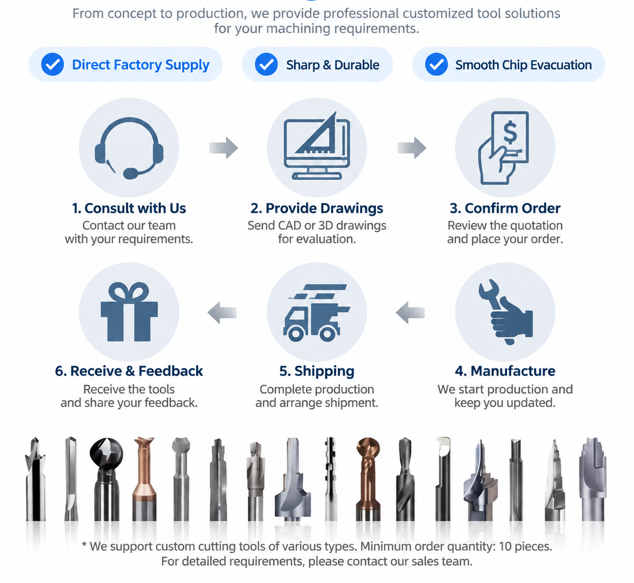
OEM Workflow
Confirm drawings, specifications, materials and packaging requirements.
Finalize tool design, marking details and production requirements.
Provide samples for testing and approval before batch production.
Produce and inspect according to confirmed requirements.
Private Label Support for Distributors
For distributors and tooling resellers, we provide flexible private label support including customized marking, packaging solutions and product documentation to help establish a professional tooling product range.
We follow strict quality control procedures from raw material inspection to final shipment. Each tool is inspected to ensure consistent dimensions, cutting performance and reliable quality for industrial machining applications.
Quality Control Process
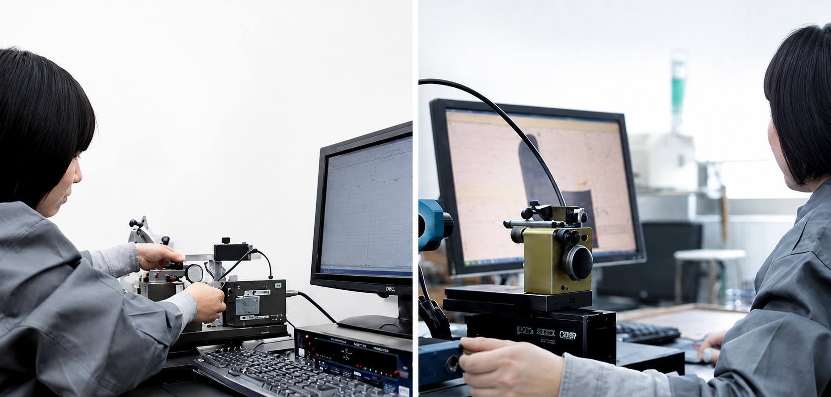
Verify carbide material quality and consistency before production.
Control tool geometry, dimensions and cutting edge accuracy during manufacturing.
Inspect edge quality and surface finish to maintain stable cutting performance.
Confirm product specifications before packing and shipment.
Inspection Standards
| Inspection Item | Purpose |
|---|---|
| Material Inspection | Verify carbide quality and material consistency. |
| Dimension Inspection | Confirm tool size and tolerance requirements. |
| Cutting Edge Inspection | Check edge geometry and surface quality. |
| Final Inspection | Ensure products meet confirmed specifications before delivery. |
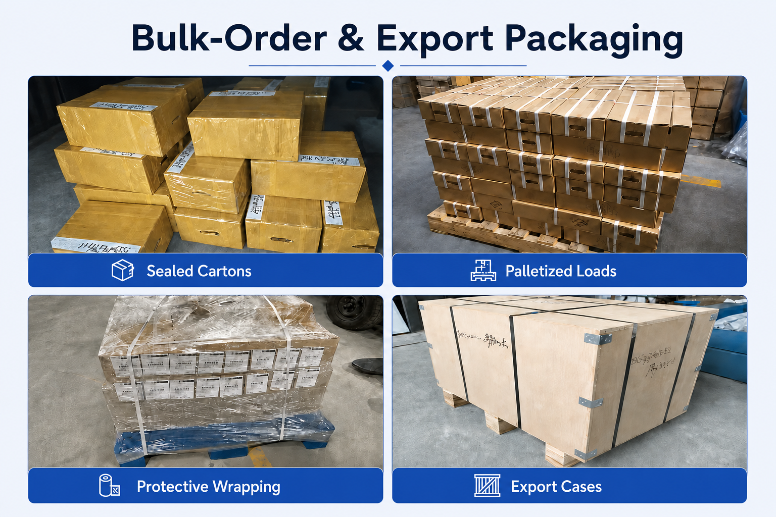
Packing & Protection

Individual protection and export packaging help prevent tool damage during storage and international transportation.
- Individual tool protection
- Product identification labels
- Batch traceability support
- Export shipment protection
Production & Delivery Workflow
Auftragsbestätigung
Production Scheduling
Quality Inspection
Packing
Shipment

Delivery Support
Standard products can usually be shipped within 1–3 working days after order confirmation. Customized products require confirmation according to tool design, quantity and production requirements.
FAQ & Downloads
Product FAQs
What are MDR micro thread relief grooving bars used for?
What is the difference between MDR and MDL tools?
What minimum bore diameters are available?
What is the standard cutting profile of the MDR series?
Is there an MDR version for stainless steel machining?
Selection & Application FAQs
How do I select the correct MDR model?
Does the 4, 5 or 6 in the model number indicate shank diameter?
Which MDR model should I use for my bore diameter?
How can I improve machining stability with an MDR tool?
How should I check tool clearance before machining?
Ordering & OEM FAQs
Can you manufacture custom MDR or MDL grooving bars?
What information is required for an MDR quotation?
Can I order mixed models or small quantities?
Is OEM marking and private-label packaging available?
What is the lead time for standard and customized MDR tools?
Technische Ressourcen
Need Sizes, Pricing or Custom Options?
Send us the required tool type, sizes, quantities, workpiece material and any OEM or custom requirements. We will confirm suitable specifications, availability, lead time and quotation details.
Drawings, size lists and reference photos are welcome.