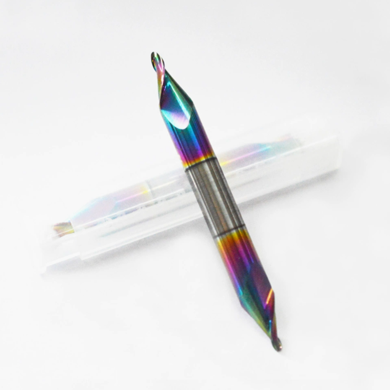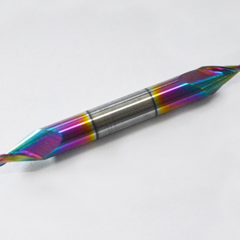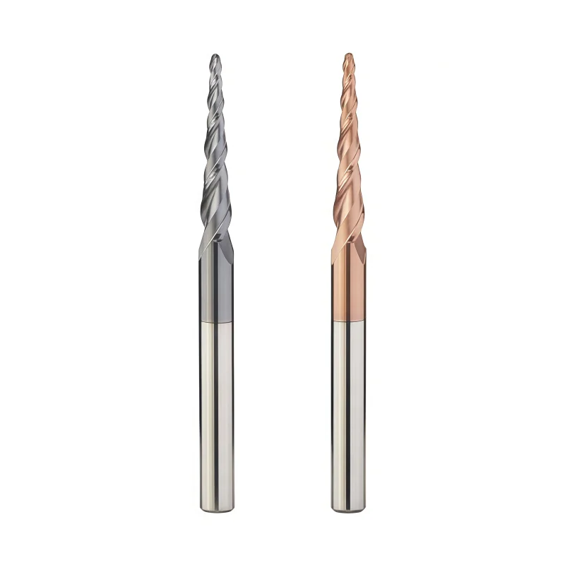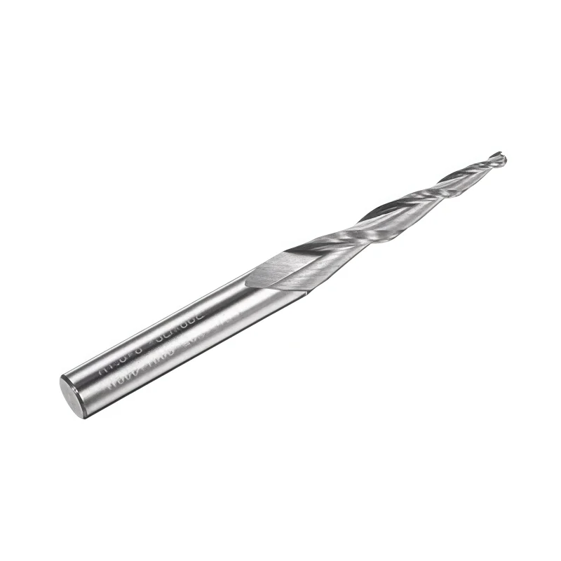
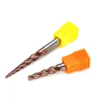
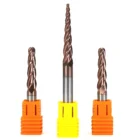
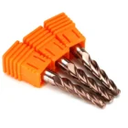
Ø6 mm Solid Carbide Tapered Ball Nose End Mill for Steel
Consistent Quality
Consistent geometry across repeat orders.
Flexible Bestellungen
Small batches and mixed sizes available.
OEM Support
Custom marking, labels and packaging.
Standard und Sonderanfertigungen
Standard sizes and custom configurations.
Ø6 mm Solid Carbide Tapered Ball Nose End Mill for Steel
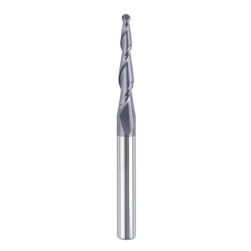
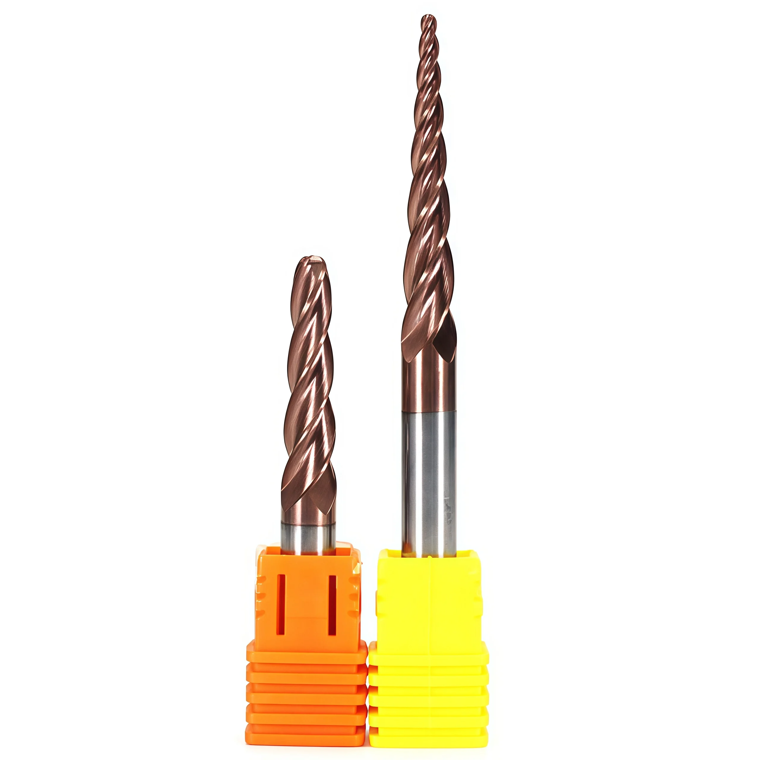
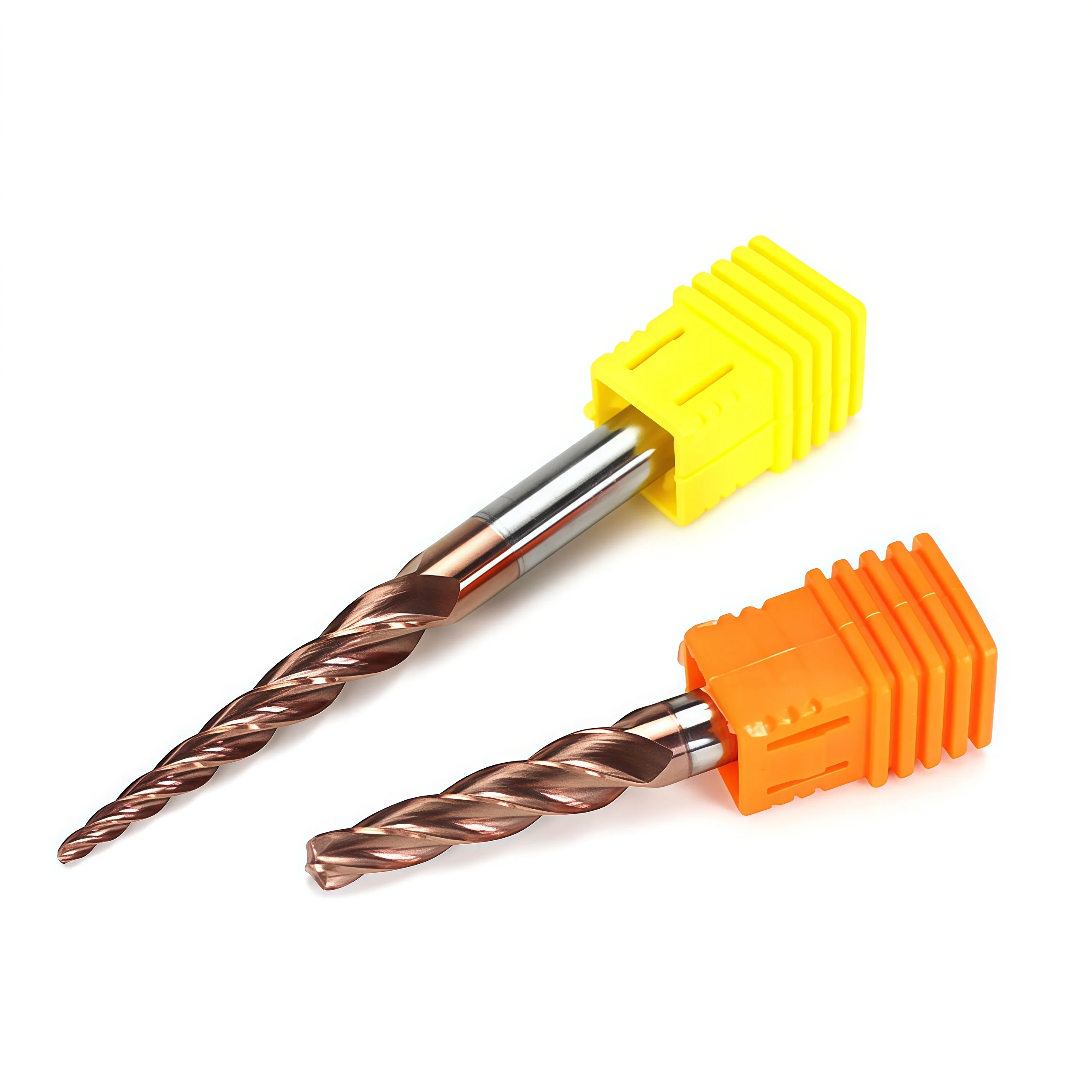
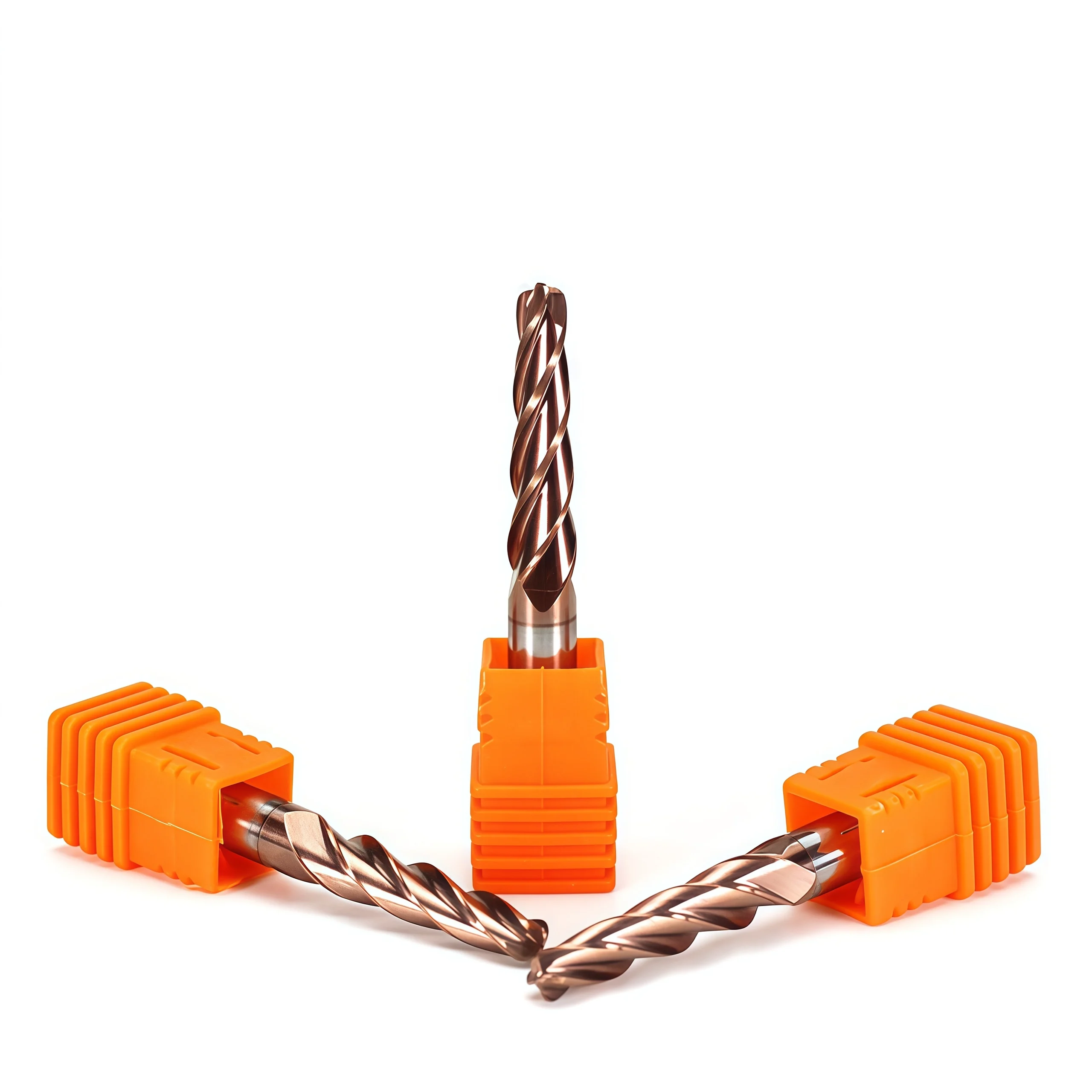
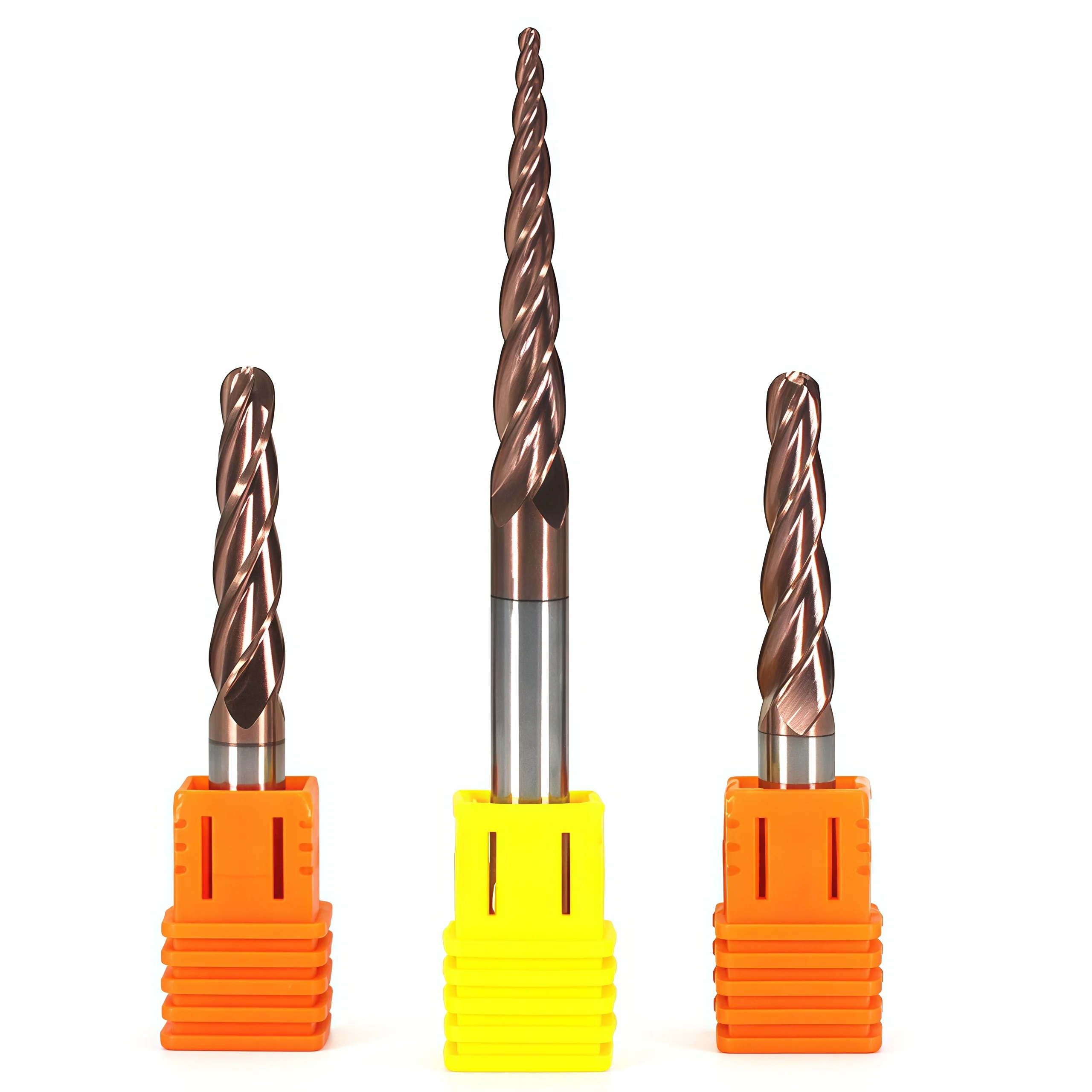
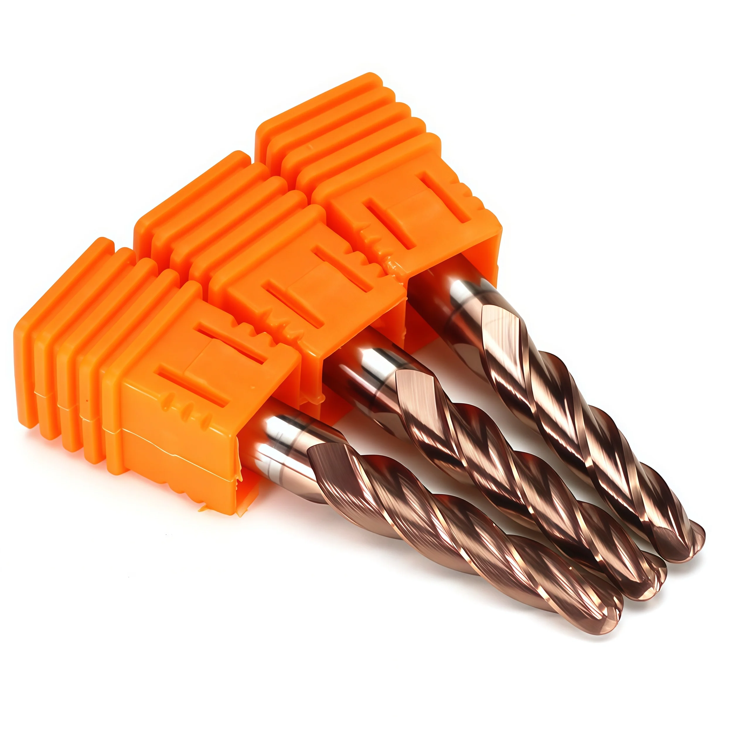
The TBN-6.0-H55-A is a 2-flute solid carbide tapered ball nose end mill developed for three-dimensional contouring and finishing in carbon steel, alloy steel and selected tool or mold steels. Its R3 ball nose follows curved and free-form surfaces, while the 3° included taper adds cross-sectional support behind the cutting edge for drafted walls, recessed profiles and detailed mold features. The defined Ø6 mm cutting diameter, 18 mm flute length, Ø6 mm shank and 75 mm overall length provide a clear single-model specification for distributors, tooling suppliers and repeat production orders.
Why This Geometry Is Different
Taper-Supported Reach
The 3° included taper adds material behind the cutting section, improving support when following drafted walls and recessed contours.
Full-Radius Surface Contact
The R3 ball nose maintains progressive contact across curved and blended surfaces for controlled 3D finishing toolpaths.
Application-Focused Advantages
2-Flute Cutting Geometry
Two flutes provide chip space while maintaining controlled engagement during steel contour finishing.
Fine-Grain Carbide
Solid carbide construction provides edge support and rigidity for repeatable CNC finishing.
Defined Single Model
A fixed D6 × R3 × 3° configuration reduces ambiguity during quotation and repeat ordering.
Coated Steel Configuration
The supplied AlTiN-TiN coating is intended to support wear and heat resistance in steel finishing.
Empfohlene Anwendungen
This model is intended mainly for controlled semi-finishing and finishing of steel components where both a rounded cutting profile and tapered side clearance are required.
Steel Material Compatibility
| MATERIAL | APPLICATION REVIEW |
|---|---|
| P Carbon Steel | General 3D contouring and profile finishing with application-matched cutting data |
| P Alloy Steel | Reduce engagement as strength, hardness, reach or tool contact increases |
| P Tool & Mold Steel | Suitable for selected mold-detail and curved-cavity finishing after hardness review |
Product Details & Machining Video
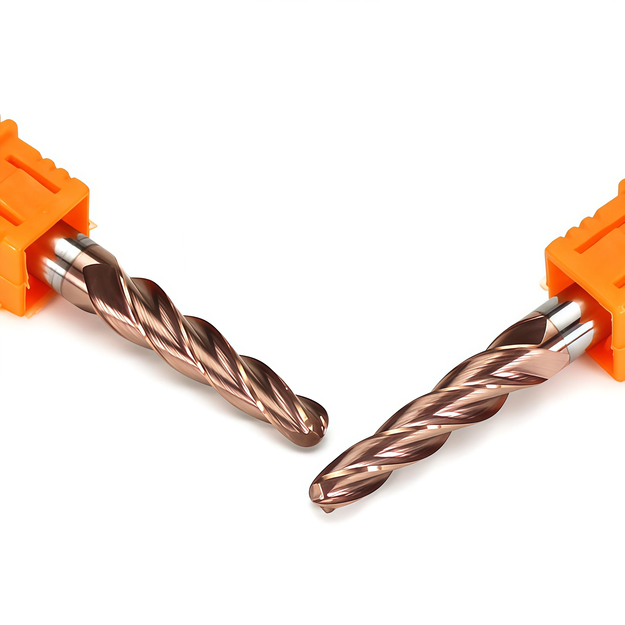
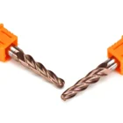
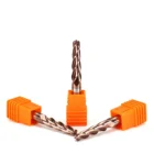
Detailed views of the cutting profile and tapered geometry, followed by a video position for a product or steel-machining demonstration.
TBN-6.0-H55-A Specifications & Dimensions
Dimensional and technical reference for the Ø6 mm, R3, 2-flute solid carbide tapered ball nose end mill for steel. All dimensions are in millimeters unless otherwise stated.

Standard Model Dimensions
| MODEL | D | R | α | L1 | d | L | FLUTES | HELIX |
|---|---|---|---|---|---|---|---|---|
| TBN-6.0-H55-A | 6.00 | 3.00 | 3° included | 18 | 6.00 h6 | 75 | 2 | 30° |
Technical Configuration
| PARAMETER | SUPPLIED SPECIFICATION |
|---|---|
| Werkzeug-Typ | Solid Carbide Tapered Ball Nose End Mill |
| Carbide Composition | WC-10%Co |
| Korngröße | 0.5–0.8 μm |
| Carbide Hardness | 1,650 HV30 |
| Diameter Tolerance | D6.00 ±0.003 mm |
| Radius Tolerance | R3.00 ±0.002 mm |
| Beschichtung | AlTiN-TiN, 3.5 μm |
| Primary Workpiece Group | Carbon steel, alloy steel and selected tool or mold steels |
| Primary Operations | 3D contouring, drafted-wall machining, curved-cavity and mold-detail finishing in steel |
Steel Application Reference
Select starting parameters according to the actual steel grade, hardness, ball-nose contact position, tool overhang and machining stage. Verified numerical cutting data was not provided for the steel configuration, so no universal RPM or feed value is stated here.
| MATERIAL GROUP | TYPICAL USE | PARAMETER FOCUS |
|---|---|---|
| P Carbon Steel | Curved profiles and 3D finishing | Effective diameter, step-over and chip evacuation |
| P Alloy Steel | Profile semi-finishing and finishing | Hardness, heat control and radial engagement |
| P Tool & Mold Steel | Mold cavities and drafted-wall finishing | Verified hardness, overhang, runout and surface-finish target |
Tapered Ball Nose Application Guidance
- Effective Diameter: Calculate cutting speed from the actual ball-nose contact diameter where possible.
- Step-Over: Select step-over according to R3 radius, surface curvature and finish requirement.
- Toolholding: Use a clean, low-runout precision holder and keep overhang as short as the feature permits.
- Taper Clearance: Verify the 3° included taper against the programmed wall angle and cavity clearance.
- Cooling & Chip Removal: Use the cooling method selected for the steel grade and maintain reliable chip evacuation.
Ø6 mm Tapered Ball Nose End Mill Customization
The standard TBN-6.0-H55-A configuration uses a Ø6 mm cutting diameter, R3 ball radius, 3° included taper, 2-flute geometry, 30° helix, 18 mm flute length, Ø6 mm shank and 75 mm overall length. Selected dimensional, geometric and coating adjustments can be reviewed for carbon steel, alloy steel and tool or mold steel applications. Custom configurations are confirmed according to the workpiece grade and hardness, cavity geometry, required reach, finishing allowance, surface-finish target and order quantity.
| PARAMETER | MANUFACTURING CAPABILITIES |
|---|---|
| Cutting Diameter | Standard model Ø6.00 mm; selected non-standard diameters can be reviewed according to the tool drawing and machining feature |
| Radius der Kugel | Standard R3.00 full-radius profile, with drawing-defined ball radius and profile accuracy available for technical review |
| Kegelwinkel | Standard 3° included taper; alternative taper angles can be evaluated for drafted walls, cavity clearance and tool-rigidity requirements |
| Flöte zählen | Standard 2-flute geometry for controlled chip space and stable engagement during steel contouring and finishing |
| Flute & Overall Length | Standard L1 18 mm and L 75 mm; drawing-defined cutting length, reach and overall length can be reviewed for recessed or deep-cavity features |
| Shank Configuration | Standard Ø6 mm h6 cylindrical shank, with selected shank diameter and clamping-length adjustments available according to the holder and drawing |
| Helix Geometry | Standard 30° helix; geometry adjustments can be reviewed according to steel grade, hardness, chip formation and finishing requirement |
| Ball Nose Geometry | Precision-ground full-radius cutting end for curved surfaces, blended profiles and 3D mold features, with center geometry matched to the intended toolpath |
| Edge Preparation | Cutting-edge preparation, gash geometry and edge condition can be matched to the steel hardness, cutting load and required balance between edge strength and surface finish |
| Coating Selection | Standard AlTiN-TiN coated configuration; alternative steel-milling coatings can be reviewed according to workpiece grade, hardness, cutting temperature and coolant conditions |
| Steel Application | Geometry can be reviewed for 3D contouring, drafted-wall machining, curved mold cavities, profile semi-finishing and precision finishing |
| Dimensional Tolerance | Standard reference tolerances are D6.00 ±0.003 mm and R3.00 ±0.002 mm; other diameter, radius, taper, runout and profile requirements are confirmed from the drawing |
OEM- und Eigenmarken-Dienstleistungen
OEM manufacturing and private-label supply options are available for industrial distributors, tooling brands and repeat-production customers. Laser identification, label content, protective packaging and coating presentation can be configured according to the approved product specification and order requirements.

Laser Etching
Custom logos, tool codes, cutting dimensions, coating identification and batch numbers can be marked according to the available shank area.
Custom Labels & Packaging
Individual protective tubes, product labels, specification details, colored packaging tubes and private-label packaging can be reviewed.
Commercial Terms
MOQ, sample evaluation, custom-size trials, repeat orders and scheduled supply programs are confirmed according to the selected configuration.
Technical Workflow
A structured review process is used to confirm standard, customized and private-label square end mill requirements before production.
Inquiry
Submit the material, hardness, milling operation, dimensions, tolerance and quantity.
Engineering
Review flute geometry, helix angle, edge preparation, coating, ap and ae.
Commercial
Confirm quotation, MOQ, sample requirements, production schedule and delivery terms.
Production
CNC grinding, end-face formation, edge preparation, coating and laser marking.
Qualitätskontrolle
Inspect diameter, flute length, shank, runout, square-end geometry and cutting edges.
Quality, Inspection & Delivery
Our solid carbide square end mills are controlled through material verification, precision grinding, in-process measurement and final inspection. Key dimensions, square-end geometry, cutting-edge condition, coating appearance and product identification are reviewed according to the approved specification or drawing before packing.

Three-Stage Quality Control
Inspection checkpoints are arranged around the manufacturing process to support dimensional consistency and repeat-order control.
Incoming Material Control
Carbide substrate grade, blank dimensions and supplied material information are checked against the production requirement.
In-Process Grinding Control
Cutting diameter, flute geometry, flute length, square-end profile and shank dimensions are monitored during CNC grinding.
Final Tool Inspection
Finished tools are reviewed for specified dimensions, runout, cutting-edge condition, coating appearance, marking and packing identification.
Key Inspection Characteristics
Inspection requirements are confirmed according to the standard product specification or the approved custom drawing.
| INSPECTION ITEM | CONTROL FOCUS | CONFIRMATION BASIS |
|---|---|---|
| Cutting Diameter (DC) | Diameter and dimensional consistency | Standard specification or approved drawing |
| Flute Length (APMX) | Effective cutting length | Confirmed product size or drawing requirement |
| Shank Diameter (DCON) | Clamping-section dimension and surface condition | Applicable shank specification |
| Overall Length (OAL) | Total tool length | Standard size matrix or approved drawing |
| Radial Runout | Concentricity between cutting section and shank | Agreed inspection requirement |
| Square-End Geometry | End-face profile, corner condition and center-cutting form | Selected tool configuration |
| Flute & Helix Profile | Flute count, helix form and grinding consistency | Approved manufacturing configuration |
| Cutting Edge & Coating | Edge condition, visible defects and coating appearance | Application-specific production requirement |
| Marking & Identification | Tool code, dimensions and batch information where applicable | Confirmed order and packaging specification |
Measurement & Batch Traceability
Optical measuring systems, tool inspection equipment and appropriate dimensional gauges are selected according to the feature being checked.
Optical Measurement
Profile and dimensional review of specified cutting features.
Runout Verification
Concentricity review based on the agreed product requirement.
Edge Inspection
Magnified review of the end face, corners and cutting-edge condition.
Batch Identification
Order, product and batch information are linked where required for repeat supply.
Protective Packaging Process
Finished end mills are protected to reduce contact between cutting edges and to support clear product identification during storage and transportation.

Bulk-Order & Export Packaging
Bulk shipments can be arranged with reinforced cartons, protective wrapping, palletized loading or export cases according to order quantity, shipment weight and agreed transportation requirements.

Delivery Coordination
Production completion, packing method and dispatch arrangements are confirmed according to the approved order. Courier, air, sea or customer-designated shipping options can be reviewed according to shipment size and destination. Final lead time is confirmed after product specifications, quantity and packaging requirements are approved.
Product & Application FAQs
Answers to common questions about selecting and applying the Ø6 mm Solid Carbide Tapered Ball Nose End Mill for Steel.
What materials is this ball nose end mill designed to machine?
What operations are suitable for the ball-nose profile?
How should step-over be selected for surface finishing?
Can the tool cut at the center of the ball nose?
What affects ball-radius and profile accuracy?
What is the advantage of a tapered ball-nose body?
Ordering & Customization FAQs
Information for distributors, tooling brands and customers requesting standard or application-specific ball-nose configurations.
What standard sizes are available?
Can non-standard dimensions or geometry be manufactured?
Are OEM marking and private-label packaging available?
What information is required for an accurate quotation?
Technical Downloads
Use the following references for product selection and starting cutting-data review.
Solid Carbide End Mill Catalog
Review related ball-nose, square-end, corner-radius and application-specific end mill series.
End Mill Speeds & Feeds Guide
Access reference starting parameters for application review and controlled machining trials.
Need a Size or Application Review?
Send the steel grade and verified hardness, required dimensions, machining operation and quantity for configuration and quotation review.
Need Sizes, Pricing or Custom Options?
Send us the required tool type, sizes, quantities, workpiece material and any OEM or custom requirements. We will confirm suitable specifications, availability, lead time and quotation details.
Drawings, size lists and reference photos are welcome.