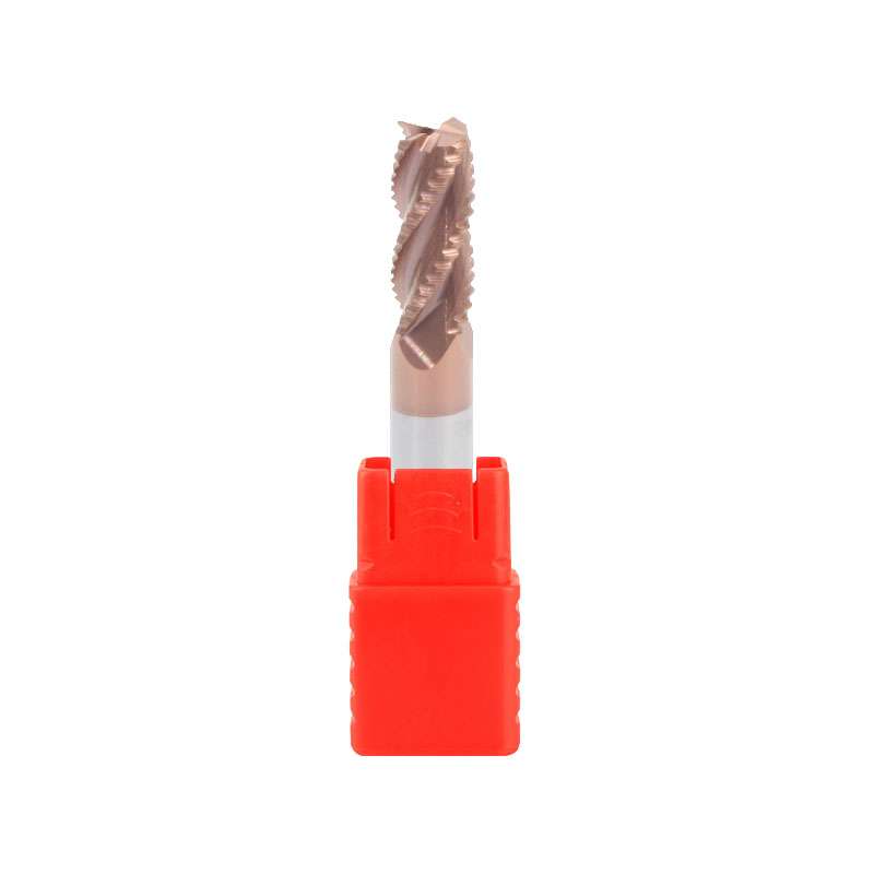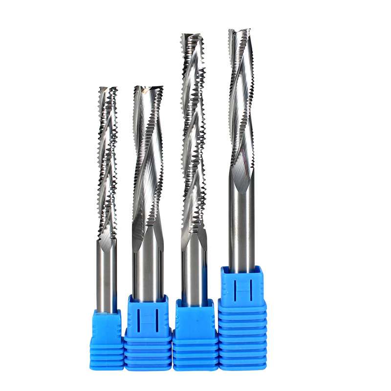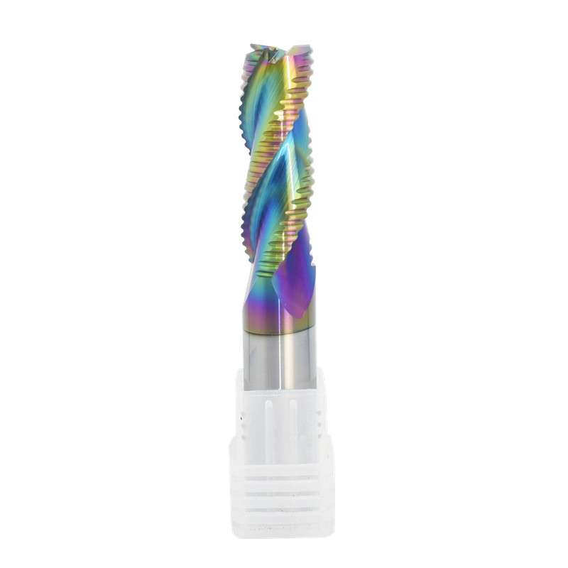
DLC-Coated 3-Flute Solid Carbide Roughing End Mill for Aluminum
Consistent Quality
Consistent geometry across repeat orders.
Flexible Orders
Small batches and mixed sizes available.
OEM Support
Custom marking, labels and packaging.
Standard & Custom
Standard sizes and custom configurations.
DLC-Coated Roughing End Mill Overview
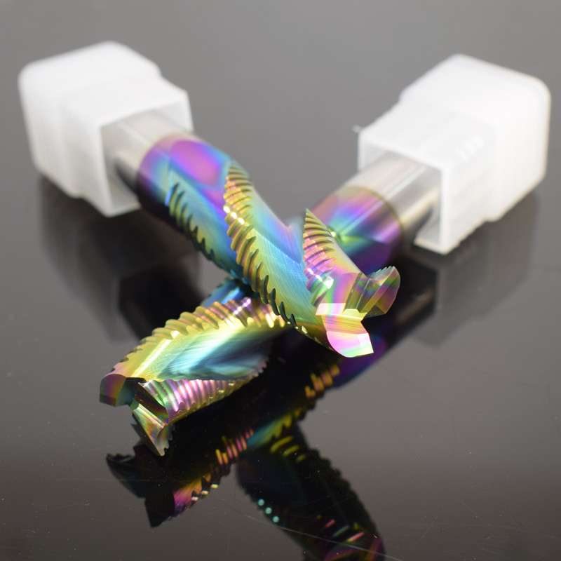
This DLC-coated 3-flute solid carbide roughing end mill is designed for efficient stock removal in aluminum alloys and selected non-ferrous materials. Its serrated wave-edge geometry divides the cutting load and produces shorter chips during high-engagement machining, while the three-flute construction provides sufficient chip space for aluminum roughing. The low-friction DLC surface helps reduce material adhesion and cutting-edge wear, supporting stable rough slotting, pocketing, side milling and profiling in repeat-production applications.
3 Flutes
Wave-Edge Roughing
DLC
Aluminum Alloys
DLC Aluminum-Roughing Features
Serrated Wave Edge
The roughing profile produces shorter chips and distributes the cutting load during high-engagement stock removal.
Three-Flute Chip Space
Three flutes balance tool-core rigidity, cutting contacts and flute capacity for evacuating larger aluminum chips.
Low-Friction DLC Coating
The DLC-coated surface helps limit aluminum adhesion, friction and cutting-edge wear during repeat-production machining.
Sharp Carbide Geometry
Application-matched rake and relief geometry support lower cutting resistance and controlled chip flow in aluminum.
Applications & Materials
Recommended for rough slotting, pocket roughing, side milling, profiling and high-engagement stock removal in aluminum components. The DLC-coated configuration is particularly suitable for repeat-production applications requiring controlled adhesion and consistent cutting-edge condition.
N Aluminum Alloys
N Cast Aluminum
N Copper Alloys
N Other Non-Ferrous
Product Details
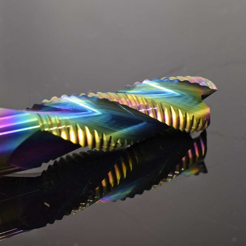

DLC-Coated Roughing End Mill Specifications
Technical configuration and standard reference sizes for the DLC-coated 3-flute solid carbide roughing end mill for aluminum. Dimensions are shown in millimeters. The cutting system combines serrated roughing geometry, aluminum-focused flute space and a low-friction DLC surface for efficient stock removal and controlled material adhesion.
| PARAMETER | STANDARD CONFIGURATION |
|---|---|
| Product Type | DLC-coated solid carbide roughing end mill for aluminum |
| Substrate | Fine-grain solid carbide |
| Flute Count | 3 flutes |
| Cutting Profile | Serrated wave-edge roughing geometry |
| End Profile | Flat / square end |
| Coating | DLC diamond-like carbon coating |
| Cutting Diameter | Ø1–Ø20 mm reference range |
| Shank Diameter | Ø4–Ø20 mm or drawing-defined configuration |
| Overall Length | 50–100 mm reference sizes; extended lengths can be reviewed separately |
| Helix Direction | Right-hand cutting and right-hand helix |
| Suitable Materials | Aluminum alloys, cast aluminum and selected copper alloys or other non-ferrous materials |
| Main Applications | Rough slotting, pocket roughing, side milling, profiling and high-engagement stock removal |
| Machine Compatibility | CNC machining centers and milling machines with effective chip evacuation |
Standard Reference Sizes
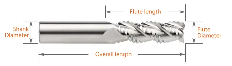
D = cutting diameter, L1 = flute length, d = shank diameter and L = overall length. The parameter image and dimensional combinations are retained from the previous 3-flute aluminum roughing end mill configuration.
| SPECIFICATION | D | L1 | d | L | FLUTES |
|---|---|---|---|---|---|
| D1–D4 × L1 × d4 × 50L | 1–4 | 3 / 6 / 9 / 12 | 4 | 50 | 3 |
| D4 × 16 × d4 × 75L | 4 | 16 | 4 | 75 | 3 |
| D4 × 20 × d4 × 100L | 4 | 20 | 4 | 100 | 3 |
| D6 × 15 × d6 × 50L | 6 | 15 | 6 | 50 | 3 |
| D6 × 24 × d6 × 75L | 6 | 24 | 6 | 75 | 3 |
| D6 × 30 × d6 × 100L | 6 | 30 | 6 | 100 | 3 |
| D8 × 20 × d8 × 60L | 8 | 20 | 8 | 60 | 3 |
| D8 × 25 × d8 × 75L | 8 | 25 | 8 | 75 | 3 |
| D8 × 35 × d8 × 100L | 8 | 35 | 8 | 100 | 3 |
| D10 × 25 × d10 × 75L | 10 | 25 | 10 | 75 | 3 |
| D10 × 40 × d10 × 100L | 10 | 40 | 10 | 100 | 3 |
| D12 × 35 × d12 × 75L | 12 | 35 | 12 | 75 | 3 |
| D12 × 45 × d12 × 100L | 12 | 45 | 12 | 100 | 3 |
| D14 × 45 × d14 × 100L | 14 | 45 | 14 | 100 | 3 |
| D16 × 45 × d16 × 100L | 16 | 45 | 16 | 100 | 3 |
| D18 × 45 × d18 × 100L | 18 | 45 | 18 | 100 | 3 |
| D20 × 45 × d20 × 100L | 20 | 45 | 20 | 100 | 3 |
DLC Coating & Cutting Configuration
The DLC coating, three-flute geometry and serrated cutting profile operate as a combined system for aluminum roughing. Final cutting performance also depends on chip evacuation, tool overhang, holder condition and machine rigidity.
| CONFIGURATION | APPLICATION FUNCTION |
|---|---|
| DLC Coating | Provides a low-friction surface that helps reduce aluminum adhesion and cutting-edge wear |
| Three-Flute Geometry | Balances cutting contacts, tool-core rigidity and chip space for aluminum stock removal |
| Serrated Roughing Edge | Produces shorter chips and distributes cutting load during rough slotting, pocketing and profiling |
| Sharp Carbide Edge | Supports lower cutting resistance and controlled shearing in aluminum and selected non-ferrous materials |
Aluminum Roughing End Mill Customization
Cutting diameter, serrated roughing-tooth profile, flute length, shank diameter, overall length, helix angle, cutting-edge geometry and surface treatment can be configured for aluminum-roughing applications. The standard design combines three flutes with polished chip channels and sharp cutting edges for controlled chip formation and efficient chip evacuation. Standard, long-flute, extended-length and drawing-defined configurations can be reviewed according to the aluminum grade, machining depth, tool engagement, spindle capability and required production efficiency.
| PARAMETER | MANUFACTURING CAPABILITIES |
|---|---|
| Cutting Diameter | Reference cutting diameters from Ø1–Ø20 mm, with intermediate and drawing-defined non-standard diameters available after technical review |
| Flute Count | Standard 3-flute construction balancing tool-core rigidity, cutting contacts and flute space for aluminum chip evacuation |
| Roughing-Tooth Profile | Serrated wave-edge pitch and tooth profile can be adjusted according to the cutting diameter, required chip size, cutting load and remaining finishing allowance |
| Flute Length | Standard, long-flute and drawing-defined cutting lengths can be reviewed according to the axial depth, workpiece geometry and required machining reach |
| Overall Length | Reference overall lengths of 50, 60, 75 and 100 mm, with selected extended-length configurations available for deep or less accessible features |
| Shank Configuration | Precision cylindrical shanks from Ø4–Ø20 mm, with custom shank diameter, reduced-neck geometry and clamping length reviewed according to the holder and tool overhang |
| Helix Geometry | Application-matched helix geometry selected according to the aluminum grade, cutting engagement, chip formation and required balance between edge strength and chip evacuation |
| End Geometry | Flat square-end geometry for rough slotting, pocketing and shoulder machining, with center-cutting capability confirmed by the selected configuration |
| Cutting-Edge Geometry | Sharp rake angle, relief geometry, end-face grinding and edge preparation can be matched to the aluminum grade, silicon content and cutting load |
| Flute Polishing | Polished flute surfaces support smooth chip flow and help limit friction, aluminum adhesion and chip recutting during continuous rough machining |
| Surface Treatment | Polished uncoated geometry is the standard configuration; DLC coating can be reviewed for lower friction and additional wear resistance |
| Workpiece Materials | Configurations can be reviewed for wrought aluminum, cast aluminum, aluminum alloys and selected copper alloys or other non-ferrous materials |
| Roughing Applications | Geometry can be configured for rough slotting, pocket roughing, side milling, profiling and high-engagement stock-removal operations |
| Coolant Method | Air blast, mist or aluminum-compatible coolant can be selected according to the machining engagement, chip volume and production conditions |
| Dimensional Tolerance | Drawing-defined control of cutting diameter, flute length, shank diameter, overall length, runout and roughing-edge geometry, with critical tolerances confirmed before production |
| OEM & Private Label | Customer logos, tool codes, dimensions, surface identification and batch numbers can be laser marked; custom labels, protective tubes and private-label packaging are also available |
OEM & Private Label Services
OEM manufacturing and private-label supply options are available for industrial distributors, tooling brands and repeat-production customers. Laser identification, label content, protective packaging and coating presentation can be configured according to the approved product specification and order requirements.

Laser Etching
Custom logos, tool codes, cutting dimensions, coating identification and batch numbers can be marked according to the available shank area.
Custom Labels & Packaging
Individual protective tubes, product labels, specification details, colored packaging tubes and private-label packaging can be reviewed.
Commercial Terms
MOQ, sample evaluation, custom-size trials, repeat orders and scheduled supply programs are confirmed according to the selected configuration.
Technical Workflow
A structured review process is used to confirm standard, customized and private-label square end mill requirements before production.
Inquiry
Submit the material, hardness, milling operation, dimensions, tolerance and quantity.
Engineering
Review flute geometry, helix angle, edge preparation, coating, ap and ae.
Commercial
Confirm quotation, MOQ, sample requirements, production schedule and delivery terms.
Production
CNC grinding, end-face formation, edge preparation, coating and laser marking.
Quality Control
Inspect diameter, flute length, shank, runout, square-end geometry and cutting edges.
Quality, Inspection & Delivery
Our solid carbide square end mills are controlled through material verification, precision grinding, in-process measurement and final inspection. Key dimensions, square-end geometry, cutting-edge condition, coating appearance and product identification are reviewed according to the approved specification or drawing before packing.

Three-Stage Quality Control
Inspection checkpoints are arranged around the manufacturing process to support dimensional consistency and repeat-order control.
Incoming Material Control
Carbide substrate grade, blank dimensions and supplied material information are checked against the production requirement.
In-Process Grinding Control
Cutting diameter, flute geometry, flute length, square-end profile and shank dimensions are monitored during CNC grinding.
Final Tool Inspection
Finished tools are reviewed for specified dimensions, runout, cutting-edge condition, coating appearance, marking and packing identification.
Key Inspection Characteristics
Inspection requirements are confirmed according to the standard product specification or the approved custom drawing.
| INSPECTION ITEM | CONTROL FOCUS | CONFIRMATION BASIS |
|---|---|---|
| Cutting Diameter (DC) | Diameter and dimensional consistency | Standard specification or approved drawing |
| Flute Length (APMX) | Effective cutting length | Confirmed product size or drawing requirement |
| Shank Diameter (DCON) | Clamping-section dimension and surface condition | Applicable shank specification |
| Overall Length (OAL) | Total tool length | Standard size matrix or approved drawing |
| Radial Runout | Concentricity between cutting section and shank | Agreed inspection requirement |
| Square-End Geometry | End-face profile, corner condition and center-cutting form | Selected tool configuration |
| Flute & Helix Profile | Flute count, helix form and grinding consistency | Approved manufacturing configuration |
| Cutting Edge & Coating | Edge condition, visible defects and coating appearance | Application-specific production requirement |
| Marking & Identification | Tool code, dimensions and batch information where applicable | Confirmed order and packaging specification |
Measurement & Batch Traceability
Optical measuring systems, tool inspection equipment and appropriate dimensional gauges are selected according to the feature being checked.
Optical Measurement
Profile and dimensional review of specified cutting features.
Runout Verification
Concentricity review based on the agreed product requirement.
Edge Inspection
Magnified review of the end face, corners and cutting-edge condition.
Batch Identification
Order, product and batch information are linked where required for repeat supply.
Protective Packaging Process
Finished end mills are protected to reduce contact between cutting edges and to support clear product identification during storage and transportation.

Bulk-Order & Export Packaging
Bulk shipments can be arranged with reinforced cartons, protective wrapping, palletized loading or export cases according to order quantity, shipment weight and agreed transportation requirements.

Delivery Coordination
Production completion, packing method and dispatch arrangements are confirmed according to the approved order. Courier, air, sea or customer-designated shipping options can be reviewed according to shipment size and destination. Final lead time is confirmed after product specifications, quantity and packaging requirements are approved.
DLC-Coated 3-Flute Roughing End Mill FAQ
Find answers about suitable materials, three-flute geometry, DLC coating, wave-edge roughing performance, cutting conditions, custom sizes, samples, lead time and OEM supply.
What materials can this roughing end mill machine?
What are the advantages of the 3-flute design?
How does the wave-edge geometry improve roughing performance?
What are the benefits of the DLC coating?
Can this cutter be used for finishing?
Can it perform full-width slotting?
Should air blast or coolant be used?
Is this DLC-coated end mill suitable for steel?
Can you manufacture custom sizes?
Can I order samples before bulk production?
What is the production lead time?
Do you provide OEM and private-label services?
What information is required for a quotation?
Technical Downloads
Download general product and cutting-data references for solid carbide end mill selection and machining preparation.
Need Sizes, Pricing or Custom Options?
Send us the required tool type, sizes, quantities, workpiece material and any OEM or custom requirements. We will confirm suitable specifications, availability, lead time and quotation details.
Drawings, size lists and reference photos are welcome.