
Spot Drill vs Center Drill: Which Tool Should You Choose?
A customer asks for a “center drill” and sends a diameter. Before quoting, you need to know whether the job is starting a drilled hole, supporting a shaft on a lathe, or cutting a chamfer. Those requirements can call for different angles and tool profiles.
The spot drill vs center drill decision starts with the next operation and the hole shape it needs. The examples below show how to turn a customer’s request into a tool choice and a clearer quotation.
Table of Contents — Browse article sections
Spot Drill vs Center Drill: The Main Difference
A spot drill creates a shallow locating recess for a following drill. Its short cutting section helps establish the starting position. A conventional center drill, also called a combined drill and countersink, has a small drilling pilot ahead of a larger conical cutting section.
For traditional lathe-center support, the wider cone commonly has a 60° included angle. The small pilot creates clearance for the center tip. Its drill-point angle is a separate feature, so “point angle” and “support-cone angle” should be identified separately on the drawing.

Catalog terminology varies. A tool sold as a “center drill” may be intended for centering or a particular combined hole form. Use its profile drawing to establish what it will actually cut.
Choose by the Next Operation
Start with the operation in the left column. It identifies the tool family and the information that will narrow the choice.
Then add the workpiece material and any current tool model or hole drawing. Our solid carbide drill selection guide covers the wider drilling requirements, including when a specified spot or pilot is needed.
Example: A Shaft Needs a 60° Center-Support Hole
Customer need
the drawing calls for a 60° seating cone and a Ø2 mm pilot. The customer asks for a “2 mm centering drill.”
Tool choice
send the center-hole detail to the supplier and ask for the tool drawing against that detail. Select the tool by its Ø2 mm pilot and seating cone; a 2 mm spot-drill cutter diameter describes a different feature.
Quote wording
list “pilot Ø2 mm; 60° seating cone; hole form and pilot depth to attached drawing,” followed by the selected body diameter, overall length and tool model. Resolve any missing drawing dimensions before approving the tool.
Example: A Ø6 mm Hole Needs a C0.5 × 45° Chamfer
Calculation
for a Ø6 mm round hole perpendicular to a flat face, a 0.5 mm radial chamfer leg at 45° gives a nominal opening diameter of Ø7 mm: 6 + (2 × 0.5). The 0.5 mm is the leg size, not the diagonal face width.
Cutting range
look for a 90° included-angle chamfering tool whose usable conical cutting edge covers Ø6–Ø7 mm. A tool’s nominal diameter alone does not establish this range.
Inquiry wording
“Chamfer an existing Ø6 mm hole to C0.5 × 45° after drilling; material [grade]; tool quantity [pieces].” This separates the chamfering requirement from any spotting needed before drilling.
Match the Spot Angle to the Following Drill
For conventional carbide-drill spotting, a common guideline is a spot angle equal to or slightly greater than the following drill’s point angle. The aim is engagement near the center before the outer cutting region. Use the entry procedure recommended for the actual drill series.
These examples depend on the following drill. An unsuitable recess can make a carbide drill contact away from its center first, increasing the risk of edge damage. A 90° spot can also suit some HSS/HSCO applications, including the relatively large-chisel-edge case described by Gühring. Choose from the actual drill geometry and instructions.
Spot diameter and depth also affect entry. Deep-hole and micro-drilling systems may require a cylindrical pilot hole rather than a shallow conical spot. Curved or inclined entry faces may need another preparation method. Describe those conditions with the inquiry.
Example: The Following Drill Is Ø8 mm Carbide with a 140° Point
Starting point
identify the drill series and its entry instructions. If it is intended for direct entry on the actual surface, follow that process. If it calls for spotting, select the spot around that requirement.
Spot choice
a 142° spot is one option to assess for this 140° drill. Send the supplier the Ø8 mm drill model and workpiece material, and use the drill series’ requirements for spot size and depth. The spotting tool does not have to be Ø8 mm simply because the following drill is Ø8 mm.
Order detail
request an angle-matched spotting option instead of ordering a 90° model solely because it is available. Include the required spot angle in your inquiry to HY so the quotation identifies the proposed geometry.
Only Have a Tool Photo or Model Number?
Send it with the workpiece material and what happens next: drilling, center support or chamfering. We can help identify the tool type and the remaining details needed for selection.
Can These Tools Replace Each Other?
For an equivalent-tool request, collect the current model, a clear side photo and the required result. Put the essential dimensions and geometry on the quotation before comparing prices. A similar appearance does not establish an equivalent specification.
What to Send for Identification and Quotation
For Identification: Start with What You Have
For identification, send a clear side photo, a tip close-up or the current supplier’s model, together with the material and operation. Include the size and quantity if known. A photo helps narrow the tool family; it usually cannot establish exact angles, tolerances or a custom hole form.
For Quotation: Add the Tool Specifications
When comparing prices, line up the same tool material, geometry, dimensions and coating or uncoated condition. Then compare quantity, delivery and other quoted costs. Two tools with the same nominal diameter may still be different specifications.
For an initial trial, keep the confirmed model or drawing with the test material, setup and result. Evaluate the locating or center-hole feature the customer actually needs. Our cutting tool trial-order guide explains how to organize that first evaluation.
HY Cutting Tools Product Options
For steel spotting and small-pilot center-drilling requirements, start with these HY Cutting Tools ranges.
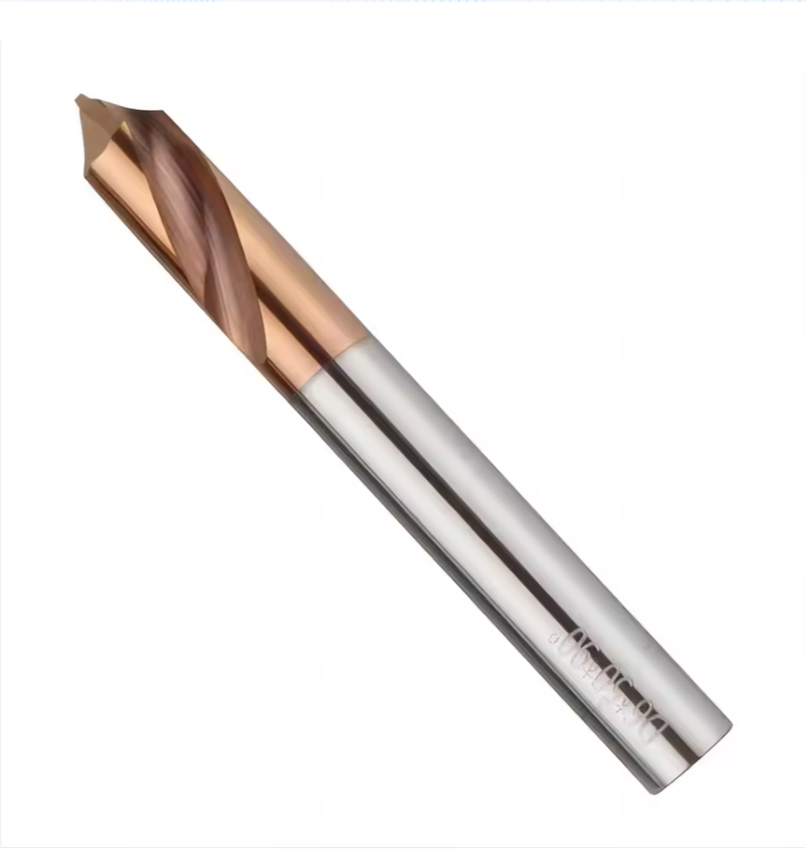
90° Carbide Spot Drill
For steel-focused spotting and selected light 45° chamfering. The HRC55 series covers Ø3–Ø12 mm cutting diameters. Select the configuration for the steel grade, hardness and required reach, then match any following drill.

Double-Ended Carbide Center Drill
Two usable cutting ends with Ø0.4–5 mm pilot diameters across the listed sizes. Send the required pilot and body dimensions. For center support, request a drawing that identifies the seating cone and drill point separately.
For other spotting and chamfering requirements, see the 60° / 90° / 120° carbide spot drill and chamfer mill range. It includes 2- and 3-flute configurations and reference cutting diameters of Ø2–Ø20 mm. Available combinations depend on size and application; specify the angle and operation with the inquiry.
For a drawing-defined center-hole profile or nonstandard dimensions, send the required form for assessment. You can also browse the full spot and center drill range.
Buyer FAQ
Does every carbide drill need a spot first?
Is a spotted recess the same as a pilot hole?
Why is a 3 mm center drill not always a 3 mm body?
Can one 90° tool handle spotting and 45° chamfering?
Can HY Cutting Tools identify a replacement from a photo?
What if my customer needs a special center-hole shape?
Technical References
Related Buying Guides

Cutting Tool Trial Orders
Plan the initial test before buying in bulk.
Choose a Solid Carbide Drill
Match the following drill to the material, hole depth and setup.
Find the Right Spot or Center Drill
Start with a tool photo or model number, the workpiece material and the required operation. Add the sizes and quantities you know. We can help identify the remaining information needed to select and quote a suitable configuration.