
How to Choose a Reamer: Size, Tolerance and Geometry Guide
Knowing how to choose a reamer starts with the finished hole—not with a coating color or an “H7” label.
A reamer is part of a complete process that includes the pre-hole, cutting allowance, machine alignment, holder, coolant, cutting data and inspection method.
This guide explains how to select a machine reamer by size, tolerance, flute geometry and operating conditions without assuming that one tool can hold the same result in every setup.
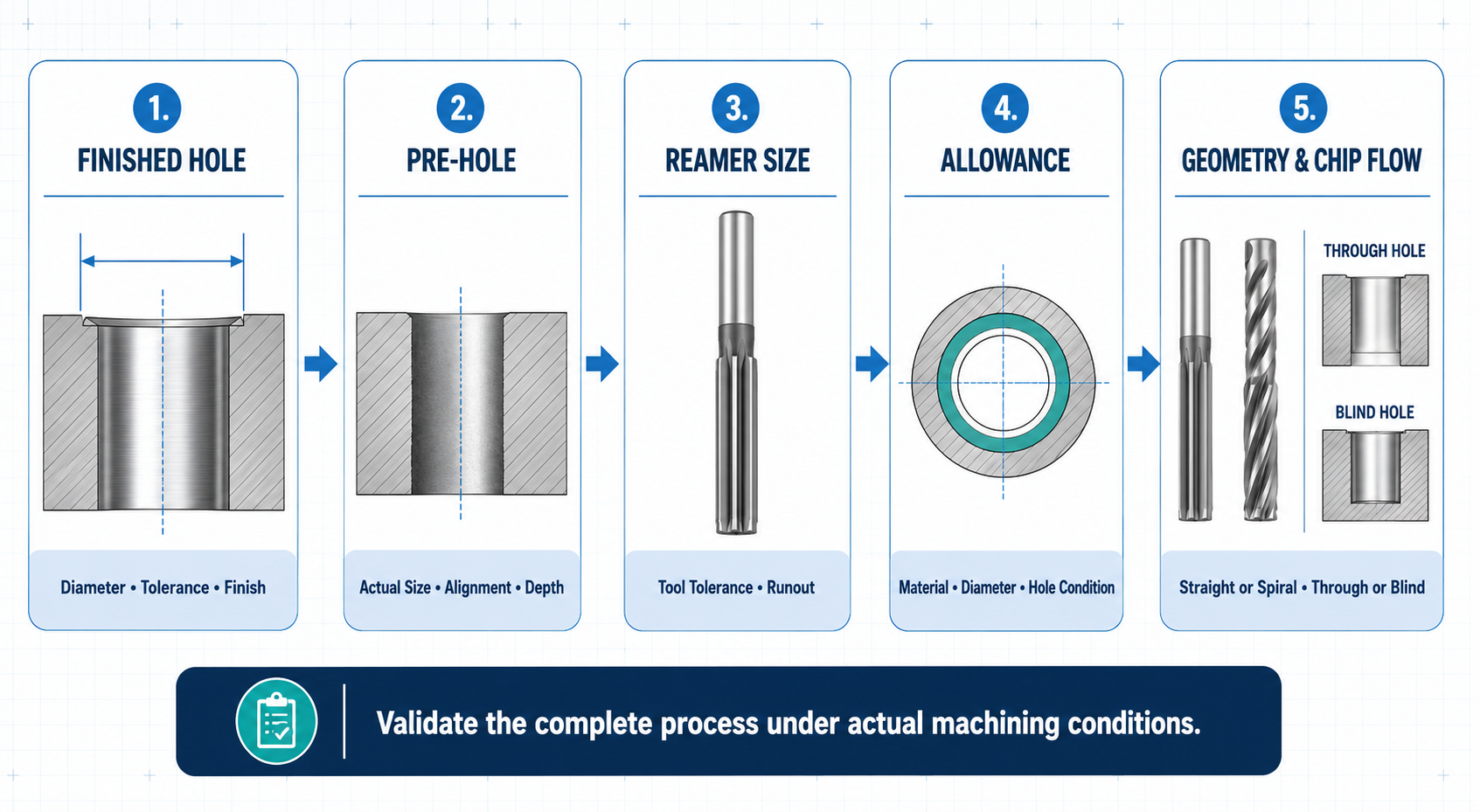
Quick Reamer Selection Table
Use this table to narrow the options, then confirm the exact diameter tolerance, allowance and cutting data for the selected tool series.
| Applicazione | Practical Starting Choice | Main Point to Confirm |
|---|---|---|
| Short general-purpose through hole | Straight-flute machine reamer | Chip space, actual pre-hole and runout |
| Blind or deeper hole | Right-hand spiral, right-hand cut | Chip evacuation toward the entrance and bottom clearance |
| Through hole in steel or cast iron | Left-hand spiral, right-hand cut | Clear space for chips to move forward |
| Rigid CNC production | Solid carbide machine reamer | Low runout, stable clamping and coolant delivery |
| Lower-volume or less-rigid work | HSS or cobalt-HSS machine reamer | Toughness, speed range and reconditioning economics |
| Close-tolerance H7-class application | Tool series sized for the required tolerance band | Actual cutting-diameter tolerance and process trial |
Swipe horizontally to view the complete table.
1. Understand What a Reamer Can—and Cannot—Do
A reamer is a multi-edge finishing tool that removes a small, controlled amount from a drilled or bored hole. Correctly applied, it can improve diameter control and surface quality.
It normally follows the existing bore. It cannot reliably relocate a centerline or correct serious drill wander, angular error or curvature. Boring or another corrective operation may be required first.
Pre-hole variation, bell-mouth, burrs and alignment all affect the result. If the drilling operation is still being defined, review our solid carbide drill selection guide before finalizing the reamer.
2. Start with the Finished Hole Specification
Before selecting a catalog number, define the drawing and process requirements.
| Required Information | Why It Changes the Reamer Choice |
|---|---|
| Finished diameter and tolerance | Sets the process window and cutting-diameter range |
| Depth and diameter-to-depth ratio | Affects rigidity, flute length, coolant and chip evacuation |
| Through or blind hole | Determines chip direction and bottom clearance |
| Material, hardness and condition | Affects geometry, substrate, coating and cutting data |
| Interrupted bore, keyway or cross-hole | Changes cutting stability and edge loading |
| Finish and geometric tolerances | May require tighter control of runout, allowance and inspection |
| Machine, holder and coolant | Determines whether the tool can run as designed |
Swipe horizontally to view the complete table.
For a blind hole, distinguish total drilled depth from required full-diameter reamed depth. The lead or chamfer does not produce full diameter to the physical tip, so include adequate bottom clearance.
3. Choose the Right Reamer Type
Construction depends on machine rigidity, diameter, production volume and whether controlled adjustment is required.
| Reamer Type | Typical Selection Logic |
|---|---|
| Solid carbide machine reamer | Rigid CNC production and good wear resistance; requires low runout |
| HSS or cobalt-HSS machine reamer | Lower volume or less-rigid conditions where toughness matters |
| Carbide-tipped or modular reamer | Selected larger diameters and production systems |
| Expandable or adjustable reamer | Limited compensation within the manufacturer’s stated range |
| Hand reamer | Manual fitting and repair—not normal CNC production |
| PCD reamer | High-volume machining of suitable abrasive non-ferrous materials or composites |
Swipe horizontally to view the complete table.
Solid carbide is a common starting point for a stable CNC process. HSS is not limited to soft materials; its toughness can help where handling or alignment is less controlled. Review our solid carbide threading and reaming tools for standard and customized options.
4. Select Reamer Size and Tolerance Correctly
Select cutting diameter from the finished-hole limits and the manufacturer’s actual tool tolerance. A nominal 10.000 mm reamer need not measure exactly 10.000 mm, and its manufacturing tolerance is not the hole tolerance.
OSG lists cutting-diameter tolerances separately for its carbide chucking reamers; exact limits vary by series and diameter.
The finished bore can differ from tool diameter because of runout, material recovery, built-up edge, heat, wear and alignment.
Use This Size-Selection Sequence
- Calculate the upper and lower hole limits from the drawing standard and nominal size.
- Check the supplier’s actual cutting-diameter tolerance—not only the nominal label.
- Confirm the pre-hole, holder, runout, coolant and cutting data.
- Trial the tool in the real material and inspect size, form and finish.
- If the process misses the window, correct the variation or evaluate an adjustable or custom solution.
5. Determine the Correct Reaming Allowance
Reaming allowance is the diametral stock removed by the reamer:
Allowance = Reamer Cutting Diameter − Actual Pre-hole Diameter
Use measured pre-hole diameter, not only nominal drill size. A drilled hole may be oversize, tapered, lobed or wandering, making the stock uneven.
- Too little allowance can cause rubbing, poor finish, rapid wear and inconsistent size.
- Too much allowance increases load, heat and chip volume, risking packing, chatter or tool damage.
No single allowance suits every reamer. Diameter, material, depth, geometry, substrate and finish all matter. Follow the recommendation for the exact tool series and validate it in the actual process.
6. Match Flute Geometry to Hole Type and Chip Flow
Geometry should move chips toward free space without sacrificing guidance or edge strength. For a spiral reamer, state both the cutting hand e helix direction; “right-hand reamer” alone is ambiguous.
| Geometria | Chip-flow Tendency | Common Starting Application |
|---|---|---|
| Straight flute, right-hand cut | Limited axial chip transport | General work, short through holes and short-chipping materials |
| Right-hand spiral, right-hand cut | Tends to draw chips toward the entrance | Blind or deeper holes and long-chipping materials |
| Left-hand spiral, right-hand cut | Tends to push chips forward | Through holes with clear chip space ahead of the tool |
Swipe horizontally to view the complete table.
These are tendencies, not universal rules. Supplier geometry, coolant-outlet design and application data take priority. Kennametal’s reaming guide gives additional manufacturer guidance on flute direction and chip flow.
Other Geometry Details to Check
- Lead or chamfer: performs much of the cutting and affects load, entry and full-diameter blind-hole depth.
- Flute count: more flutes can support more total feed but leave less chip space.
- Flute spacing: unequal spacing may reduce chatter but cannot correct runout or weak clamping.
- Cutting length and neck clearance: must clear the depth and part features without excess overhang.
- Margin and back taper: affect guidance, friction and size control and are tool-family specific.
7. Match Tool Material and Coating to the Application
Choose the substrate and edge geometry before treating coating as the deciding factor.
| Materiale dell'utensile | Strengths | Main Cautions |
|---|---|---|
| HSS / cobalt HSS | Tough, economical and more forgiving in lower-speed work | Lower hot hardness and wear resistance than carbide in many production applications |
| Solid carbide | High rigidity and wear resistance for stable CNC production | More sensitive to runout, shock and unstable workholding |
| Carbide-tipped / modular | Practical for selected larger diameters and production systems | Joint, cartridge or head accuracy must be controlled |
| PCD | High wear resistance in suitable non-ferrous and composite applications | Not a general solution for ferrous materials; higher cost and application limits |
Swipe horizontally to view the complete table.
Stainless steels need stable cutting that avoids rubbing and work hardening. Aluminum often benefits from sharp, low-adhesion geometry and effective evacuation. Cast iron is abrasive and usually short-chipping. Difficult alloys require a tool family validated for their heat and wear mechanisms.
Avoid these coating shortcuts:
- Treating HRC45, HRC55 or HRC65 as coating names
- Identifying coating chemistry only from gold, violet, blue or black appearance
- Selecting coating before confirming material, geometry, allowance and coolant
HRC labels usually describe an intended workpiece-hardness range or supplier series. Color does not reliably identify chemistry. Uncoated or polished carbide may suit some non-ferrous work, while selected wear-resistant coatings may benefit steels; neither is universal.
8. Check Toolholding, Runout and Coolant
Even a correctly sized reamer can fail in a poor setup. Sandvik Coromant’s reaming guidance emphasizes rigid workholding, a quality chuck, minimum overhang, correct pre-hole diameter and coolant reaching the cutting edges.
- Machine spindle condition and alignment
- Tool runout near the cutting edges
- Holder condition and minimum overhang
- Part clamping and bore-wall stability
- Coolant cleanliness, pressure and direction
- Unobstructed flute space and chip path
Internal coolant must suit the hole. For blind holes, it should help move chips back without trapping them at the bottom. For through holes, chips can often move forward. The strategy depends on outlet and flute design.
A floating holder can compensate for small axial or angular offset in specific applications, but should not hide excessive machine or fixture error. MAPAL describes floating holders as compensation devices for defined alignment conditions.
9. Set Starting Speeds and Feeds
Use the manufacturer’s data for the exact reamer, workpiece, coolant method and engagement. The formulas below convert those values into machine settings.
n = (1000 × Vc) ÷ (π × D)
vf = fn × n
vf = fz × z × n
As a broad starting heuristic, reaming often uses lower cutting speed and higher feed per revolution than drilling. Kennametal notes about one-half to two-thirds of drilling speed and two to three times its feed, but this is not a specification; exact tool data takes priority.
Enter smoothly, feed continuously and avoid dwelling. Do not peck unless the supplier recommends it. After a controlled trial, inspect chips, size, taper, finish and tool wear.
10. Troubleshoot Common Reaming Problems
Treat each symptom as evidence, not proof of one cause.
| Symptom | Likely Causes to Investigate First |
|---|---|
| Hole oversize | Runout, misalignment, built-up edge, unstable clamping, excess stock, damaged edge or wrong tool tolerance |
| Hole undersize or variable | Insufficient stock, rubbing, material recovery, wear, poor coolant, pre-hole variation or measurement error |
| Taper or bell-mouth | Misalignment, unstable entry, pre-hole taper, part deflection, excess overhang or uneven stock |
| Chatter or poor finish | Runout, low rigidity, unsuitable data, poor lead engagement, chip recutting or geometry mismatch |
| Chips packed in flutes | Wrong chip direction, inadequate flute space, excessive allowance, blocked coolant or unsuitable data |
| Rapid wear or breakage | Excess stock, interruption, wrong grade/geometry, poor lubrication, packing, runout or shock |
Swipe horizontally to view the complete table.
Change one controlled variable at a time. Confirm the drawing and measurement method, then inspect the pre-hole, tool, holder and alignment before changing reamer diameter.
11. How to Choose a Reamer: Final Checklist
For a reliable recommendation or quotation, prepare:
- Finished diameter, limits and standard
- Full-diameter depth and bottom clearance
- Through, blind, interrupted or cross-hole condition
- Material, grade, hardness and heat treatment
- Actual pre-hole diameter and variation
- Surface-finish and geometric requirements
- Machine, holder and measured runout
- Coolant type, delivery and pressure
- Current data, cycle target and batch size
- Inspection method and failure samples
Domande frequenti
Does an H7 reamer always produce an H7 hole?
No. H7 is the finished-hole tolerance zone. The result also depends on actual reamer diameter, pre-hole, runout, material behavior, wear, coolant and cutting data. The complete process must be proven.
How much material should a reamer remove?
Use the allowance specified for the exact tool series and application. There is no universal value for every diameter and material. Base it on the measured pre-hole.
Which spiral direction is normally used for a blind hole?
For a right-hand-cutting reamer, a right-hand spiral commonly draws chips toward the entrance. Confirm the tool design, coolant outlet and actual chip behavior.
Should I choose HSS or solid carbide?
Solid carbide suits rigid, low-runout CNC production where stiffness and wear resistance add value. HSS or cobalt HSS may be preferable when toughness, lower volume or less-rigid conditions matter more.
Can a reamer correct a misplaced or crooked hole?
Not reliably. A reamer normally follows the existing bore. Correct major position or straightness errors by improving drilling or using an appropriate boring operation first.