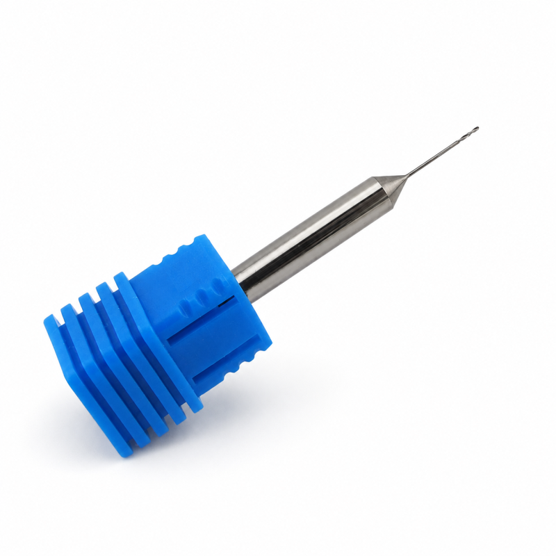
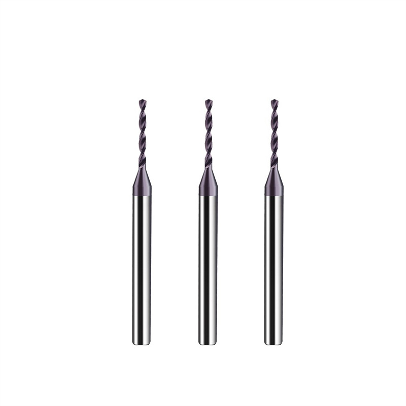
2-Flute Solid Carbide Micro Drill for Meltblown Spinneret Plates
Qualità costante
Consistent geometry across repeat orders.
Ordini flessibili
Small batches and mixed sizes available.
OEM Support
Custom marking, labels and packaging.
Standard e personalizzati
Standard sizes and custom configurations.
2-Flute Solid Carbide Micro Drill for Meltblown Spinneret Plates Overview
This 2-flute solid carbide micro drill is designed for repeated precision small-hole machining in meltblown spinneret plates, nozzle plates and similar multi-hole components. The confirmed standard range covers Ø0.25–2.00 mm cutting diameters, with practical 0.05 mm increments across the listed series and diameter-matched flute lengths. Fine-grain solid carbide and precision-ground 2-flute geometry support controlled entry, chip evacuation and repeatable hole production when used with low runout, short overhang and stable coolant, mist or air delivery.
Ø0.25–2.00 mm
0,05 mm
2 Spiral Flutes
Spinneret Plates
Key Configuration
2-Flute Micro Geometry
Two spiral flutes provide cutting-edge support and chip space for repeated small-hole production.
Diameter-Matched Flute Length
Flute lengths of 4.5, 5.0 and 7.0 mm are assigned by diameter group to limit unnecessary overhang.
Fine-Grain Solid Carbide
The carbide substrate provides the rigidity required for precision micro-drilling under a stable machine and holder setup.
Key Product Advantages
Precision-Ground Geometry
Controlled point and edge preparation support repeatable entry and consistent micro-hole production across multi-hole plates.
Optimized Tool Reach
Shorter flute lengths are matched to smaller diameters to reduce unnecessary reach and sensitivity to deflection.
Two-Flute Chip Evacuation
The spiral flute configuration provides chip space for blind, through and repeated micro-hole drilling under suitable coolant conditions.
Flexible Standard & Custom Supply
Standard diameter groups support replenishment, while shank size, geometry, coating and tolerances can be reviewed from customer drawings.
Workpiece Material Compatibility
Applications & Target Scope
- Meltblown spinneret hole production
- Nozzle and die plate micro holes
- Blind and through micro holes
- Repeated high-precision hole arrays
- Drawing-specific micro-hole production in selected plate materials
Product & Machining Details
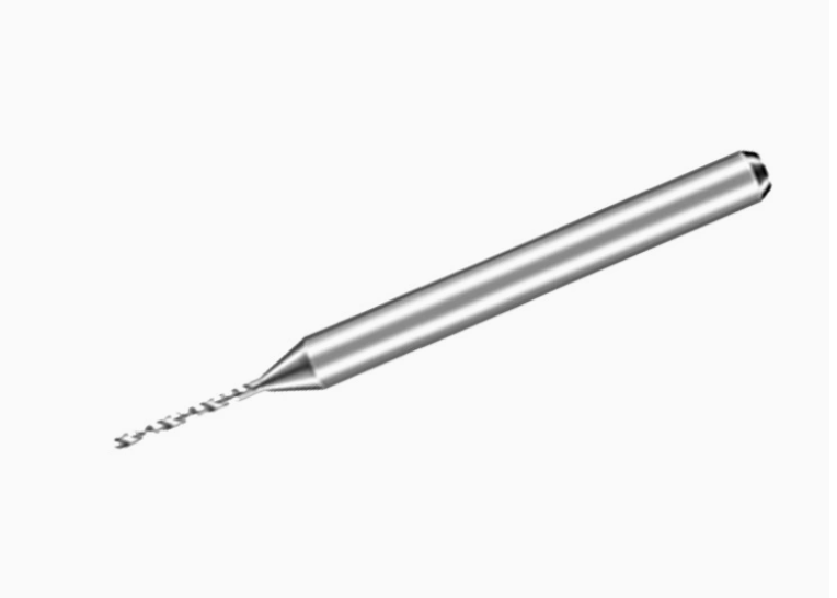
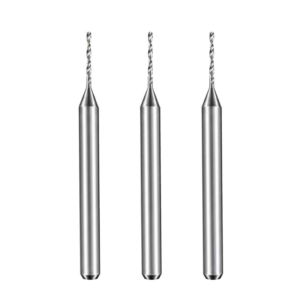
Tool Nomenclature & Dimensions
Standard reference configuration for the 2-flute solid carbide micro drill series for meltblown spinneret plates. The confirmed range covers Ø0.25–2.00 mm cutting diameters with 0.05 mm standard increments across the listed groups. Shank diameter, overall length, point geometry and tolerances should be confirmed from the selected specification or approved drawing.
Standard Size Matrix
The standard series is consolidated below by diameter range for faster selection while preserving the confirmed flute-length groups.
Spinneret Micro-Drilling Guidance
- Confirm Finished Hole Requirements: Provide hole diameter, tolerance, depth and blind- or through-hole type.
- Control Runout: Use a precision holder and verify runout close to the cutting edge before batch production.
- Use Minimum Practical Overhang: Select the shortest tool reach that clears the plate and fixture.
- Maintain Chip & Coolant Control: Direct coolant, mist or air consistently toward the cutting zone and avoid chip recutting.
Recommended Starting Cutting Parameters
Starting values should be selected for the exact spinneret plate grade, drill diameter, hole depth, coating, coolant delivery and machine rigidity. Begin conservatively, maintain stable feed without unnecessary dwell, and adjust only after checking hole quality, chip formation and tool wear.
Solid Carbide Drill Cutting Data Guide
Use the guide as a starting reference and adjust for micro diameter, hole depth, spinneret material and machine conditions.
Micro Drill Product Family Overview
Compare the workpiece, hole depth and production requirement before selecting the most appropriate micro-drill series.
Spinneret Micro Drill
Repeated Plate Holes (Current)
General Micro Drill
General Small Holes
Stainless Micro Drill
ISO M Applications
Custom Micro Drill
Drawing-Based Geometry
For additional drill sizes and related series, View the Solid Carbide Drill Catalog . Custom spinneret micro-drill configurations can be reviewed according to your drawing and production requirements.
Spinneret Micro Drill Customization
Cutting diameter, flute length, point geometry, edge preparation, coating and dimensional tolerance can be configured for precision micro-hole drilling in meltblown spinneret plates. The featured Ø0.3–0.6 mm range and 5 mm flute length support fine-hole production, while non-standard configurations can be reviewed according to the spinneret drawing, plate material and required hole specification.
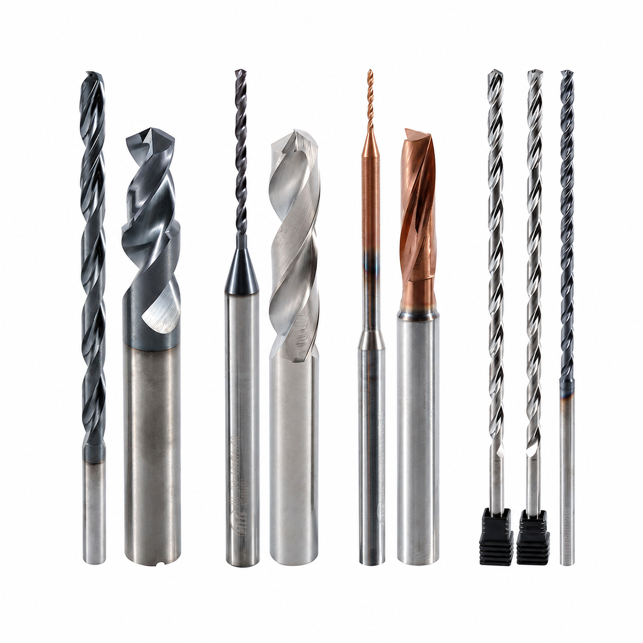
Micro-Hole Geometry & Edge Preparation
Two-flute geometry, micro-point form, web thickness, flute profile and cutting-edge preparation can be configured to support controlled entry, chip evacuation and consistent micro-hole formation in meltblown spinneret plates.
Servizi OEM e a marchio privato
OEM manufacturing and private-label supply options for spinneret manufacturers, precision-tool distributors and repeat-production customers.
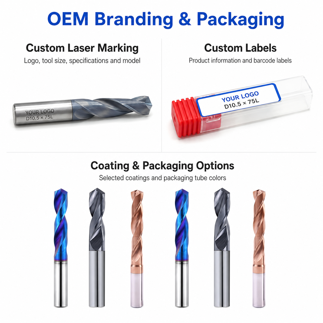
Tool Identification
Tool codes, diameter specifications and batch identification can be applied according to the available shank area.
Protective Packaging
Individual protective tubes, internal supports, diameter labels and private-label packaging help protect delicate micro cutting edges.
Commercial Terms
Flexible MOQ options for sample evaluation, custom-size trials, repeat orders and scheduled batch supply.
Technical Workflow
Inquiry
Submit the hole diameter, plate material, thickness, tolerance and required quantity.
Engineering
Micro-point geometry, flute length, edge preparation and coating are reviewed.
Commercial
Quotation, trial quantity, production schedule and delivery terms are confirmed.
Production
Precision micro-grinding, edge preparation, coating and tool identification.
Quality Control
Cutting diameter, flute length, point geometry, runout and cutting-edge condition are inspected before dispatch.
Inspection & Quality Control
Drill dimensions, cutting-edge geometry and visible surface condition are checked according to the confirmed product specification and application requirements.

Protective Packing for Shipment
Finished drills are protected individually before batch labeling and export-carton reinforcement.

Individual Tool Protection
Each drill is individually protected in a plastic tube to reduce contact damage during storage, handling and transportation.
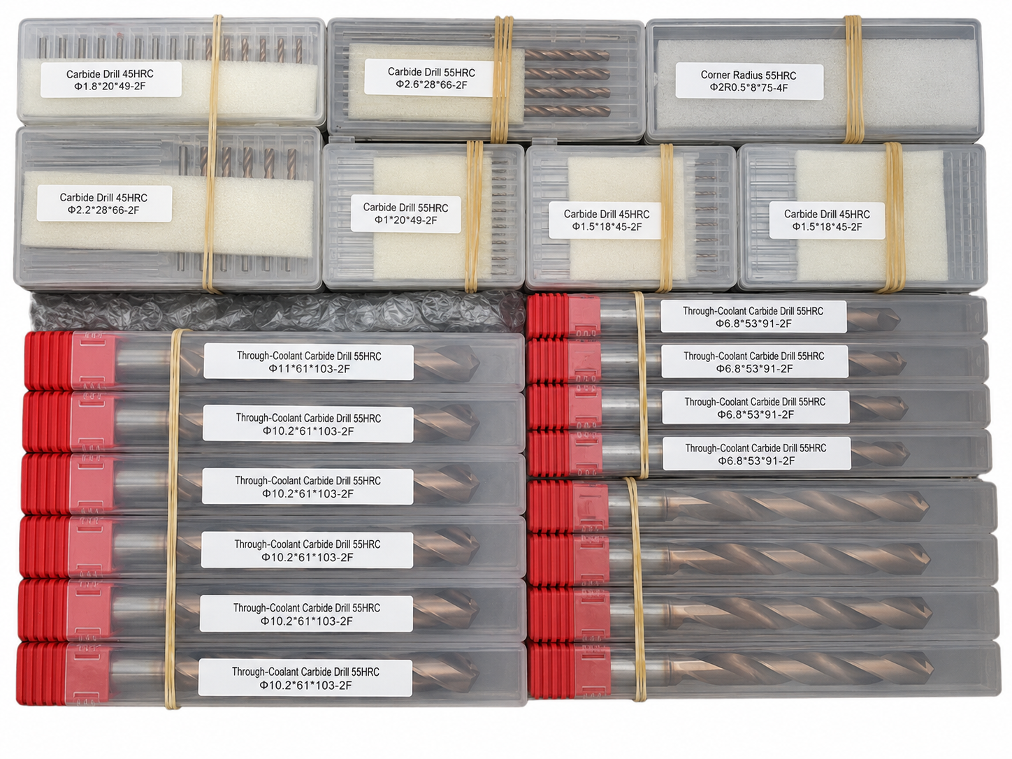
Batch & Label Verification
Tools are grouped and labeled by specification to support order verification before carton packing.

Export Carton Protection
Batch packaging, cushioning materials and reinforced export cartons are selected according to the order quantity and shipping method.
Reference Lead Time
The following timeframes are general references. Availability and production scheduling are reviewed for each order.
Shipping Options
Shipping arrangements can be selected according to order size, delivery schedule and destination.

Product FAQs
Product-specific information about micro-hole drilling in meltblown spinneret plates, available dimensions, chip evacuation, coolant requirements and custom drill configurations.
What is this micro drill used for in meltblown spinneret plates?
This 2-flute solid carbide micro drill is intended for machining precision small holes in meltblown spinneret plates and similar multi-hole components. The drill configuration should be matched to the required hole diameter, plate thickness, workpiece material and hole-quality requirements.
Why is a 2-flute geometry suitable for spinneret micro-hole drilling?
The 2-flute geometry provides cutting-edge support together with chip space for small-diameter drilling. In spinneret plate machining, stable chip evacuation and balanced cutting are important because a large number of closely controlled micro holes may need to be produced with consistent dimensions.
What diameters and lengths are available?
Standard sizes can be supplied according to the product size table, while non-standard cutting diameters, flute lengths, shank dimensions and overall lengths can be reviewed according to the spinneret plate drawing and required hole specifications.
How can burrs and inconsistent hole quality be reduced?
Low spindle runout, rigid toolholding, controlled feed, suitable drill geometry and stable chip evacuation are important for maintaining micro-hole quality. Tool condition and workpiece support should also be monitored when machining large numbers of closely spaced holes.
Can the geometry, coating and coolant method be customized?
Yes. Point geometry, edge preparation, flute configuration and coating can be reviewed according to the spinneret plate material, hardness, hole depth and required production volume. External coolant, mist or other suitable chip-removal methods can also be considered according to the machine setup.
What information is required for a quotation?
Please provide the required hole diameter, hole depth or plate thickness, workpiece material, hole tolerance, flute or reach requirement and estimated quantity. A spinneret plate drawing or hole specification is recommended for custom micro-drill quotations.
Ordering & OEM FAQs
General information for trial orders, mixed-size purchasing, private labeling and production scheduling.
Do you accept small trial orders?
Yes. Small trial orders are available for hole-quality testing, application verification and distributor evaluation before larger-volume purchasing.
Can mixed sizes be ordered together?
Yes. Different micro-drill diameters and length configurations can normally be combined in one order when production and coating requirements are compatible. This is suitable for distributors and customers evaluating multiple spinneret hole specifications.
Is OEM laser marking available?
Yes. Custom laser marking for logos, model numbers, tool sizes and batch identification can be reviewed together with private labels and OEM packaging requirements.
What is the typical production lead time?
Lead time depends on the cutting diameter, length, geometry, coating and order quantity. Custom micro drills may require additional time for drawing confirmation, grinding and inspection before shipment.
Downloads & Technical Resources
Access product dimensions, series information and starting cutting data for product selection and application review.
Need Sizes, Pricing or Custom Options?
Send us the required tool type, sizes, quantities, workpiece material and any OEM or custom requirements. We will confirm suitable specifications, availability, lead time and quotation details.
Drawings, size lists and reference photos are welcome.