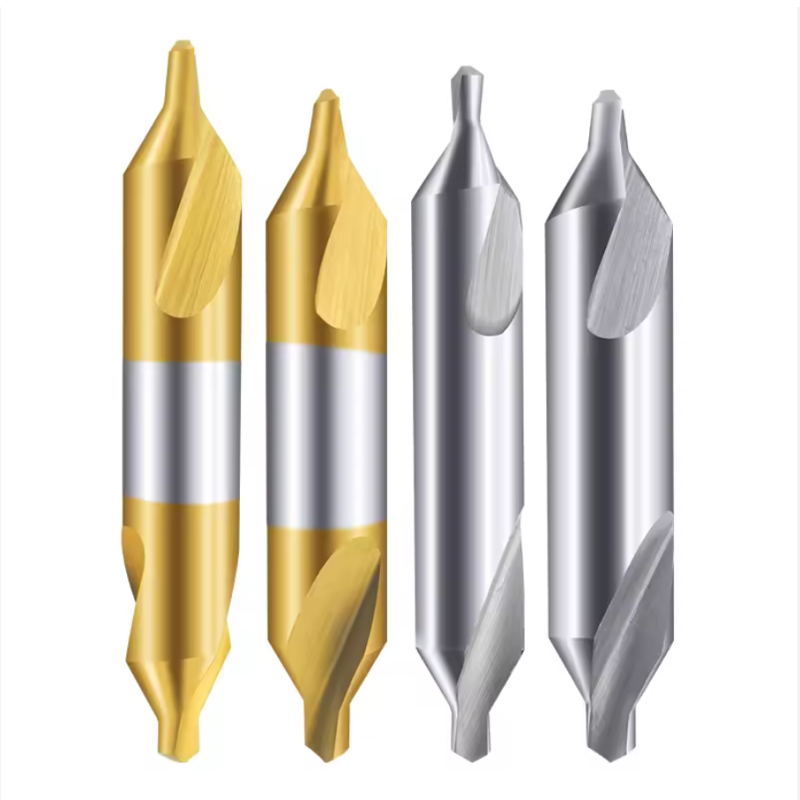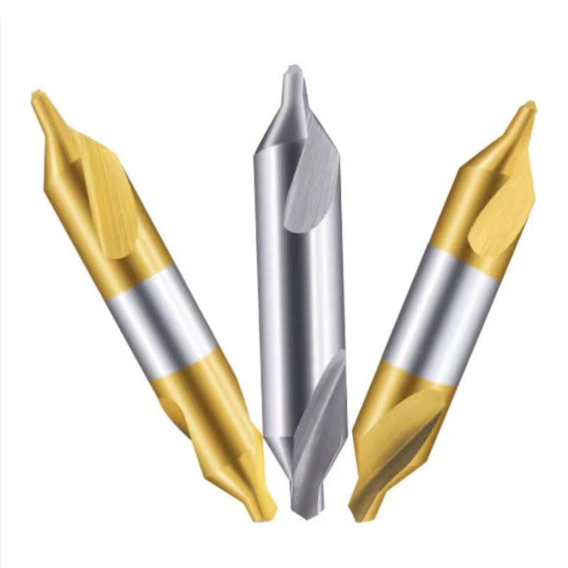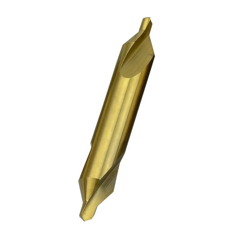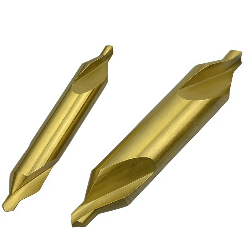


Double-Ended Coated Solid Carbide Center Drill for Aluminum, Copper and Steel
Qualità costante
Consistent geometry across repeat orders.
Ordini flessibili
Small batches and mixed sizes available.
OEM Support
Custom marking, labels and packaging.
Standard e personalizzati
Standard sizes and custom configurations.
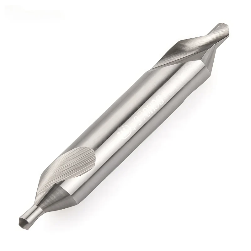
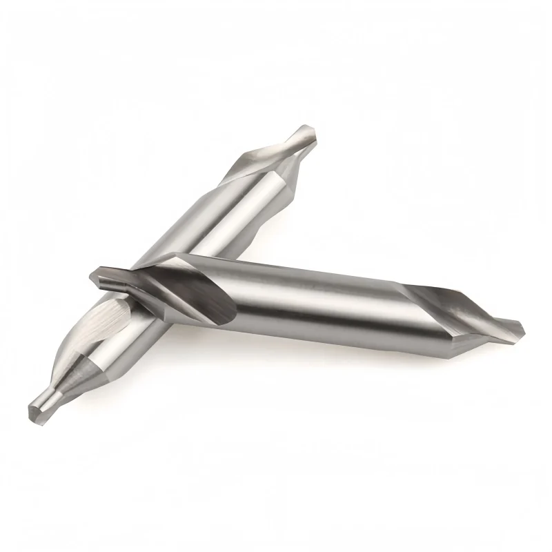
Double-Ended Coated Solid Carbide Center Drill Overview
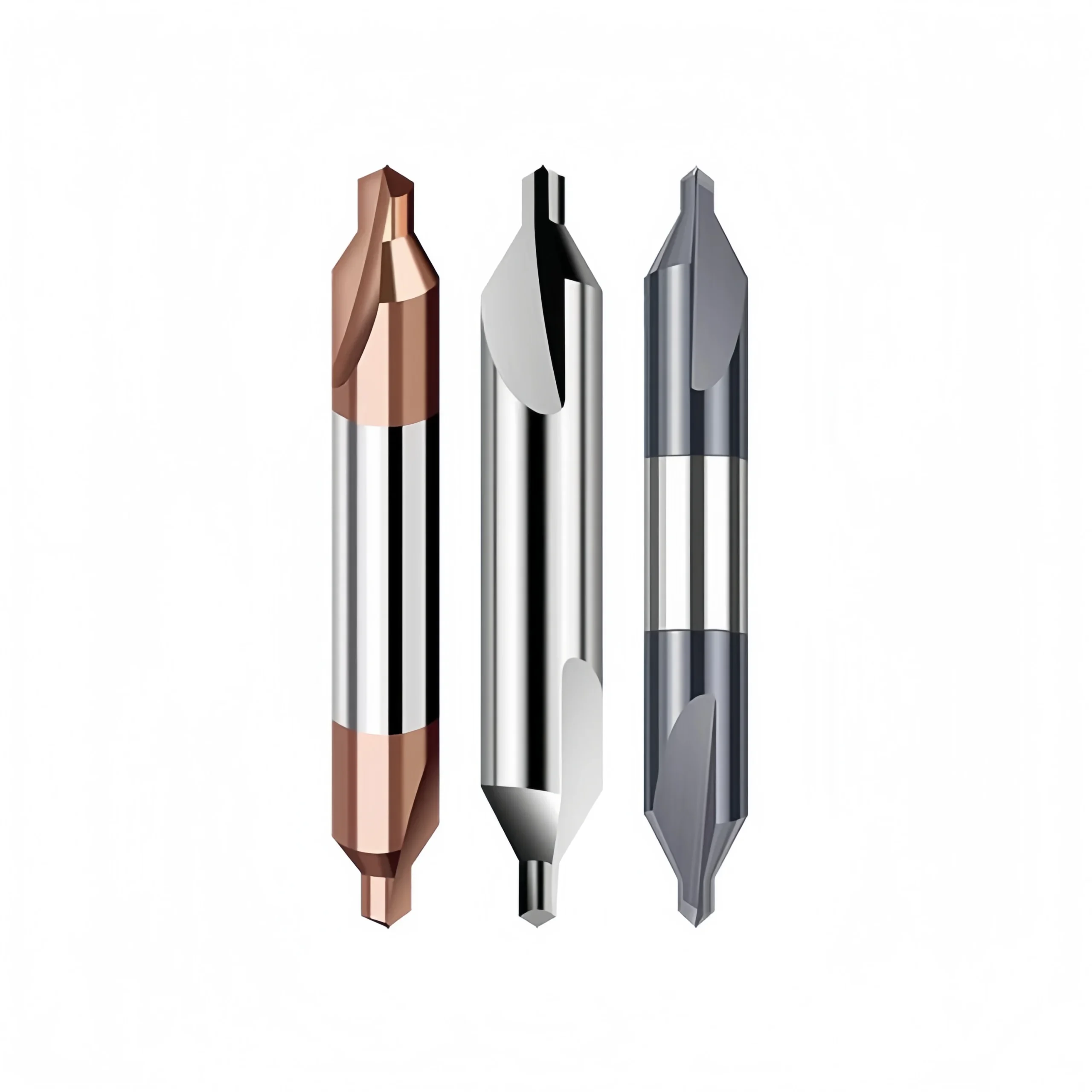
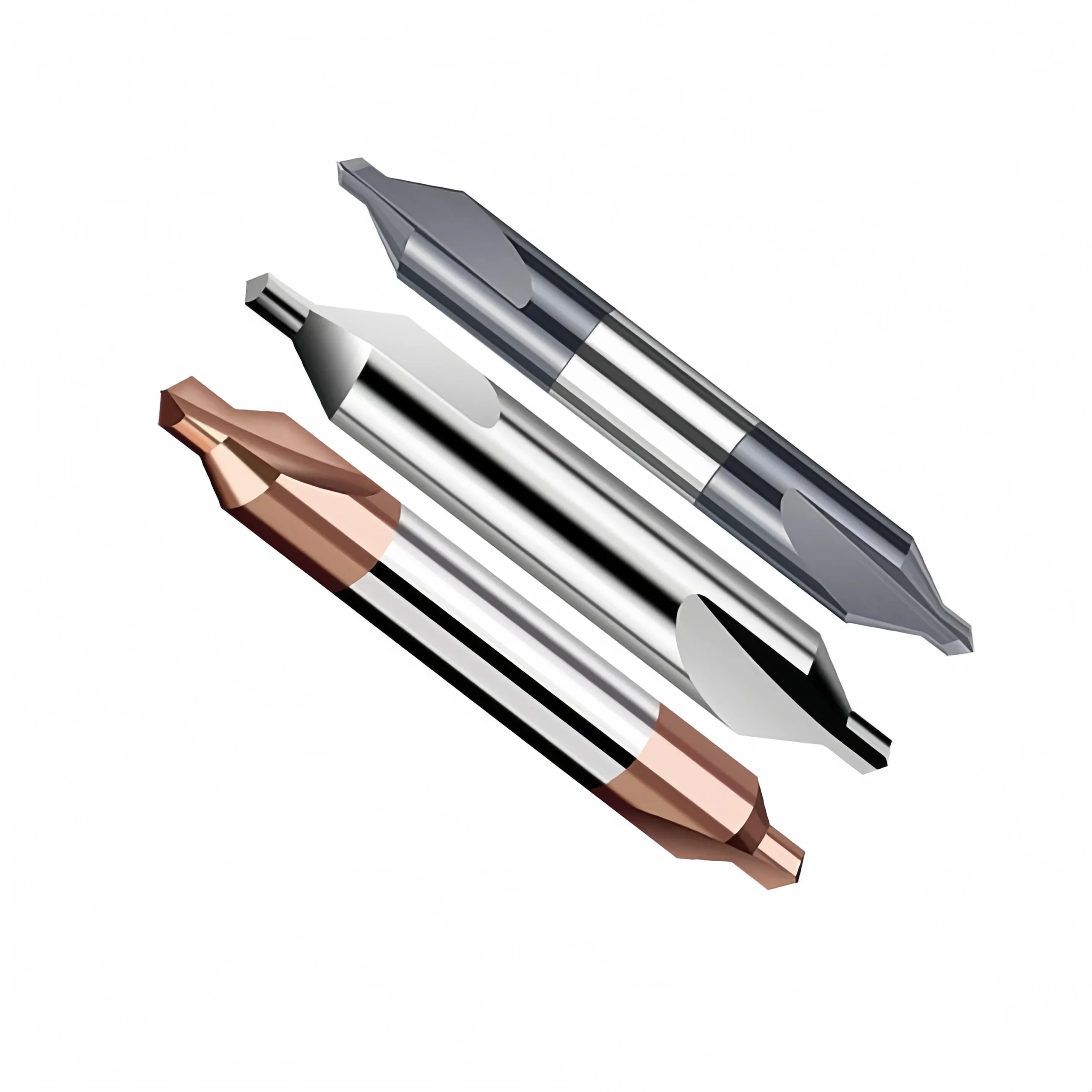
This double-ended coated solid carbide center drill is designed for accurate centering, spotting and selected light chamfering operations in aluminum, copper, steel and selected alloy-steel workpieces. Its two usable cutting ends improve tool utilization, while the short, rigid geometry supports stable positioning before follow-up drilling. Standard 90° configurations are available, with selected 60° and 120° point angles reviewed according to the required center-hole form. Diameter, length, coating, edge preparation and marking can be configured for standard purchasing or OEM requirements.
Key Configuration
Two Usable Cutting Ends
The reversible double-ended construction improves tool utilization when both cutting ends remain suitable for use.
Rigid Centering Geometry
The compact cutting geometry supports controlled tool entry and accurate starting positions before drilling.
Application-Specific Coating
Coating and edge preparation can be selected according to aluminum, copper, steel or mixed-material requirements.
Key Product Advantages


Configurable Center-Hole Geometry
Pilot diameter, body diameter, included angle and overall length can be matched to the required center-hole form or customer drawing.
Workpiece Material Compatibility
| MATERIAL GROUP | EXAMPLES | APPLICATION NOTE |
|---|---|---|
| P Steel | Carbon steel, alloy steel and tool steel | Select a wear-resistant coating |
| M Stainless Steel | Selected stainless-steel grades | Confirm edge preparation and parameters |
| N Non-Ferrous | Aluminum, copper and selected non-ferrous alloys | Use a low-friction cutting configuration |
Applications & Target Scope
- Center-hole preparation before drilling or turning
- Accurate spotting on CNC machining centers and lathes
- Selected light chamfering and countersinking operations
- Mixed-material production requiring configurable cutting geometry
- Standard, distributor and private-label OEM supply
Product & Cutting-Edge Details
Tool Nomenclature & Dimensions
Standard dimensional parameters and technical nomenclature for double-ended coated solid carbide center drills.
_副本.webp)
Standard Size Matrix
| MODEL | d1 | D | L | POINT ANGLE |
|---|---|---|---|---|
| 0.4 × D4 × 50 | 0.4 | 4 | 50 | 90° |
| 0.5 × D4 × 50 | 0.5 | 4 | 50 | 90° |
| 0.6 × D4 × 50 | 0.6 | 4 | 50 | 90° |
| 0.7 × D4 × 50 | 0.7 | 4 | 50 | 90° |
| 0.9 × D4 × 50 | 0.9 | 4 | 50 | 90° |
| 1.1 × D4 × 50 | 1.1 | 4 | 50 | 90° |
| 1.3 × D4 × 50 | 1.3 | 4 | 50 | 90° |
| 1.4 × D4 × 50 | 1.4 | 4 | 50 | 90° |
| 1.5 × D4 × 50 | 1.5 | 4 | 50 | 90° |
| 1.6 × D4 × 50 | 1.6 | 4 | 50 | 90° |
| 1.7 × D4 × 50 | 1.7 | 4 | 50 | 90° |
| 1.8 × D4 × 50 | 1.8 | 4 | 50 | 90° |
| 1.9 × D4 × 50 | 1.9 | 4 | 50 | 90° |
| 2.0 × D6 × 50 | 2.0 | 6 | 50 | 90° |
| 3.0 × D6 × 50 | 3.0 | 6 | 50 | 90° |
| 3.0 × D8 × 50 | 3.0 | 8 | 50 | 90° |
| 4.0 × D8 × 50 | 4.0 | 8 | 50 | 90° |
| 4.0 × D10 × 60 | 4.0 | 10 | 60 | 90° |
| 5.0 × D10 × 60 | 5.0 | 10 | 60 | 90° |
Recommended Starting Cutting Parameters
General starting values and detailed application parameters are available in our technical guide.
Solid Carbide Drill Cutting Data Guide
Access ISO-categorized starting speeds and feeds for application review and controlled machining trials.
Centering & Spotting Product Family
Explore related configurations for different centering, spotting and custom-hole preparation requirements.
Single-Ended Center Drills
Standard Centering
Double-Ended Series
Current Product
Solid Carbide Spot Drills
Accurate Hole Location
Custom Center Drills
Drawing-Based Geometry
For additional size ranges and related drill series, View the Solid Carbide Drill Catalog. Custom dimensions can be reviewed according to your drawing or application requirements.
Double-Ended Center Drill Customization
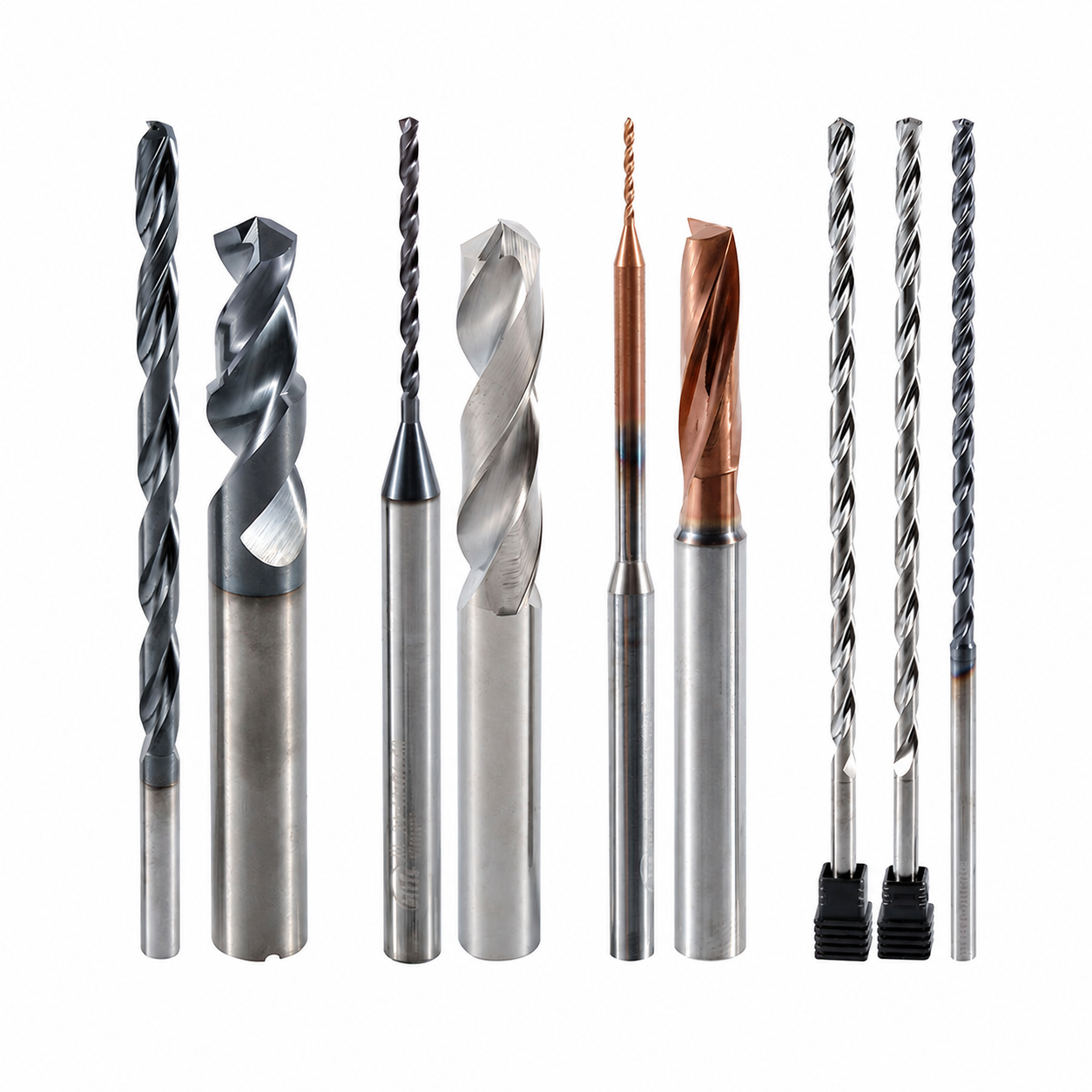
Pilot diameter, countersink diameter, point angle, cutting length, dual-end geometry, edge preparation and coating are configured according to the required centering operation, workpiece material and hole specification.
Dual-End Geometry & Edge Preparation
Both cutting ends can be configured with matching pilot sections, countersink profiles, flute geometry and edge preparation for consistent centering performance.

Dimensions & Point-Angle Options
Pilot diameter, major cutting diameter, pilot length, countersink angle, overall length and center-shank dimensions can be reviewed according to the required hole feature.
Servizi OEM e a marchio privato
OEM manufacturing and private-label supply options for industrial distributors, tooling brands and repeat-production customers.
Laser Etching
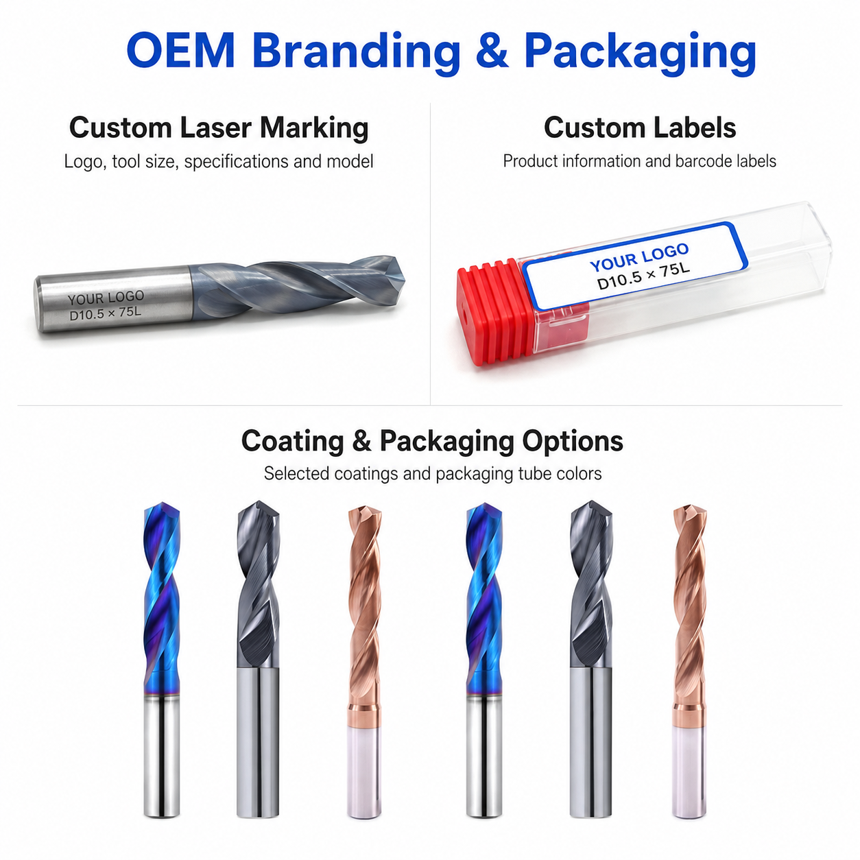
Custom marking for logos, tool codes, model numbers and dimensions can be reviewed according to the available center-shank area.
Custom Packaging
Protective individual tubes, internal supports, custom labels and private-label boxes help protect both cutting ends.
Commercial Terms
Flexible MOQ options for standard configurations, custom sizes, trial orders and scheduled repeat supply.
Technical Workflow
Inquiry
Submit the hole specification, material grade, dimensions and required quantity.
Engineering
Dual-end geometry, point angle, coating and edge preparation are reviewed.
Commercial
Quotation, MOQ, production schedule and delivery terms are confirmed.
Production
Dual-end grinding, edge preparation, coating and tool identification.
Quality Control
Both ends are inspected for diameter, angle, symmetry, concentricity and cutting-edge condition.
Inspection & Quality Control
Drill dimensions, cutting-edge geometry and visible surface condition are checked according to the confirmed product specification and application requirements.

Protective Packing for Shipment
Finished drills are protected individually before batch labeling and export-carton reinforcement.

Individual Tool Protection
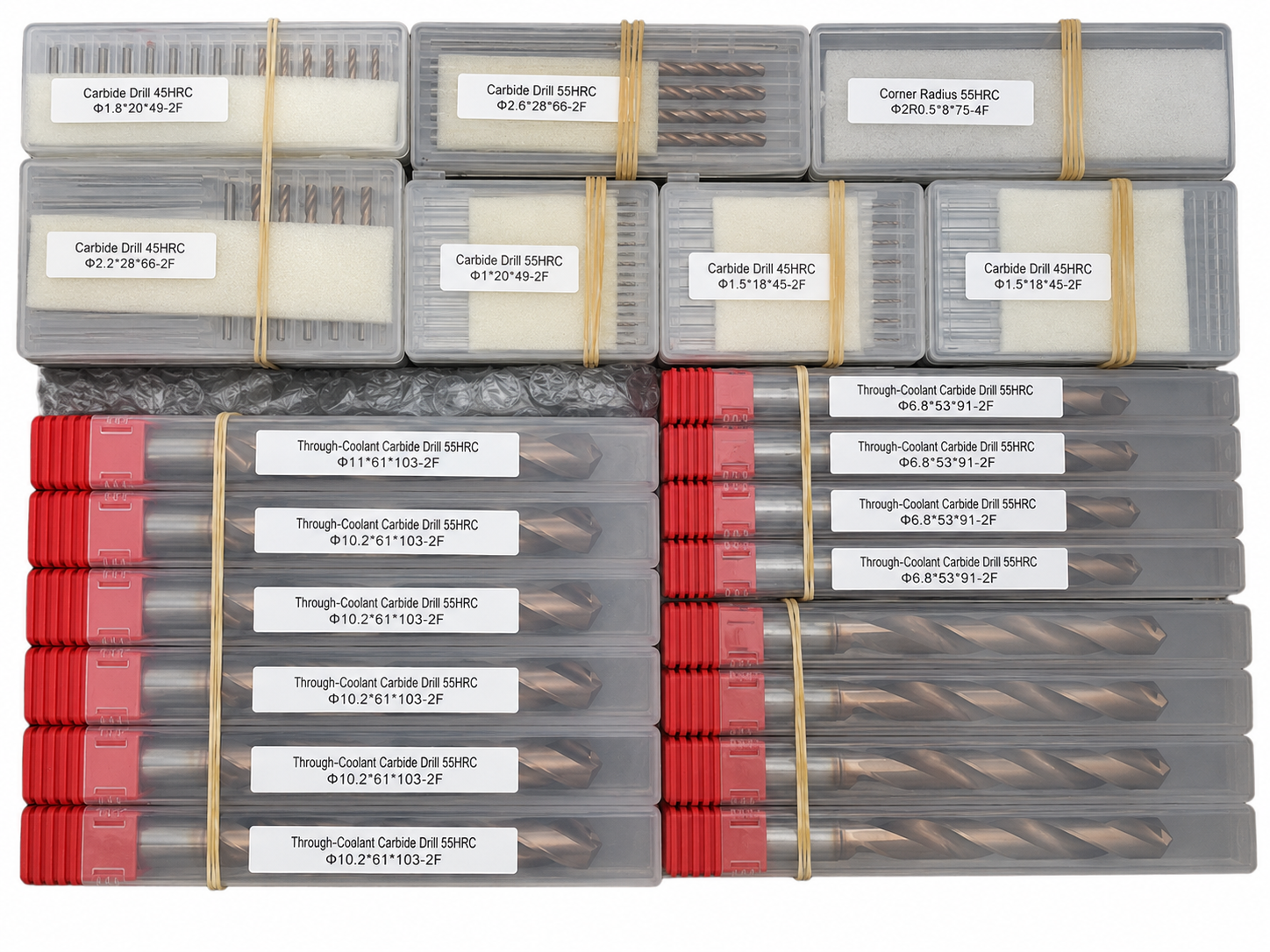
Each drill is individually protected in a plastic tube to reduce contact damage during storage, handling and transportation.
Batch & Label Verification
Tools are grouped and labeled by specification to support order verification before carton packing.

Export Carton Protection
Batch packaging, cushioning materials and reinforced export cartons are selected according to the order quantity and shipping method.
Reference Lead Time
The following timeframes are general references. Availability and production scheduling are reviewed for each order.
Shipping Options
Shipping arrangements can be selected according to order size, delivery schedule and destination.

Product FAQs
Product-specific information about applications, double-ended construction, coating selection, available configurations and machining requirements for this solid carbide center drill.
What materials is this center drill designed for?
This center drill is designed for aluminum, copper, steel and selected alloy-steel applications. The cutting geometry, coating and machining parameters should be confirmed according to the exact workpiece grade, hardness and required hole condition.
What is the advantage of the double-ended design?
The double-ended construction provides two usable cutting ends in one tool. After one end reaches its wear limit, the tool can be reversed when the second end remains undamaged, helping improve tool utilization and inventory efficiency.
What operations can this center drill perform?
It is suitable for producing center holes, preparing accurate starting locations before drilling and creating selected shallow chamfers. Final suitability depends on the pilot diameter, included angle, required center-hole form and machining setup.
How should the coating be selected for different materials?
Low-friction coating or polished cutting-edge options can be reviewed for aluminum and copper, while wear-resistant PVD coatings can be selected for steel and alloy steel. One coating may not provide the best performance across every material, so the primary workpiece should be identified before ordering.
What sizes and configurations are available?
Standard and custom configurations can be reviewed according to the product series. Pilot diameter, body diameter, cutting length, overall length, center angle and shank dimensions should be confirmed before ordering.
What information is required for a quotation?
Please provide the pilot diameter, body diameter, center angle, overall length, workpiece material, coating requirement and estimated quantity. A drawing or sample specification is recommended for custom center-hole profiles or non-standard dimensions.
Ordering & OEM FAQs
General information for trial orders, mixed-size purchasing, private labeling and production scheduling.
Do you accept small trial orders?
Yes. Small sample or trial orders are welcomed for dimensional verification and machining evaluation before committing to volume purchasing.
Can mixed sizes and coating options be ordered together?
Yes. Different standard or custom sizes can be combined in one order when the production and coating requirements are compatible. Mixed-size ordering is suitable for distributors, resellers and batch inventory planning.
Is OEM laser marking available?
Yes. Custom laser marking such as a logo, model number, size or batch identification can be reviewed together with OEM labels, individual packaging and outer-box requirements.
What is the typical production lead time?
Standard stock items normally have a shorter lead time, while custom dimensions, special coatings and OEM packaging require additional production time. The exact schedule is confirmed according to specification, quantity, coating and current production capacity.
Downloads & Technical Resources
Access product dimensions, series information and starting cutting data for product selection and application review.
Need Sizes, Pricing or Custom Options?
Send us the required tool type, sizes, quantities, workpiece material and any OEM or custom requirements. We will confirm suitable specifications, availability, lead time and quotation details.
Drawings, size lists and reference photos are welcome.