
Cómo elegir brocas y fresas para PCB: guía de selección
Choosing PCB drills and router bits starts with the operation, board construction and quality target—not diameter alone.
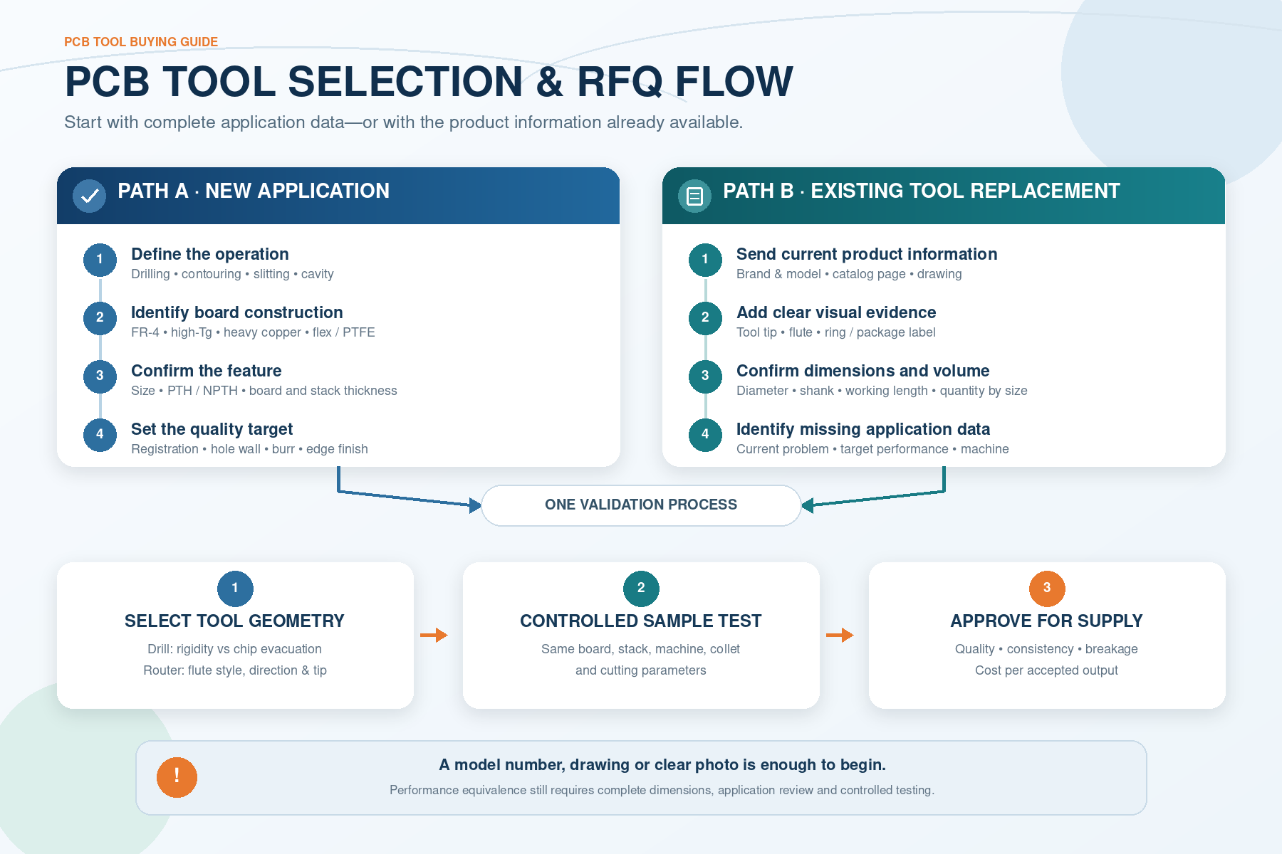
This guide helps production teams select a tool and helps buyers, sourcing teams and tooling suppliers compare existing models, prepare a useful RFQ and evaluate samples before a bulk order.
PCB Drills and Router Bits: Quick Selection Table
Use this table to identify the tool family. Final geometry and cutting data must still be checked against the actual board, stack and machine.
| Operation | Typical tool | Main information to confirm |
|---|---|---|
| Through-hole drilling | Solid carbide PCB drill | Production drill size, PTH/NPTH, stack and hole-quality target |
| Mechanically drilled micro-hole | Micro PCB drill | Diameter, aspect/stack demand, runout and registration accuracy |
| Board contouring | Diamond-cut/cross-cut or chip-breaker router | Board material, edge quality, routing distance and extraction |
| Slitting or narrow slot | Two-flute router or suitable PCB slot tool | Slot width, cutting depth, burr and dimensional tolerance |
| Pocket or cavity | End-cutting or drill-point router | Entry method, bottom finish, wall finish and depth |
| Flex, PTFE or soft material | Sharp router with sufficient chip space | Support, heat, swarf evacuation and edge quality |
| Long routing distance or abrasive board | Wear-resistant geometry; coating if justified | Wear mechanism, dimensional stability and cost per routed metre |
Swipe horizontally to view the full table.
1. PCB Drills vs Router Bits: Define the Operation First
PCB drills produce round holes such as component holes, through holes and mechanically drilled micro-holes. PCB routers remove material laterally for profiling, depaneling, slitting, slots, pockets, cavities and selected edge features.
A matching diameter does not make the tools interchangeable. A drill is designed mainly for axial entry and hole quality. A router must resist radial load, evacuate swarf during lateral movement and control the routed edge. Even among routers, a contour tool may not be suitable for plunging or pocket-bottom finishing.
2. Start with the Information You Already Have
PCB manufacturers and process engineers may know the laminate, stack and machine parameters. A buyer or tooling supplier may only have a current model code, purchasing list, catalog page or sample. Both are valid starting points.
- Complete application data: provide the board material, operation, dimensions, stack, machine and quality target.
- Existing-product replacement: provide the current brand and model, drawing, specification sheet or readable packaging label.
- Limited information: provide clear photos of the tool, tip, flute and ring/label plus the quantities used by size.
If you are sourcing tools for an end customer, incomplete board or machine data does not prevent an initial review. It should instead be listed as information to confirm before sample approval.
We can first compare the available dimensional and geometric features, then identify the application data still needed for a suitable sample proposal. However, visual similarity alone cannot prove equivalent performance. Carbide grade, edge preparation, tolerances and inspection criteria also matter.
3. Choose PCB Drill Size, Length and Hole Type
For a plated through hole (PTH), the required finished diameter is generally not the production drill diameter. Hole-wall plating reduces the opening, so drill compensation must follow the PCB manufacturer’s process allowance. A non-plated through hole (NPTH) does not use the same plating compensation, although machining and inspection tolerances still apply.
Use this sequence:
Finished hole requirement → PTH or NPTH → production drill diameter → board and stack thickness → drill geometry → process verification.
Also confirm cutting diameter, shank diameter, flute or working length and overall length. Extra flute length is not a free safety margin. More unsupported length reduces rigidity and can worsen deflection, registration and breakage risk. Select only the length needed for the complete stack and entry/backup arrangement.
As diameter decreases, spindle runout and collet condition become increasingly significant relative to tool size. UNION TOOL’s troubleshooting guidance recommends controlling runout below 10 µm and notes that below 5 µm is preferable for drills under 0.3 mm; treat this as manufacturer guidance, not a universal acceptance limit for every line.
4. Choose PCB Drills by Performance Priority
Two drills with the same nominal size may use different web, flute, taper, margin and point designs. UNION TOOL groups PCB drill designs around three broad priorities:
| Priority | Geometry emphasis | What to verify |
|---|---|---|
| Hole registration | Rigidity and reduced deflection | Runout, entry stability, stack height and tool length |
| Hole-wall quality | Chip space and evacuation | Flute capacity, chipload, vacuum, copper structure and smear |
| Balanced performance | Compromise between rigidity and evacuation | Which defect sets the real production limit |
Swipe horizontally to view the full table.
The difference is not merely theoretical. KYOCERA’s PCB drill range includes separate designs for hole-wall quality, accuracy, reduced deflection, flex circuits and blind-via applications. Therefore, do not approve an alternative from diameter and length alone.
5. Match PCB Drills and Router Bits to the Board Material
“PCB material” is not one machinability group. Standard FR-4, high-Tg laminates, high-layer-count or heavy-copper boards, halogen-free materials, flex circuits, PTFE-based laminates, package substrates and metal-backed boards create different wear, heat and swarf conditions.
| Board construction | Main concerns | Selection direction |
|---|---|---|
| Standard FR-4 | Glass-fibre wear, registration, hole/edge quality | Start with a proven general geometry, then optimize for the quality limit |
| High-Tg or halogen-free laminate | Heat and wear may differ from standard FR-4 | Use material-specific tool and parameter recommendations |
| High-layer-count or heavy copper | Cutting load, heat, spiral copper chips and evacuation | Review stack height, chipload, hit count and flute capacity together |
| Flex or PTFE-based material | Tearing, debris deposition, heat and support | Use sharp, low-load geometry with adequate chip space and board support |
| Metal-backed or non-ferrous board | Adhesion, burr, wear and cutting load | Consider dedicated sharp geometry and a validated low-friction coating |
Swipe horizontally to view the full table.
6. Choose PCB Router Bit Geometry by Operation
Router names are not fully standardized across suppliers, so compare geometry and application rather than relying on one marketing term.
| Router geometry | Typical strength | Confirm before ordering |
|---|---|---|
| Diamond-cut / cross-cut | General contour routing with many small cutting segments | Edge finish, swarf extraction, routing distance and board type |
| Chip-breaker | Breaks swarf into smaller pieces and can reduce radial load | Stack height, feed capability, edge quality and breakage margin |
| Two-flute | Defined cutting edges and larger chip passages | Slitting, soft material, non-ferrous board or cavity requirement |
| Single-flute / large chip pocket | Chip space and lower heat risk in selected soft materials | Material support, edge finish, feed and extraction |
| Up-draft | Moves swarf upward toward effective vacuum extraction | Pressure-foot, vacuum and surface-burr requirement |
| Down-draft | Selected designs can reduce top-surface burr or suit manual routing | Board support, fixing, swarf path and dimensional target |
| Fish-tail tip | Common contour-routing end form | Whether entry begins from a pre-hole or open edge |
| Drill-point / end-cutting tip | Supports direct entry or cavity work in a tool designed for it | Exact plunging capability and bottom-finish requirement |
Swipe horizontally to view the full table.
UNION TOOL’s router line separates contour, slitting, cavity, soft-material, non-ferrous and coated designs. Topoint’s router range also distinguishes fish-tail, drill-point and end-mill-style tips.
See our PCB router bit range; send drill or slot specifications for review.
Uncoated carbide is suitable for many standard applications. A coating may be justified by abrasion, adhesion, routing distance or dimensional-stability requirements, but it should not be selected from colour alone. Coating also cannot correct poor runout, excessive flute length or inadequate swarf extraction.
7. Check Spindle, Stack and Cutting Conditions
Tool selection and process conditions must be evaluated together. Confirm spindle-speed range, feed or chipload, collet condition, dynamic runout, stack height, entry and backup material, pressure-foot condition, board fixing, vacuum performance and the planned tool-life limit.
Higher stack height can increase chip volume, load and deflection. Excessive flute length can reduce routing accuracy. Inadequate vacuum can cause swarf clogging, while an unsuitable speed/feed balance can accelerate wear even when the tool does not break.
Use data for the exact tool diameter, board construction and machine. UNION TOOL’s PCB technical resources publish separate drilling, routing and troubleshooting information rather than one universal parameter set.
8. Evaluate PCB Tool Samples Before Bulk Purchase
A low sample price or high hit count does not prove that two products are equivalent. Test the old and new tool on the same board construction, stack, machine, collet condition, entry/backup material and cutting parameters.
| Drill sample checks | Router sample checks | Commercial check |
|---|---|---|
| Registration and diameter | Routed dimension and tool deflection | Consistency between pieces and batches |
| Hole-wall roughness and smear | Edge/surface roughness and burr | Usable life before quality limit |
| Nail heading, wicking and burr | Swarf evacuation and diameter reduction | Breakage rate and cost per accepted output |
| Bird nesting and drill wear | Routed distance before deterioration | Packaging, label and traceability |
Swipe horizontally to view the full table.
These criteria align with UNION TOOL’s standard PCB tool evaluation. Define the acceptance limit before testing. A tool that survives longer but produces unacceptable holes or routed edges has already reached the end of its useful life.
9. How to Prepare a PCB Drill or Router RFQ
Standard-size replenishment
Provide tool type, cutting diameter, shank diameter, working/flute length, overall length, geometry or tip style, quantity per size and any packaging or label requirement.
Replacement of an existing series
Provide the current brand and model, catalog page, drawing or readable photos. Add the current problem, target performance, trial quantity and expected monthly or annual demand when known.
New or custom requirement
Provide the board material and construction, operation, finished feature, PTH/NPTH where relevant, board and stack thickness, quality target, machine capability, trial quantity and expected production volume.
10. Practical PCB Drill Replacement Example
A tooling supplier receives an end customer’s purchasing list showing a Ø0.25 mm PCB drill and the required quantity, but no board or machine data. This is enough to begin a review, but not enough to claim performance equivalence.
- Verify the specification: confirm that Ø0.25 mm is the production drill diameter—not only the finished PTH requirement—and check the shank, working length and overall length from the current catalog, label or drawing.
- Confirm the missing application data: ask for the board construction, PTH/NPTH, board and stack thickness, machine condition and whether registration or hole-wall quality is the main limit.
- Select a trial candidate: match the dimensions first, then choose a rigidity-, evacuation- or balance-oriented geometry according to the confirmed priority.
- Approve from controlled results: test the candidate beside the current drill under the same setup and compare registration, wall quality, burr or smear, wear consistency, breakage and cost per accepted hole.
The important lesson is that a model list can start an enquiry, while controlled application data is what turns a dimensional match into a reliable, application-based replacement decision.
11. Use Machining Problems as Selection Evidence
A problem does not automatically prove that the tool is wrong. Record when it appears and check the tool, setup and process together.
| Problem | Tool evidence | Process evidence |
|---|---|---|
| Poor hole registration | Rigidity, wear and working length | Runout, entry, stack preparation and feed |
| Rough hole wall or smear | Flute space, margin and wear | Chipload, heat, stack and vacuum |
| Router burr or rough edge | Sharpness, wear and flute direction | Feed, speed, routing direction and fixing |
| Dimensional error | Router rigidity and diameter reduction | Runout, stack height, board movement and tool offset |
| Swarf clogging or breakage | Chip space, flute length and tip form | Extraction, entry method, feed/speed balance and collet condition |
Swipe horizontally to view the full table.
12. PCB Drills and Router Bits: Final Selection Checklist
- Define drilling, contouring, slitting, pocketing or another operation.
- Confirm board material, copper/layer structure and stack height.
- Separate finished PTH size from production drill size.
- Confirm cutting diameter, shank, working length and overall length.
- Choose the drill by registration, hole wall or balanced priority.
- Choose the router by geometry, flute direction, tip and entry method.
- Check runout, collet, fixing, vacuum and machine capability.
- Use coating only when the wear mechanism and economics justify it.
- Compare samples under controlled conditions and quality limits.
- Provide quantity by size plus packaging or labeling requirements.
A practical sourcing sequence is: available model/application data → dimensional match → geometry and board review → sample plan → controlled quality test → total-cost comparison → bulk approval.
Preguntas frecuentes
Can I request a PCB tool quotation with only a model number?
Yes. A current model number, catalog page, drawing or readable tool and package photos can start the comparison. Application data is still needed before claiming full performance equivalence.
Is the finished PTH diameter the same as the drill diameter?
Usually not. Hole-wall plating reduces the opening, so the production drill size is generally larger. Use the PCB manufacturer’s process allowance rather than a universal compensation value.
Are diamond-cut and diamond-coated router bits the same?
No. Diamond-cut or cross-cut identifies a router tooth geometry. Diamond-coated identifies a coating applied for wear resistance. A tool may have diamond-cut geometry without a diamond coating.
Is an up-draft PCB router always better?
No. Up-draft designs can work well with effective vacuum extraction. Selected down-draft designs may better suit a top-surface burr or manual-routing requirement. Evaluate the full geometry and setup.
How should a buyer compare two PCB tool suppliers?
Compare dimensions and geometry first, then test both tools on the same board, stack, machine and parameters. Judge accepted hole or edge quality, consistency, breakage and cost per accepted output—not unit price or maximum life alone.